HOLIDAY DONATION DRIVE - SUPPORT MSW - DO YOUR PART TO KEEP THIS GREAT FORUM GOING! (Only 13 donations so far - C'mon guys!)
×


JSGerson
-
Posts
2,611 -
Joined
-
Last visited
Content Type
Profiles
Forums
Gallery
Events
Everything posted by JSGerson
-
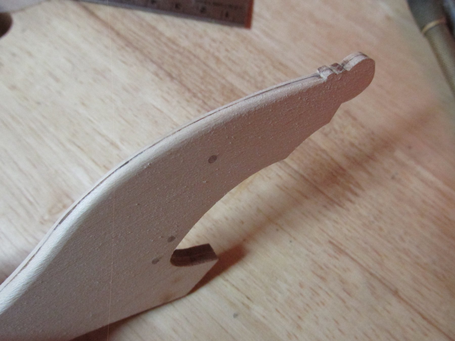
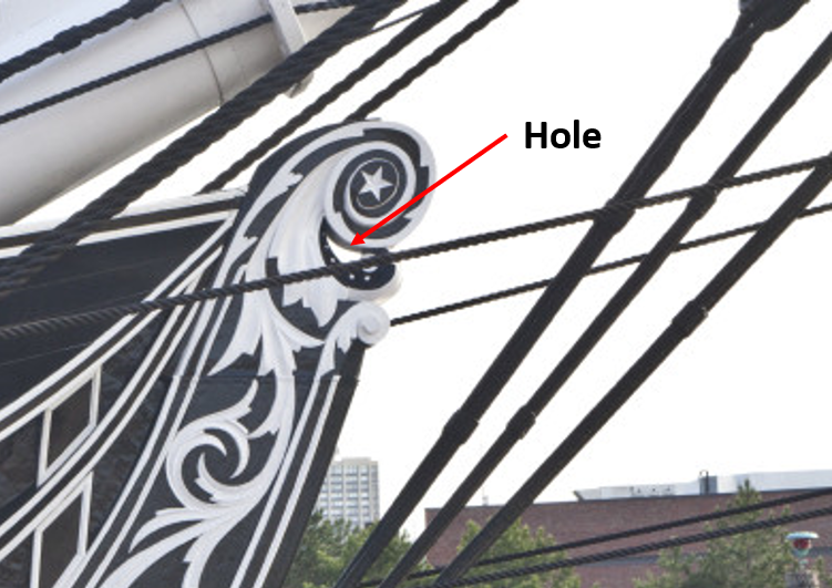
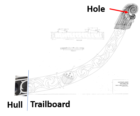
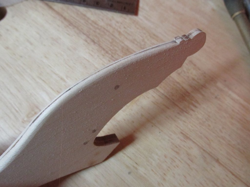
 Trailboard Preliminaries Looking at the stem piece, it seemed to me that now would be a good time to think about the trailboard decorations. Because I have the US Navy plans CD from the USS Constitution Museum, I have the plans for the decorations and the billet head so why not use that instead of the kit’s rendering? The billet head is a separate drawing. I merged the two images on the computer and printed a kit size template. The reason I did this, is because the billet head has a carved hole which does not appear in the kit plans, but is obvious when looking at the real ship. I laid the template on the stem and marked the shape and position of the opening with pin marks. One other thing I have not seen in other builds. The trailboard decorations are not completely on the trailboard. Just a bit wraps onto the hull. Strangely, the CD does not have that part of the decoration plan, so I used an image of the real ship to complete the design on my template. But before I can move forward anymore, I have to make preparations for my Thanksgiving trip to colonial Connecticut. It’s going to be a big shebang at my Sister’s house with relatives coming as far away as Tokyo, Japan, Seattle, WA and myself from South Carolina.
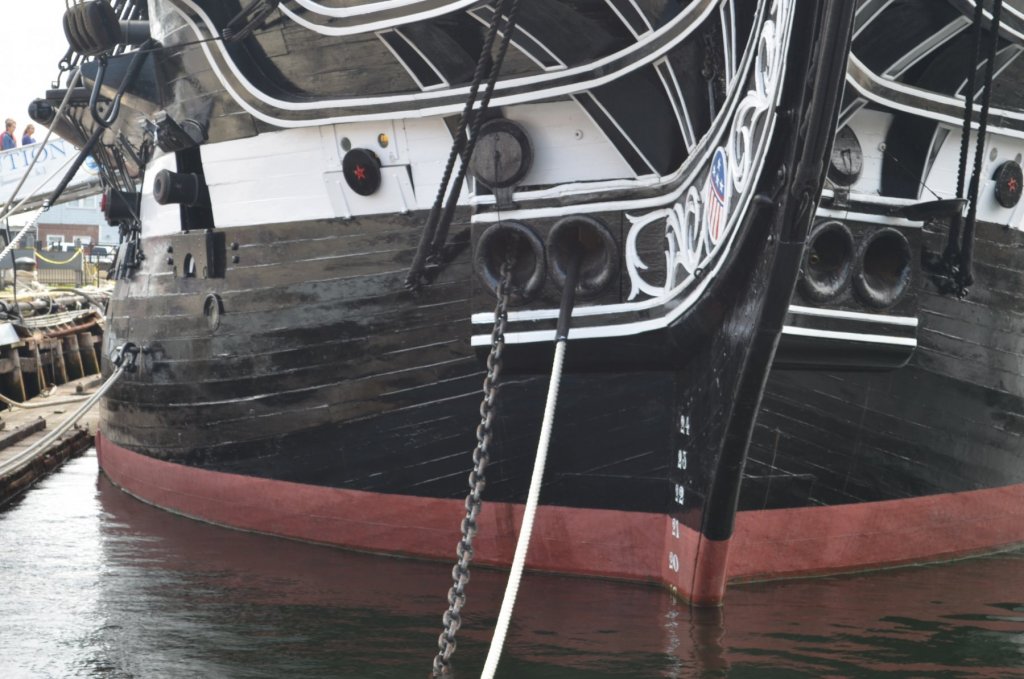
-
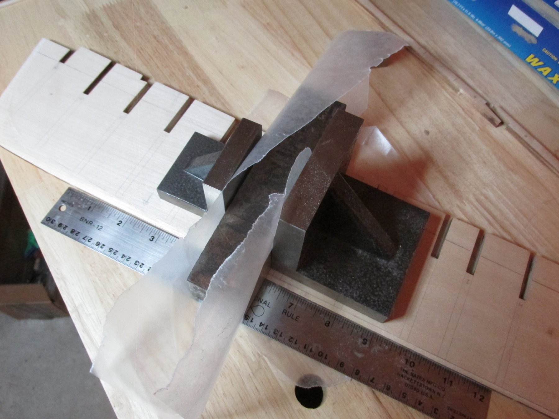
Wow, it’s been about a month since my last post. I’ve been a bit busy, but not so much directly with the model. I went to St. Petersburg, Florida for the 2017 NRG Conference which is always worth the trip. Then since I was already in Florida, I visited my Mom for a week. Once I got back home I had about two weeks of mail, bills, etc. to work my way through, and other sundry things. Oh, and while I was away, my toilet leaked, so I had to get that taken care of. Finally, I got my head back in builder mode. Right now, I’m thinking of replacing sections of the keel with the authentic oak from the ship and then inserting flush vertical tubes through the oak section of the keel. The oak would be nice and strong, and the tubes would hold thick pins sticking up from the pillars mounted on a board. This would allow me to remove the model from the display as needed and would, should I decide to, allow me to use a cradle interchangeable. So far, I have created the rabbet on keel bulkhead and tapered the stem and rudder post pieces as indicated in the plans. The three pieces of the keel bulkhead have been glued together and the two joints reinforced with 1” x 2” 1/32” plywood. I used wax paper so that my weights would not be glued to the wood. The glue did adhere slightly to the wax on the paper which gave the wood a water stained look.


-
Ouch! I know know your stomach twisted as you watched the model fall in what seemed like slow motion. But, you sucked it up, and performed a nice clean repair, which if you keep quiet about it, no one will ever know. Nice job.
- 152 replies
-
- 1
-

-
- rattlesnake
- Model Shipways
- (and 1 more)
-
I keep promising myself that I'll buy a mini Lathe (probably a Sherline) but other expenses keep getting in the way, not to mention I have to learn the skills too. I still have time as I won't be needing one for a good while at the rate that I build. I suppose I could have made those sheaves with a Dremel and a file. I got pretty good making cleats that way. Jon
- 742 replies
-
- 6
-
-
- constitution
- frigate
- (and 1 more)
-
The brass sheaves, how did you make them? It looks like there might be a rope groove on them. Also, I'm curious if you used any pins where the rails meet at right angles with each other, for structural joint strength. I can see the pins for anchoring them to the deck. Jon
- 742 replies
-
- 5
-
-
- constitution
- frigate
- (and 1 more)
-
I just got back from Florida having attended the NRG Convention in St. Petersburg and then a week long visit with Mom on the other side of the state in Southern Florida, so I'm just catching up. That was a nice job with the gun ports. My only fear is that they have a tendency to get knocked off while manipulating the model during the build process. At least I had that problem with my Rattlesnake build. I like the cut out as well. I did the same type of thing with the "Ratlter." So take care and handle her gingerly from now on. She looks great.
- 742 replies
-
- 6
-
-
- constitution
- frigate
- (and 1 more)
-
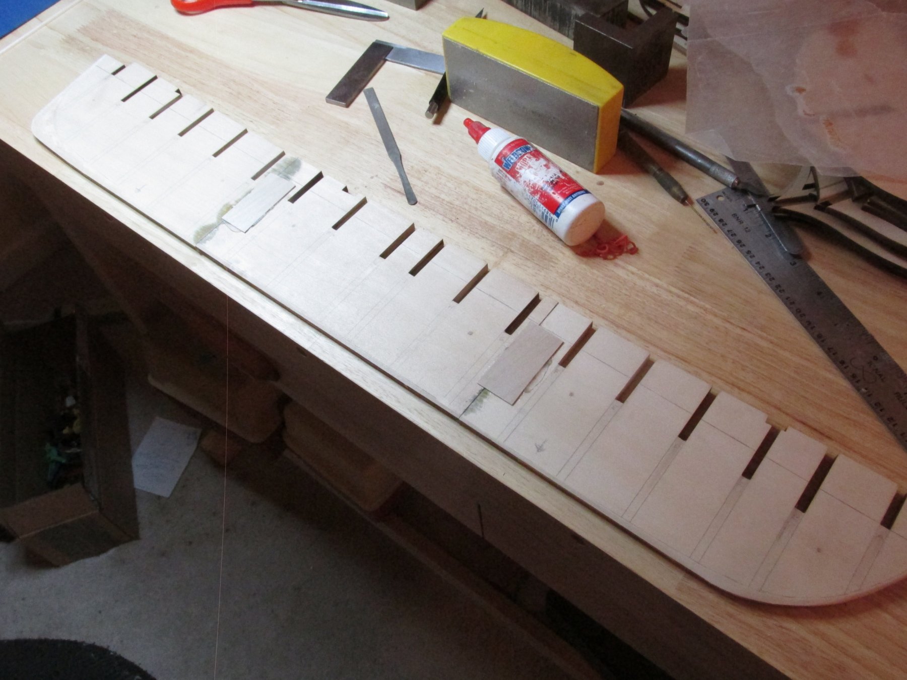
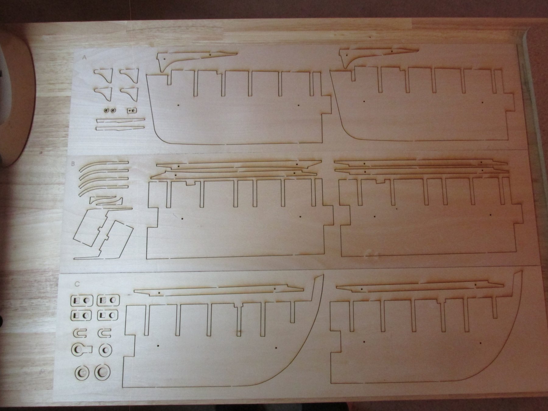
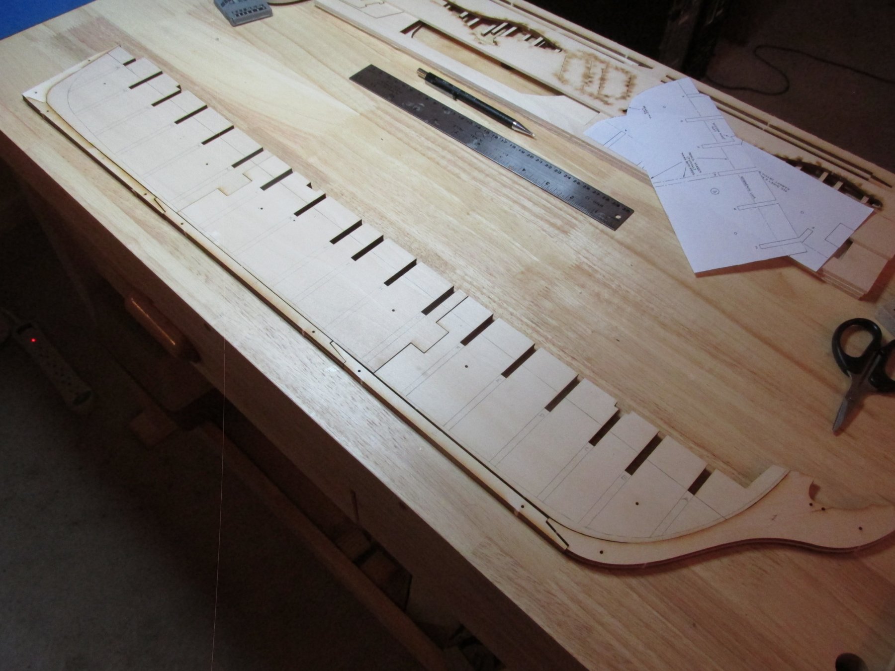
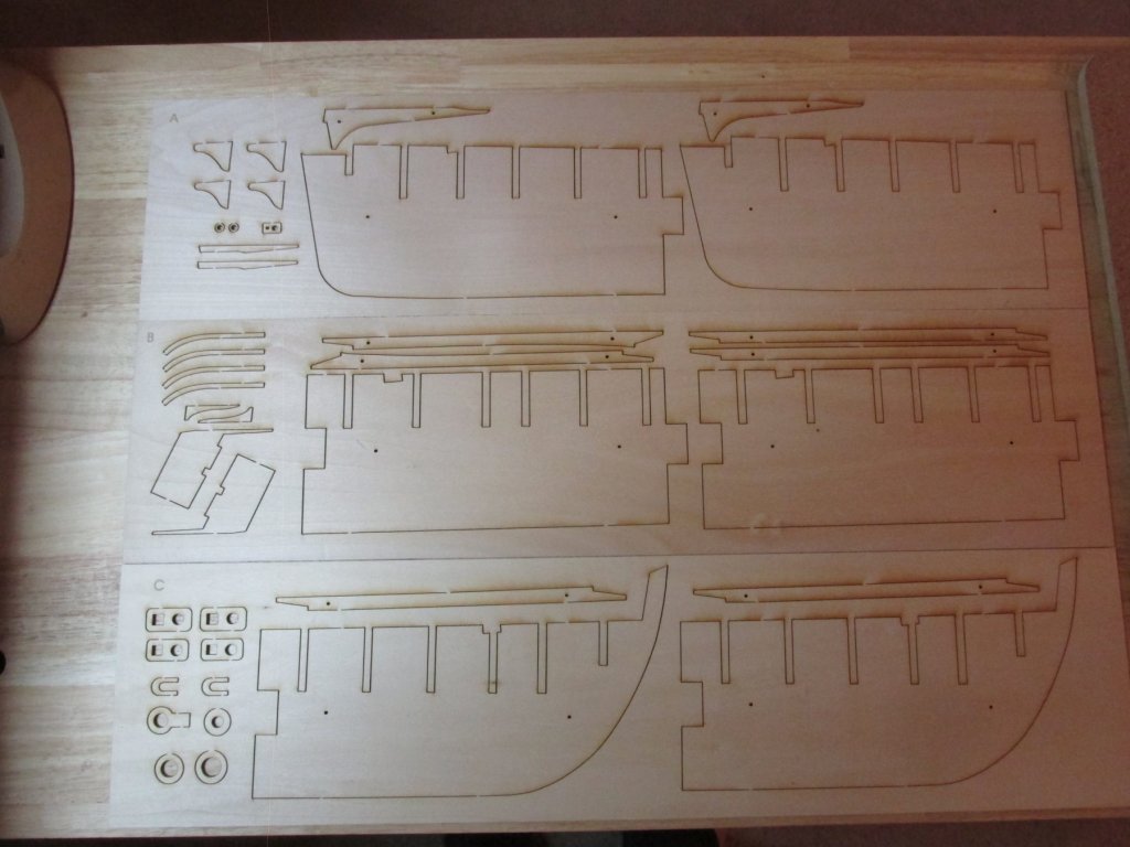
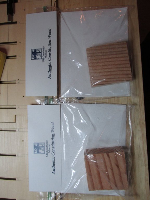
The Main Build So much for the appetizers, now the main course! With a deep breath, I took the sheets with the keel parts from the box. I carefully removed them from the sheets and marked them with their respective reference lines. Nothing has been trimmed or glued, just laid out on the table. Some major decisions need to be made now. First – Am I going to use the simulated guns or opt for showing some of the lower deck which would require buying additional guns and carriages? Second – How is the model to be displayed, with pedestals or a cradle? If with pedestals, I want to ensure that the pedestal screws won’t break the keel should the model get moved or handled a bit rough. I want to re-enforce those areas. If a cradle is used, how is the model held down during transport, should it need to be moved. This is a problem I presently have with my Rattlesnake. Third – I have a couple of pieces of authentic USS Constitution oak wood which I would like to incorporate into the model. The pieces are approximately 2 ¼” x 2 3/8” x 7/8 – 5/8” and 2 3/8” x 2 3/8” x ¾”. They were purchased just before the ship went into dry dock 3 years ago. I have not been able to procure any additional wood since, let alone different sizes or shapes. I would welcome any and all suggestions especially on how to use the oak wood pieces.

-
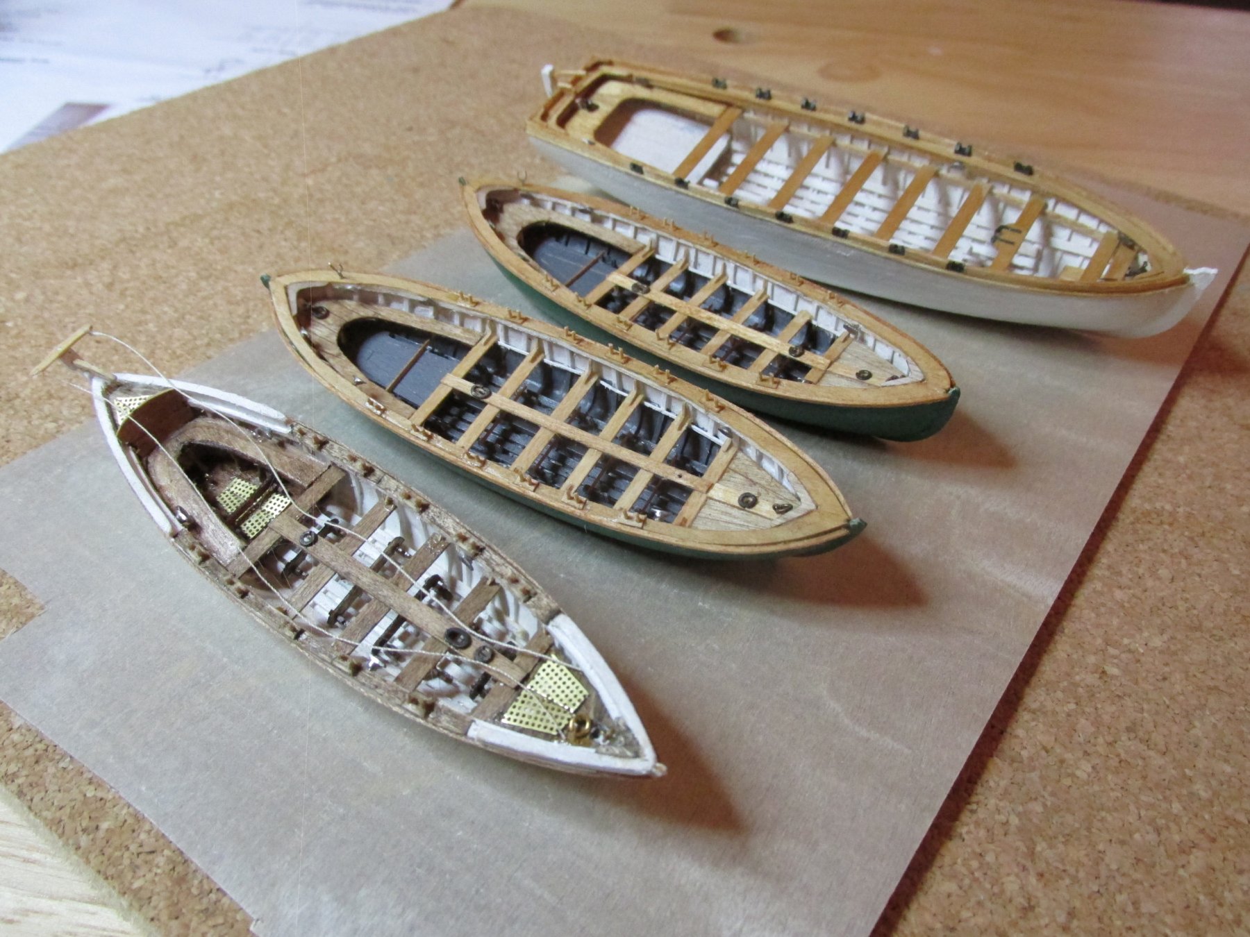
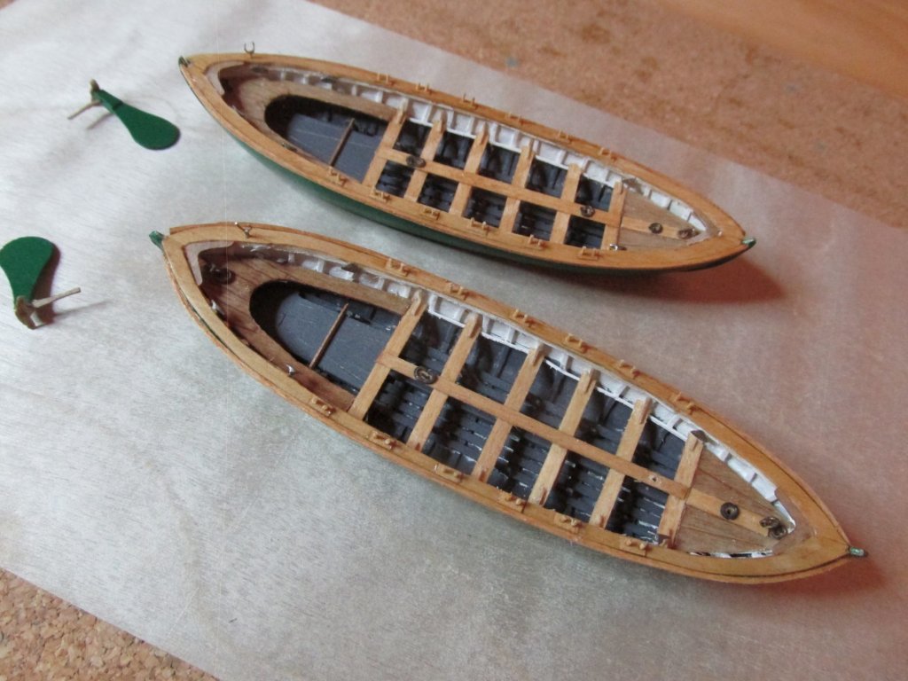
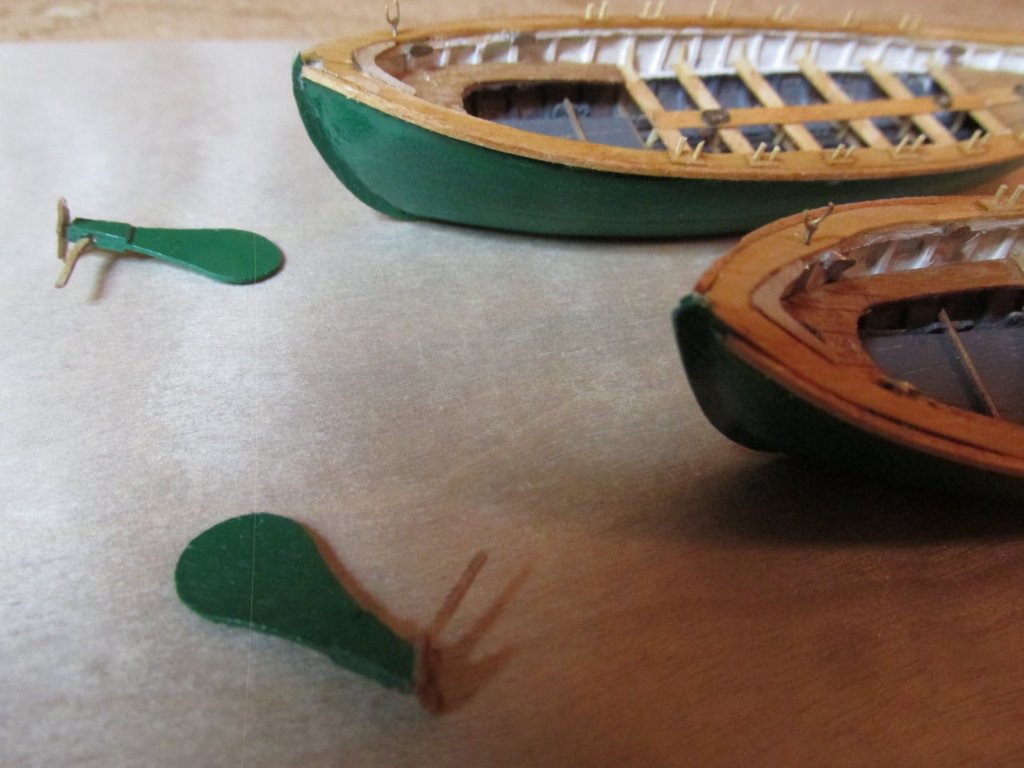
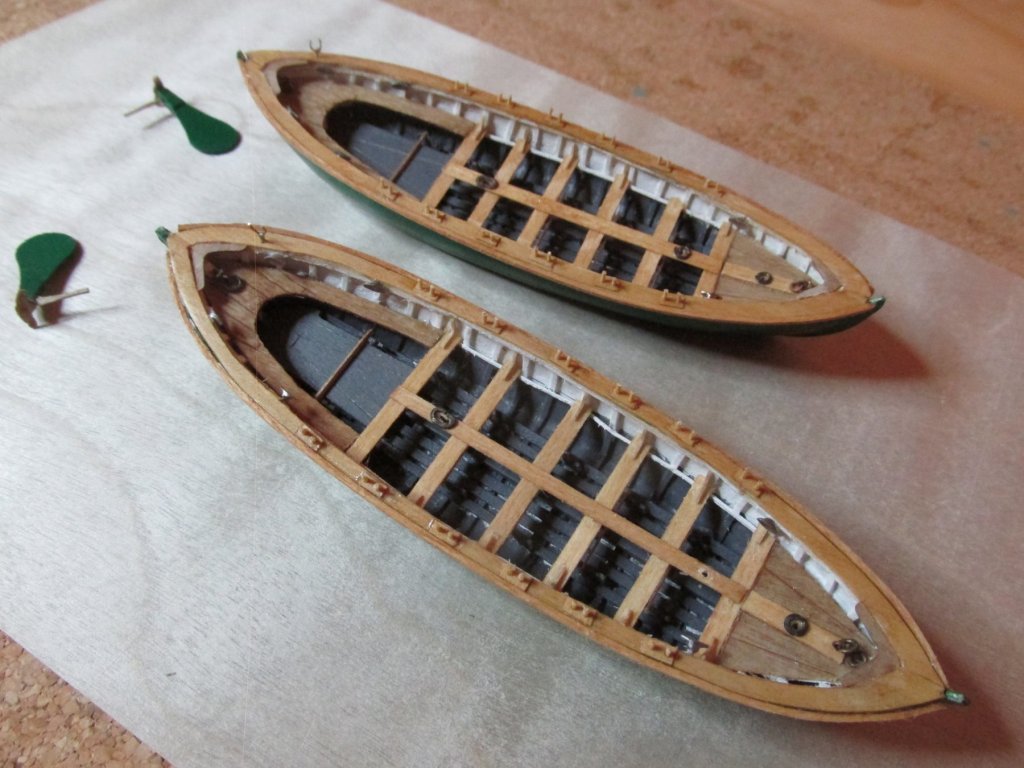
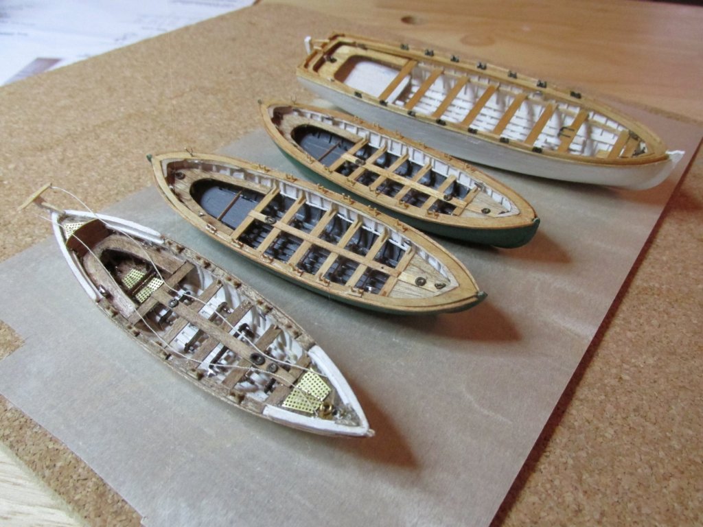
Final Touches I chose not to attach the rudder assembly to the boats due to their very delicate structure. In actuary, the rudders are not stored inside boat when not used. All the oars, masts, and any other accoutrements will be made at the time the boats are to be installed.

-
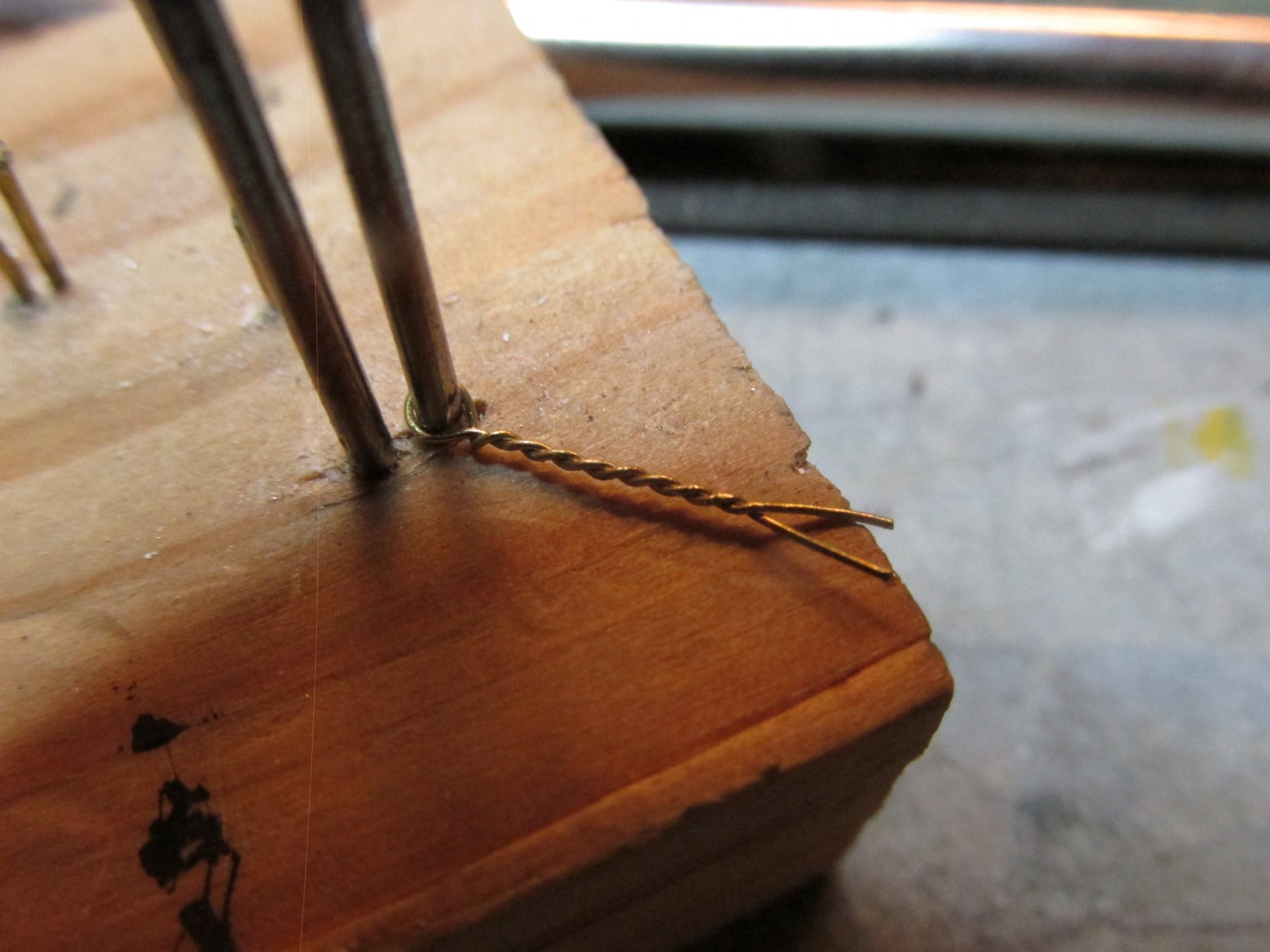
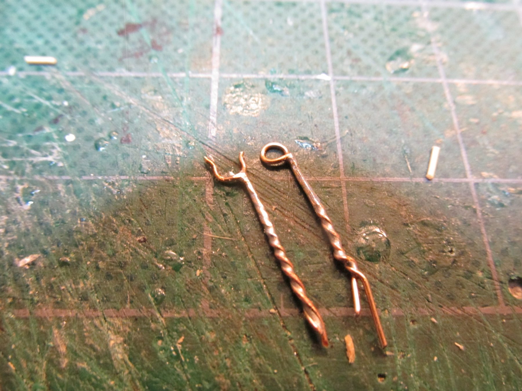
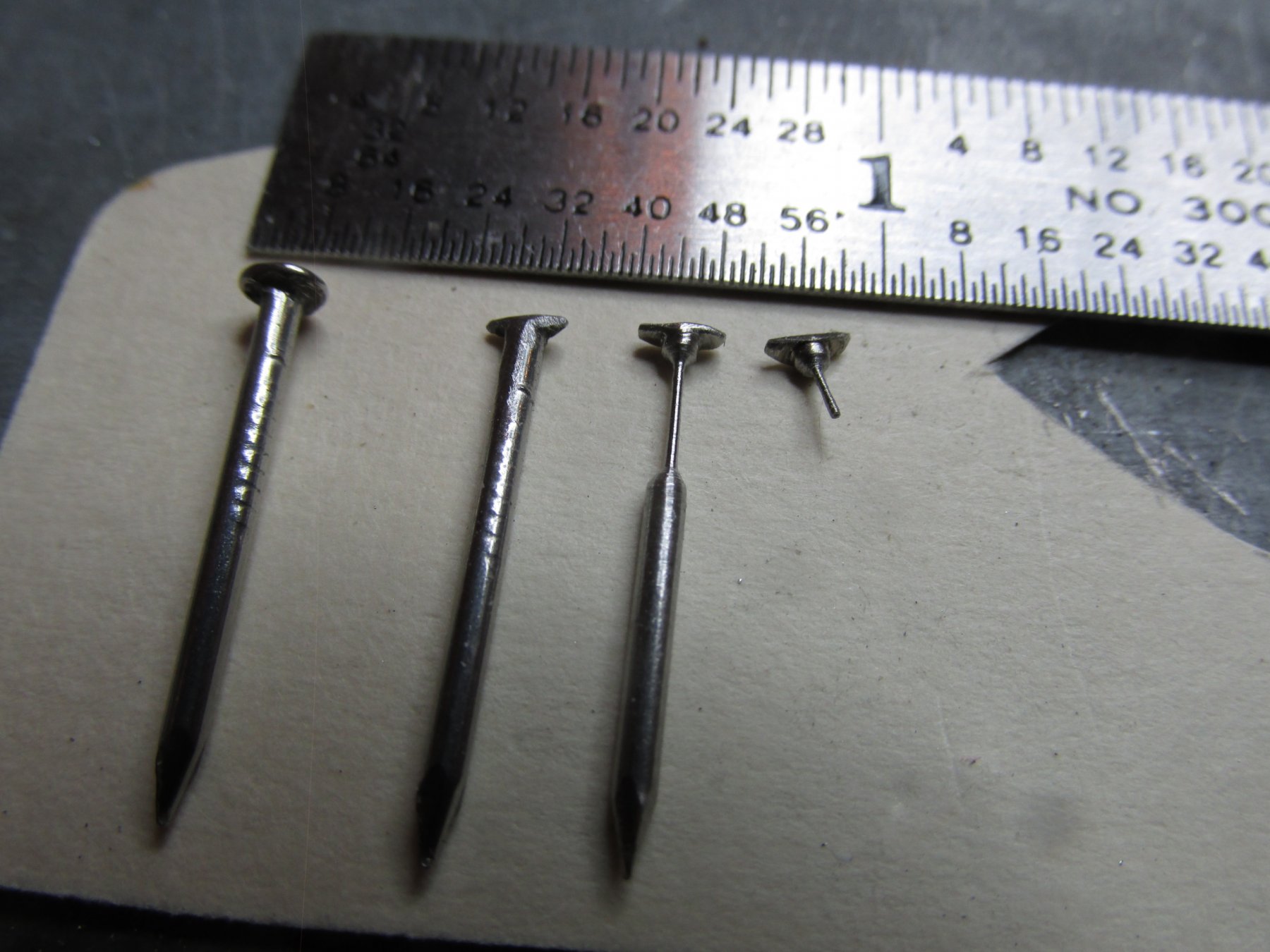
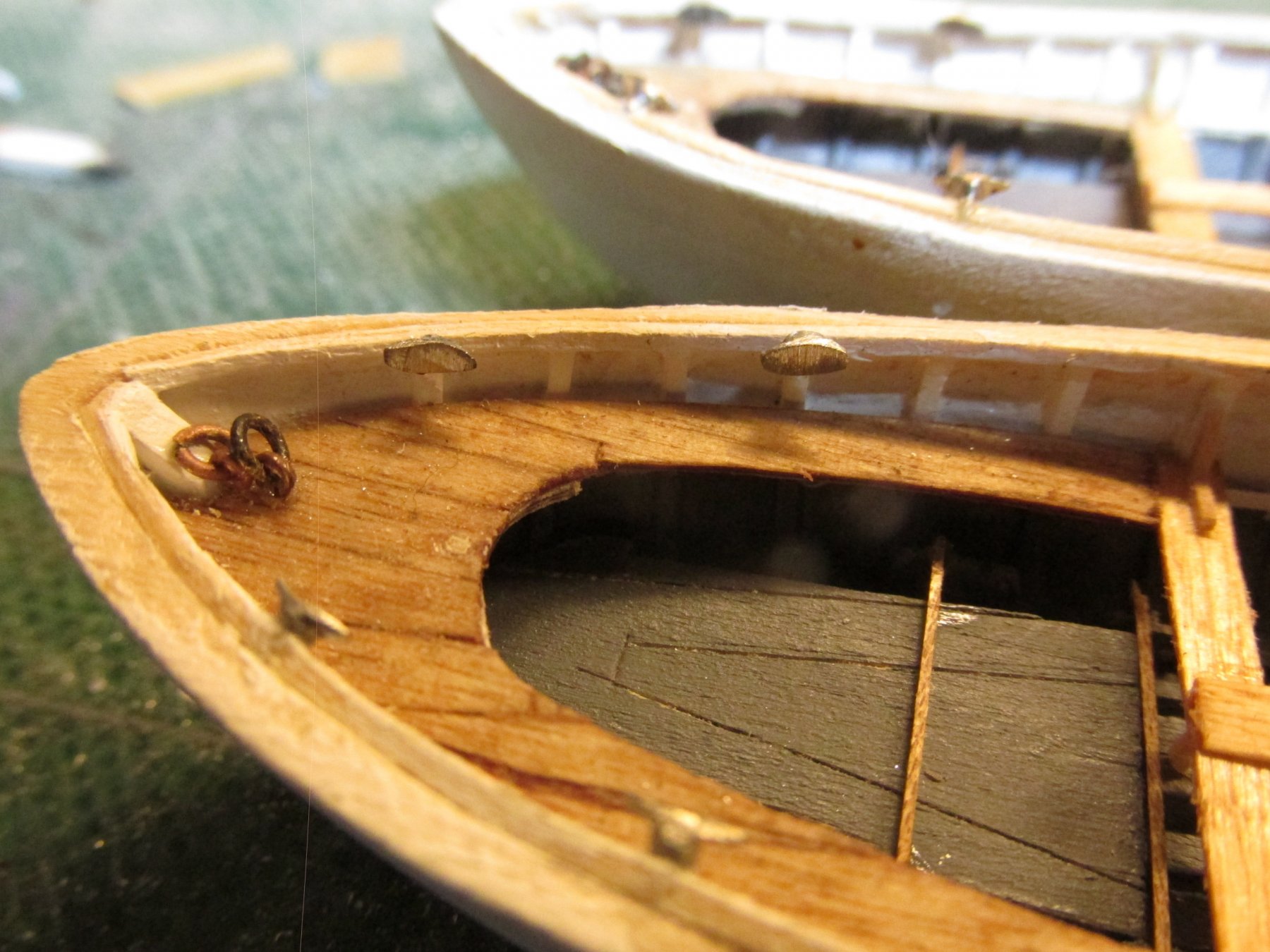
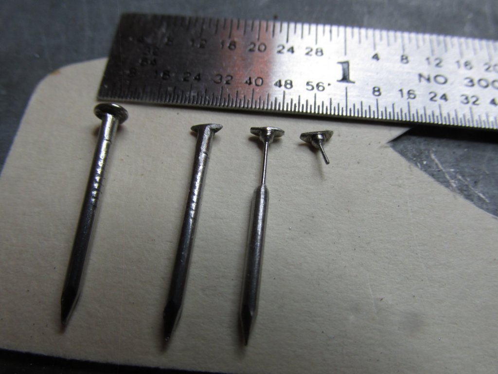
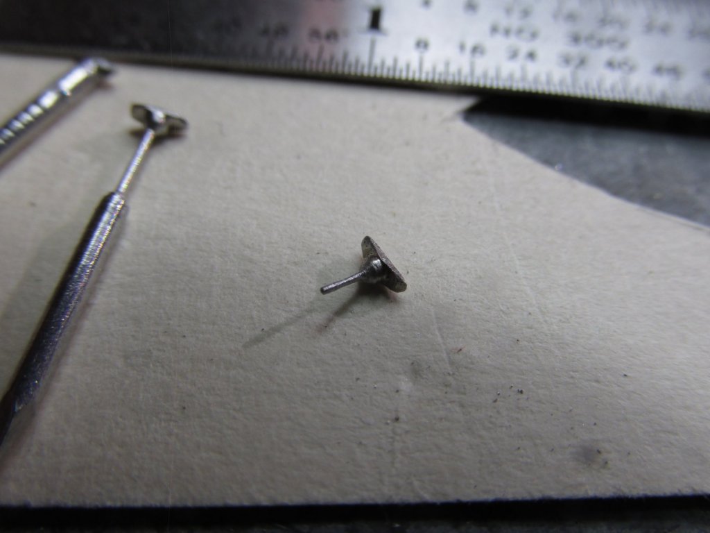
Whaleboat Steering oar oar-lock Unlike the gig, the whaleboats have an oar lock on the port side for a steering oar. Following xKen’s lead, the oar lock was made by twisting 22-gauge wire tightly around a nail to form a loop at one end. I then silver soldered the twisted wire and filed it to simulate a solid shaft. The loop was cut and form into a U-shape. According to the plans, the lock was to be fastened to the inside face of the rail with a bracket. But due to the scale, I elected to just drill a hole into the rail and inserted the lock with a spot of CA.


-
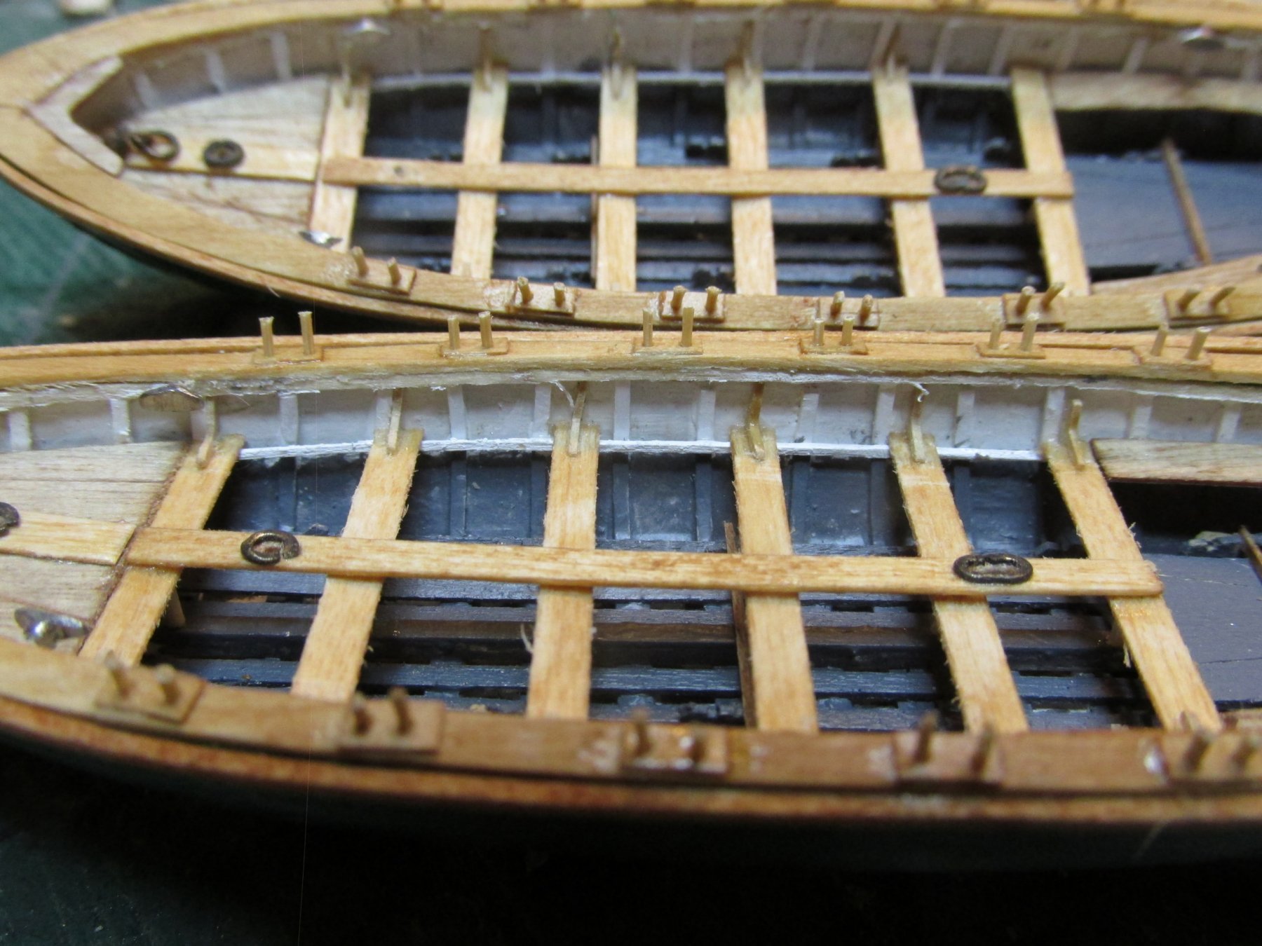
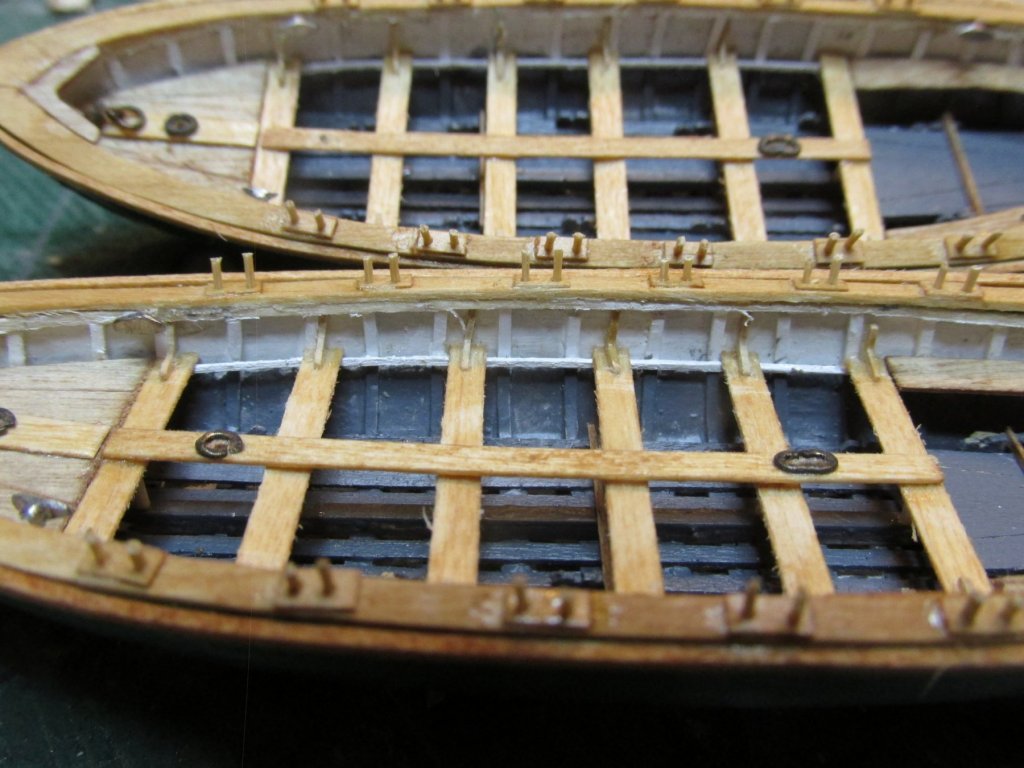
Whaleboat Rails, Knees and Thole Plates The rails were made from 1/64” boxwood. The bow and stern knees, as well as the thole pin plates used 1/64th plywood (for its strength).

-
Whaleboat Rails, Knees and Thole Plates The rails were made from 1/64” boxwood. The bow and stern knees, as well as the thole pin plates used 1/64th plywood (for its strength).
-
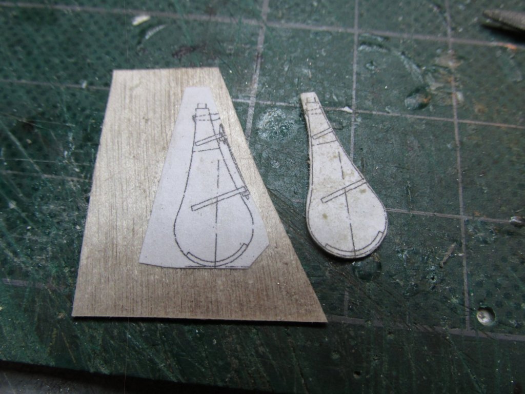
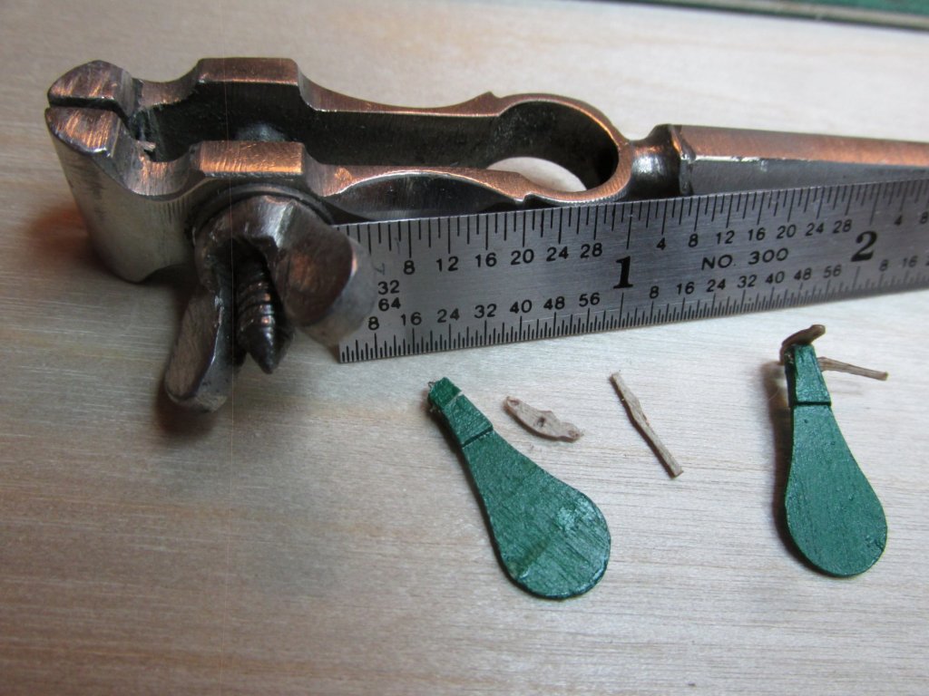
Whaleboat Rudders Using the US Navy Plans, the rudder plans were made into templates and rubber cemented to 1/64” plywood. Because most the parts were to be painted, the plywood was used for its strength. Like the gig, the rudder was made of four components: the main rudder blade, the re-enforcement plates for the tiller, the tiller, and the yoke. The tillers and yokes were stained. The rudder assembly will be installed later. You will note in the last picture my hand vise (holding up the ruler) which I used to file and shape the tillers and yokes.
-
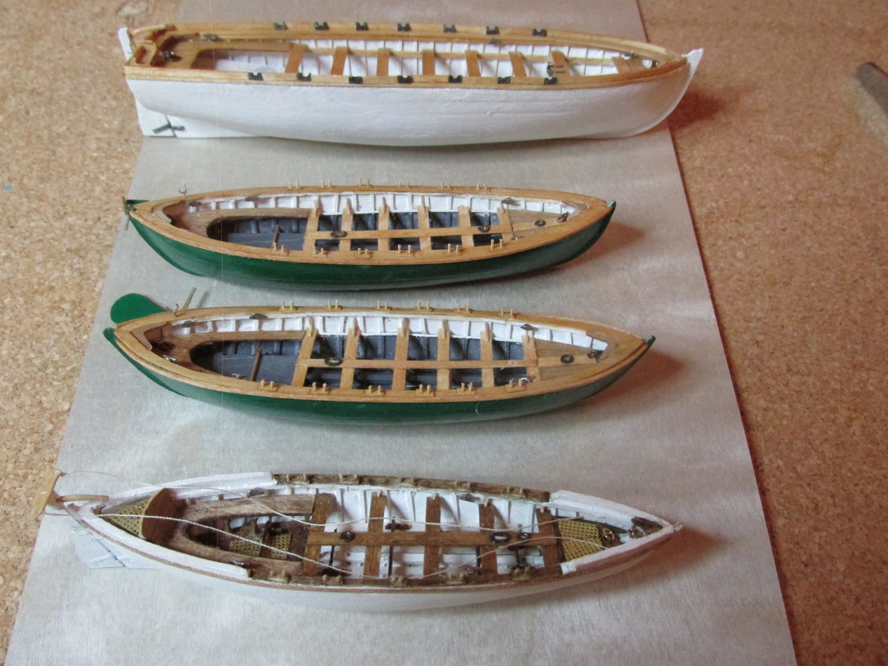
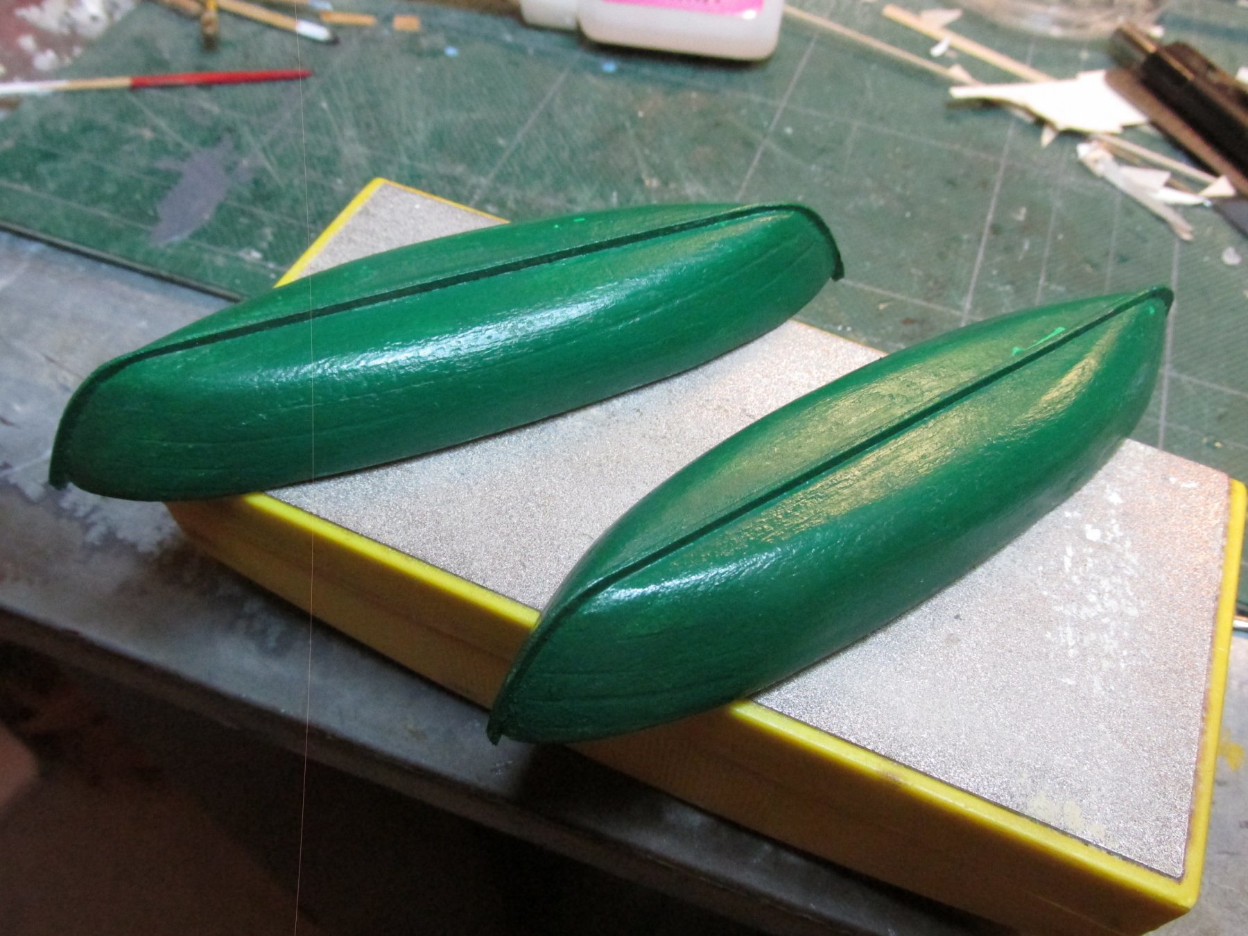
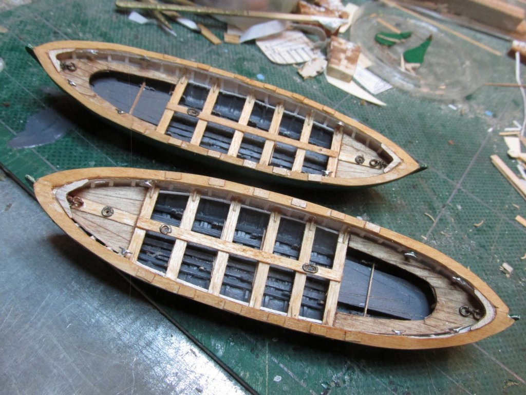
Whaleboat Paint Job Using the paint from the paint package I purchased from Model Expo for this kit, I painted the hulls dark green. The first thing I noticed was that the paint dries very quickly both on the models and on the brush. This is some sort of water solvent paint at least for thinning and clean up. I found that I had to add water to the paint to make it flow better on the hull surface but that reduced the its coving effect of the white primer (also from Model Expo’s paint package). Because it dried so quickly, the thickness of the paint on the surface would vary. Because of that, I let the paint dry 24-hrs and gave the surfaces a very light sanding and applied a second coat. It improved, but I still did not like the effect I was getting. Not only that, these hulls are supposed to be somewhat glossy, whereas the painted dried flat. So, I bit the bullet and purchased Model Master Green Gloss, an acrylic paint. After another light sanding of the hulls, I painted them with the acrylic…much better. I don’t know much about the different types of paints, their pros and cons, the do’s and don’ts, etc. Hopefully I haven’t violated any taboos on mixing paint types.

-
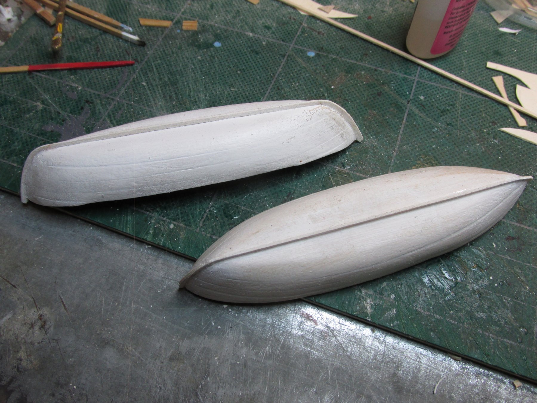
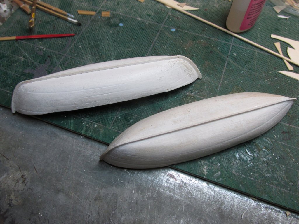
Whaleboat Keels It was time to install the keels. The kit called for a cross section of 1/32”w x 1/16”h. Per the US Navy plans, I figured it to be 1/32” x 3/64” not that anyone would notice. I cut some stock boxwood to my dimensions for the straight length on the Byrnes saw. I cut to size the curved sections of the bows and sterns from a cardstock template based on the actual model, not the plans. Once glued into place, they were painted with white primer.
-
With such a beautiful model, how are you going to display it? Hopefully you won't just put it on a shelf to collect dust. What are your plans?
- 481 replies
-
- 1
-
-
- rattlesnake
- model shipways
- (and 1 more)
-
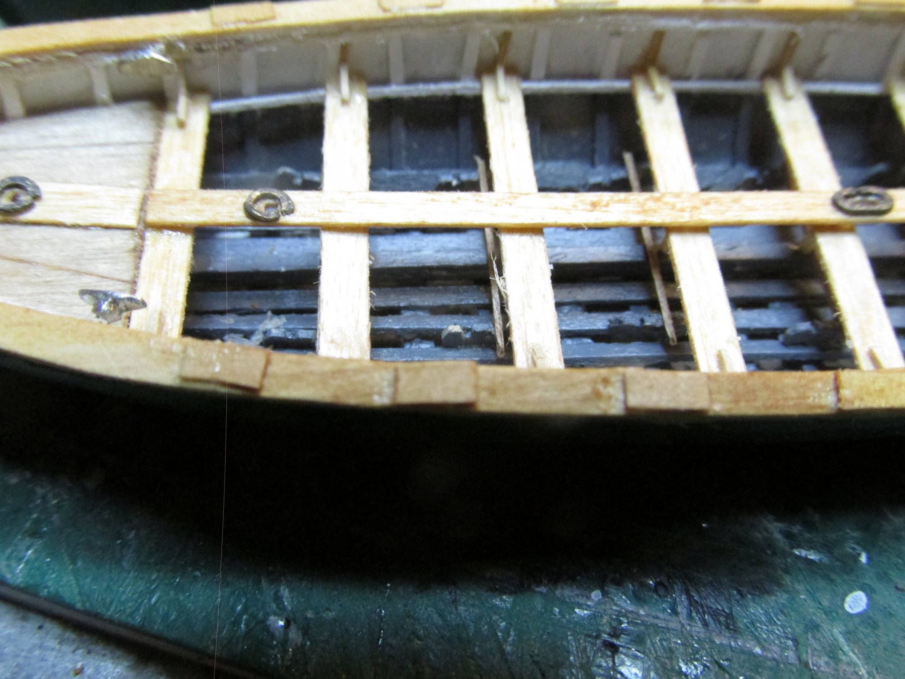
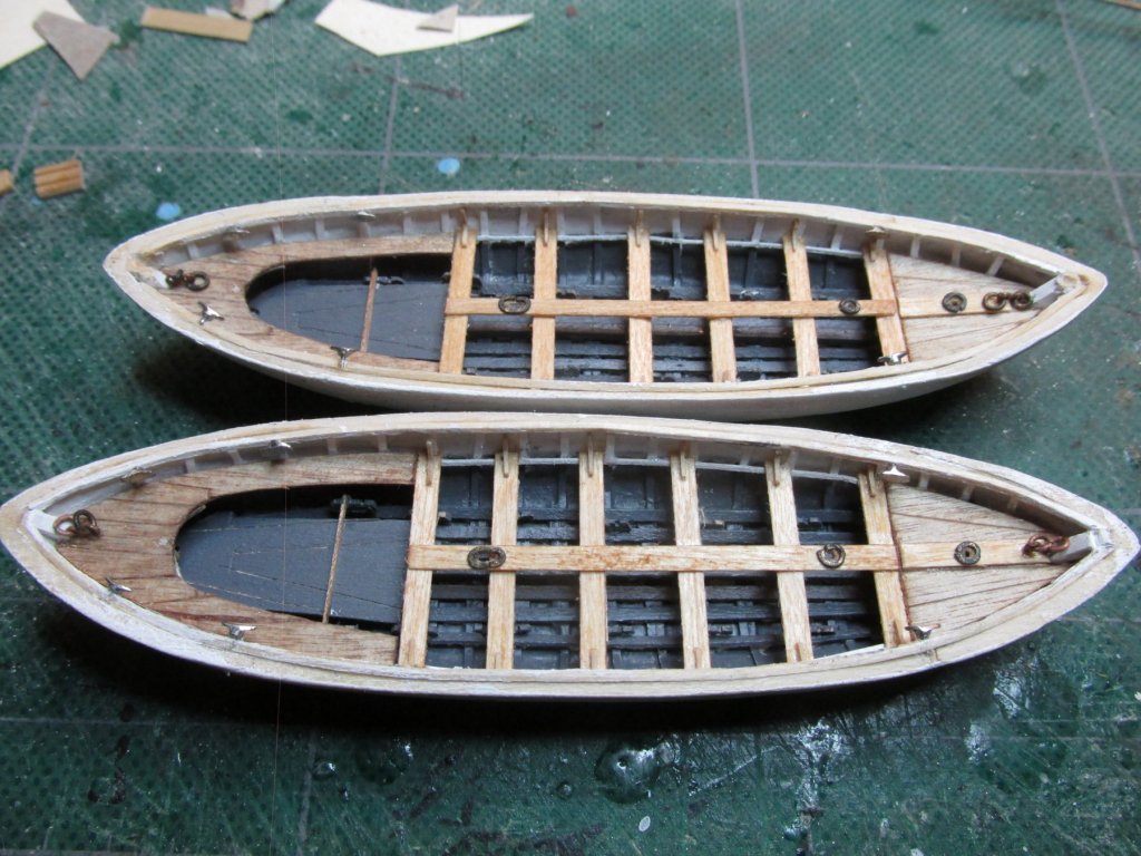
Metal Hardware Like I did with the gig, I used split-rings to create the various little metal pieces protecting the holes in the centerboard and lifting rings. Once more I used my poor man’s cleat making technique – no metal lathe, just files and a rotary drill

-
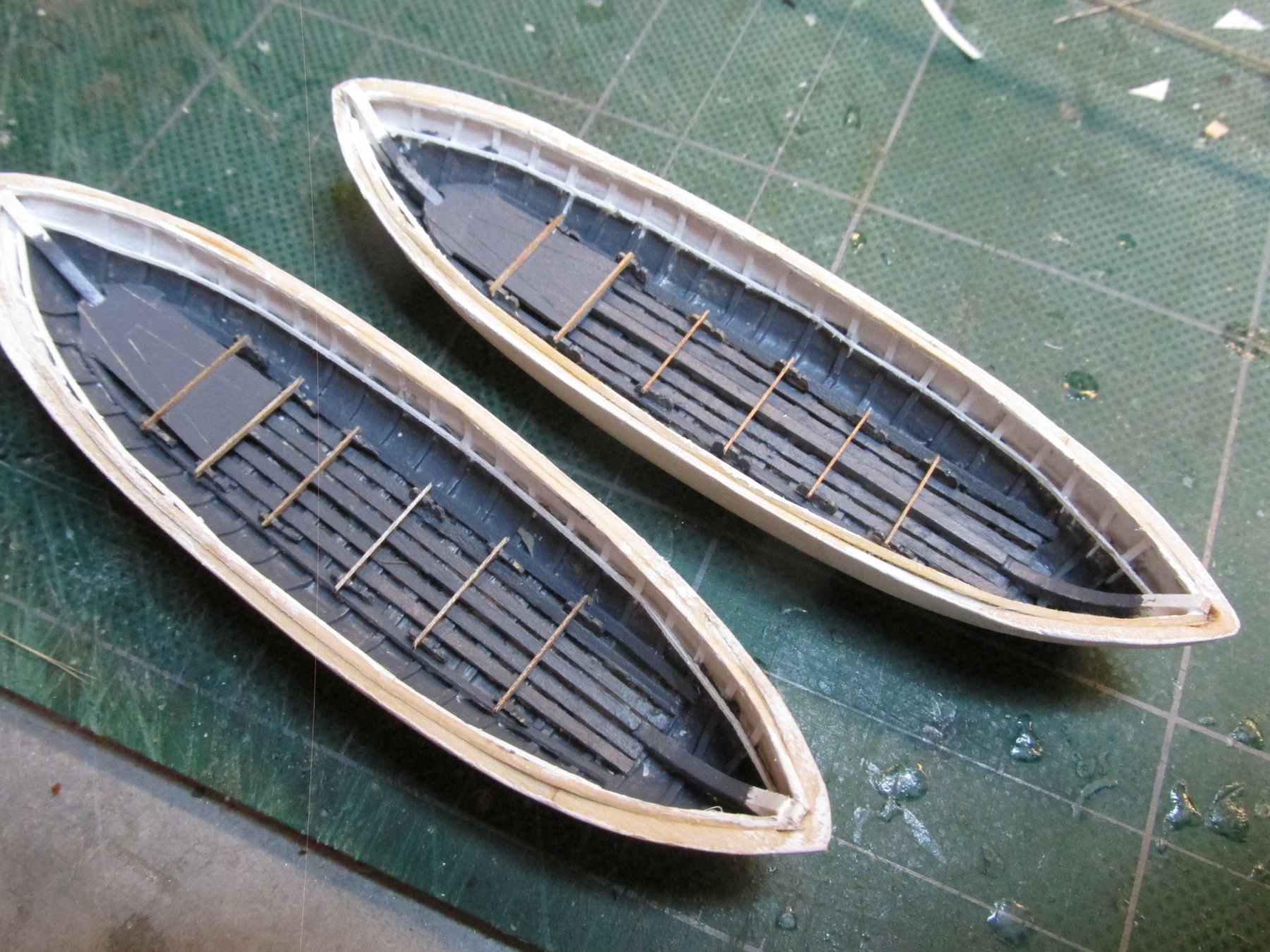
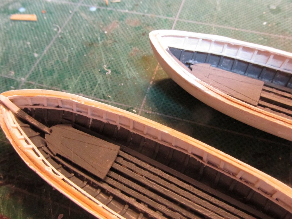
First off let me say Mom rode out Irma just fine. She lost power for four days, but she and her temporary 24-hr aid survived with only minor discomfort. And, it appears that Maria will leave her alone. Whaleboat Stern Benches and Aft Decks I attempted without success to create the stern U-shaped bench from straight planks. I thought I would use the plans as a pattern cutting, fitting, and gluing the pieces so that I could insert the whole assembly as a unit. That didn’t work because the gluing surface were the edges of the planks and they would snap apart just looking at them. I tried assembling them in situ, but there was no support for the planks to be attached to during construction. I admitted defeat, and used 1/64” plywood and with an X-acto knife, etched in the board marks. Then I stained it which brought out the etched lines. Note: these images are dry fits.
-
Work on the model may slow down a bit due to hurricane Irma. As I have mentioned in past posts, I visit my Mom in Florida every couple of months or so. She is now in the crosshairs of the storm. All my relatives who could have helped her, were too far away. I tried to get someone to board her condo windows up, but there was no plywood to be had. Luckily, my Sister (lives in Connecticut) managed to get someone with experience with elder care (she’s 99 years old) to stay with her 24-hours-a-day till the storm subsides. They are going to hunker down and hold on to it other. I wish I could have done more, but I’m 600 miles away. By that time, I’ll be feeling the effects here in South Carolina. I don’t know what kind of condition Mom or her condo will be in, whether she will be able to stay there, or will have to come to live at my place for a while once the worst is over. It’s going to be an interesting and bumpy ride
-
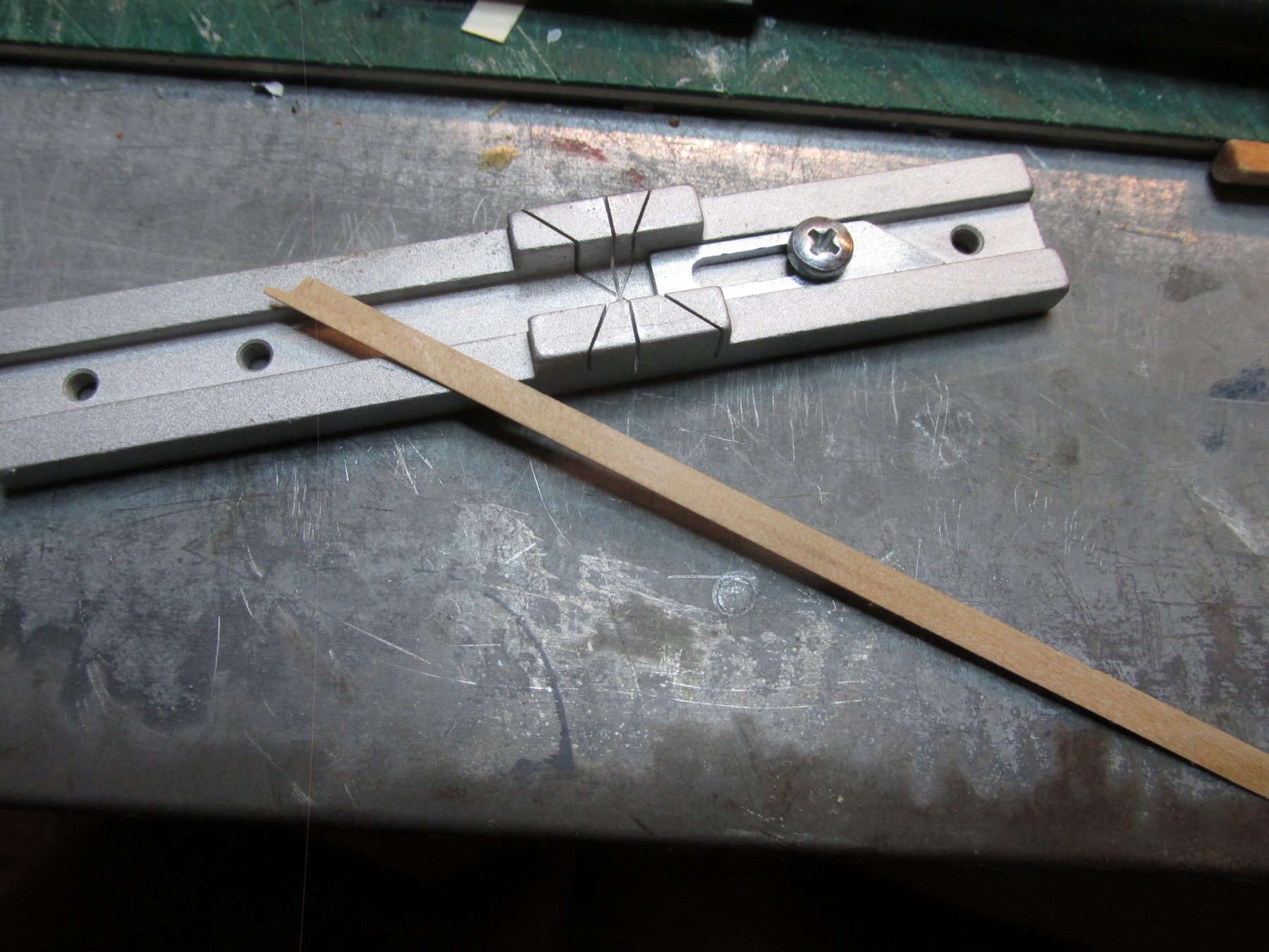
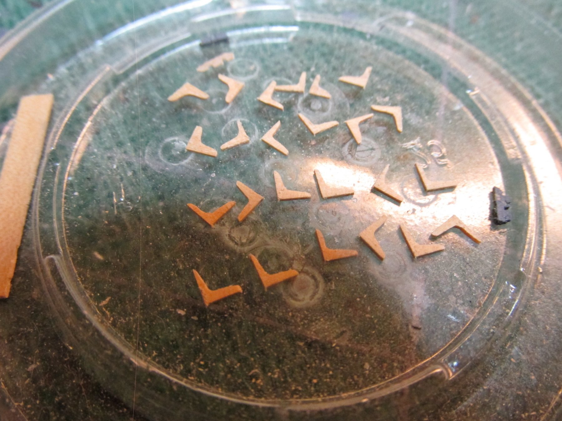
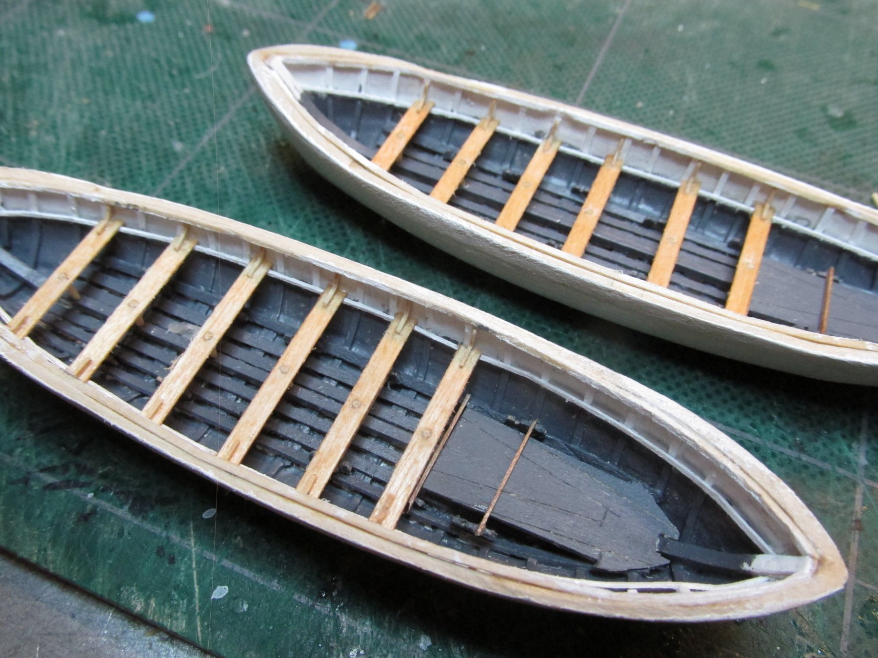
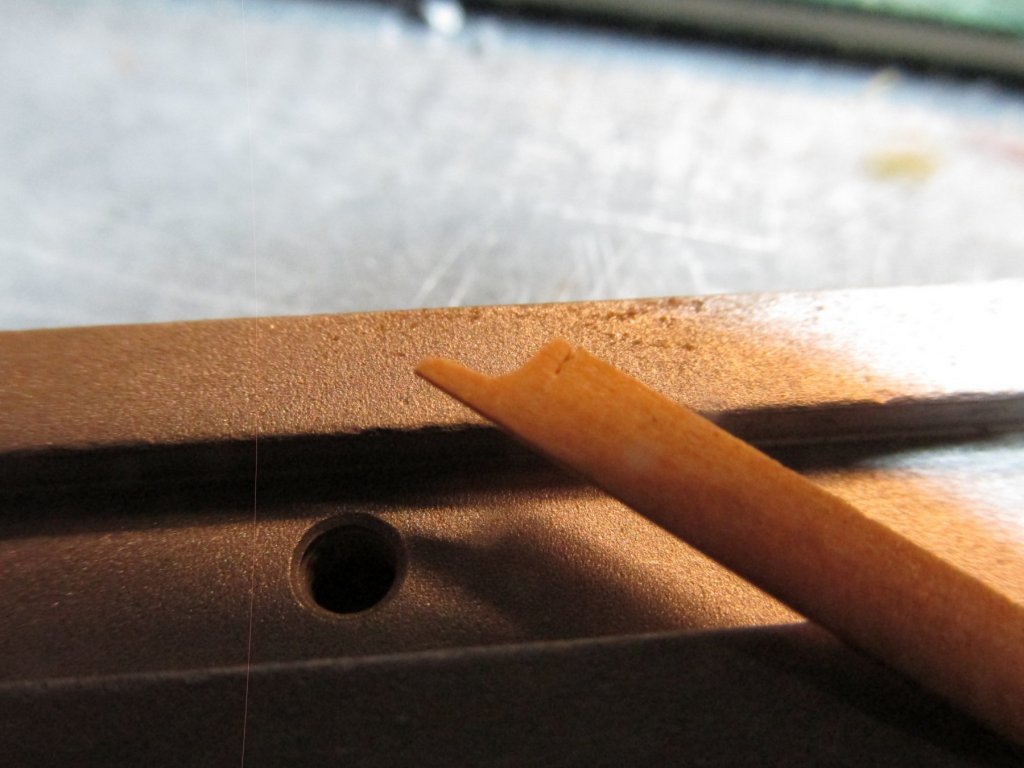
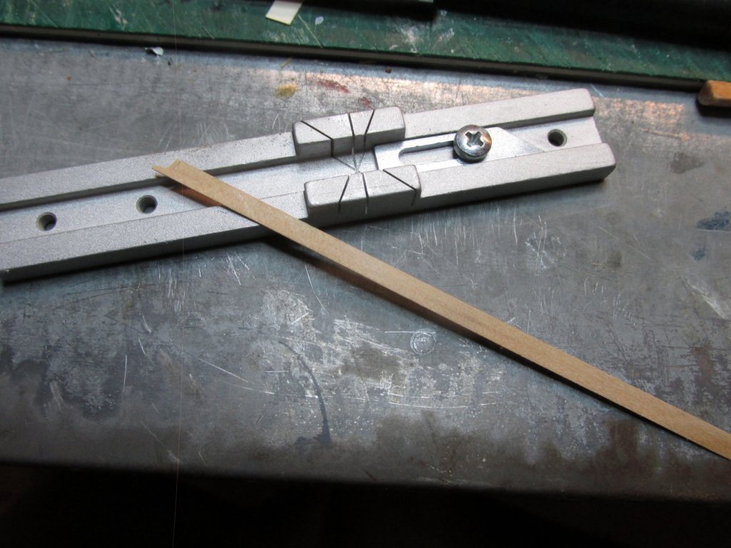
Whaleboat Thwarts I decided to install the thwarts next. Because the thwarts are not painted, I used 3/32” x 1/64” boxwood. These were cut to fit and rested on the riser installed earlier. The thwart stanchions are 1/32” in diameter and were made from bamboo pulled through a drawplate just like the gig. The thwarts also have knees which attach to the top of the seats. These were made from 1/8” x 1/64” boxwood. The knees were first carved on the wood stock then cut off using the razor saw and miter. The miter was used more for creating consistent lengths than squareness of cut because I had to file off an additional fraction of wood so that the legs of “L” shape was a bit more than 90 degrees to conform to the shape of the hull. These were then glued into position.


-
Very nice. If you hadn't brought the problem to our attention, we would never had know a repair was made. Good job. Jon
- 481 replies
-
- 1
-
-
- rattlesnake
- model shipways
- (and 1 more)
-
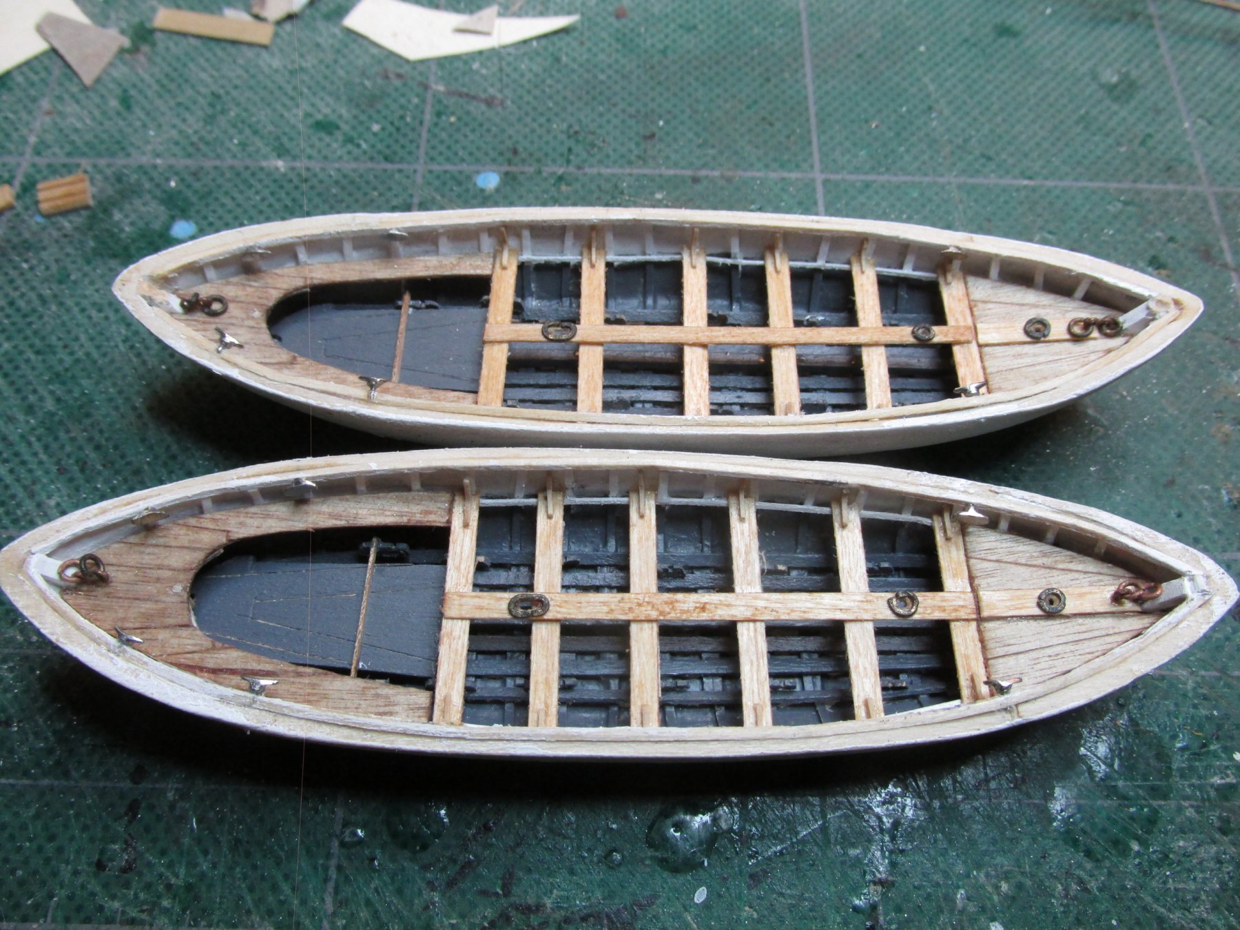
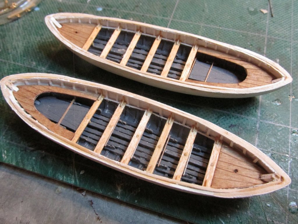
Whaleboat Foot Rests Just like in the gig, the foot rest were made in the same manner from 1/64” stock material. This time, the two position brackets were paint grey. I left the foot rest itself bare because I thought that paint would not last very long under the wear and tear of rower’s feet and they probably were replaced as needed. It also offers a little contrast.


-
The sole was made from a single piece of 1/64” plywood. Lines were etched in with an X-acto knife to represent the removeable hatch. It was painted and glued into position.
-
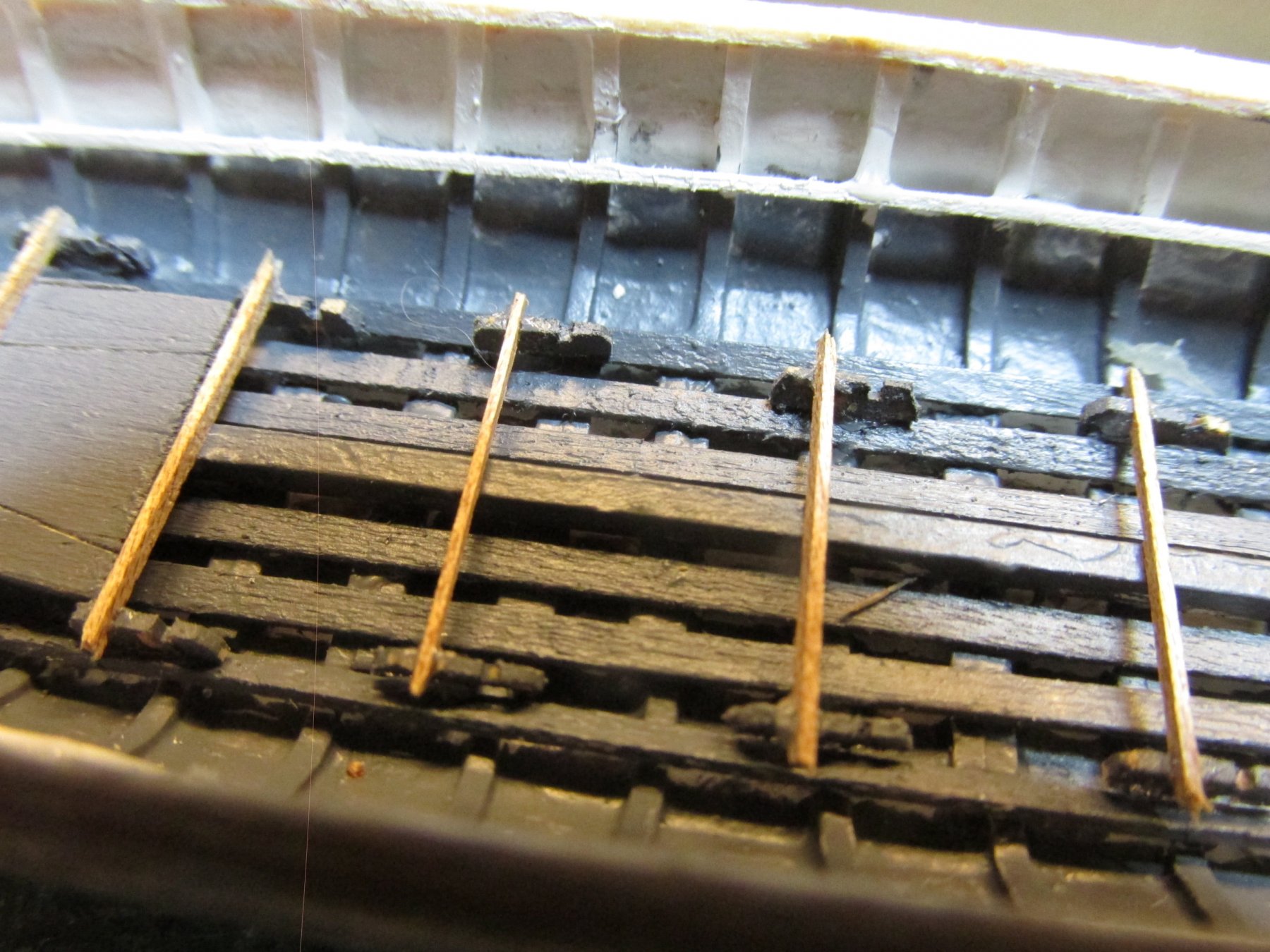
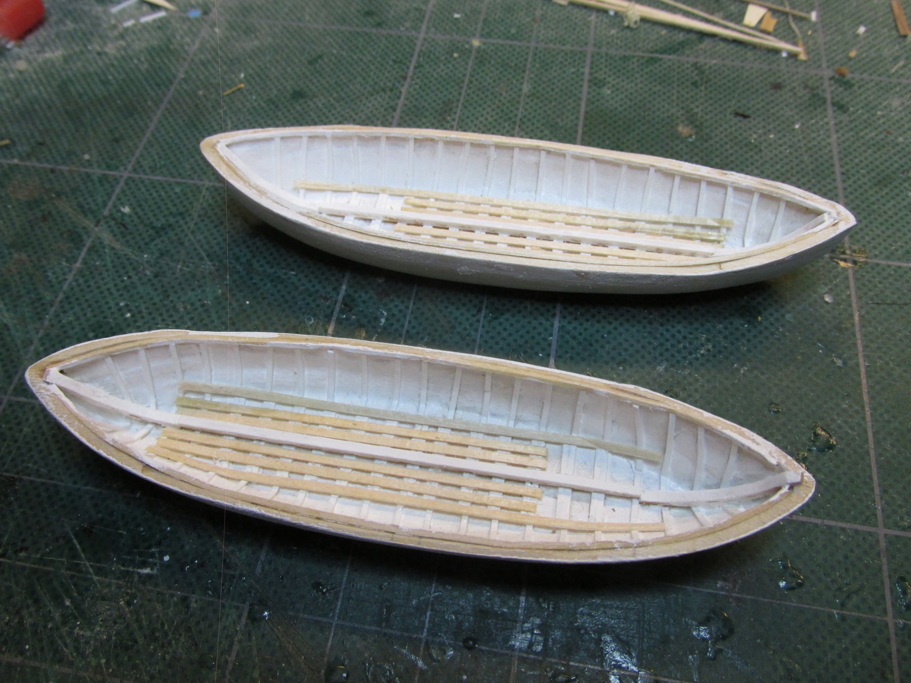
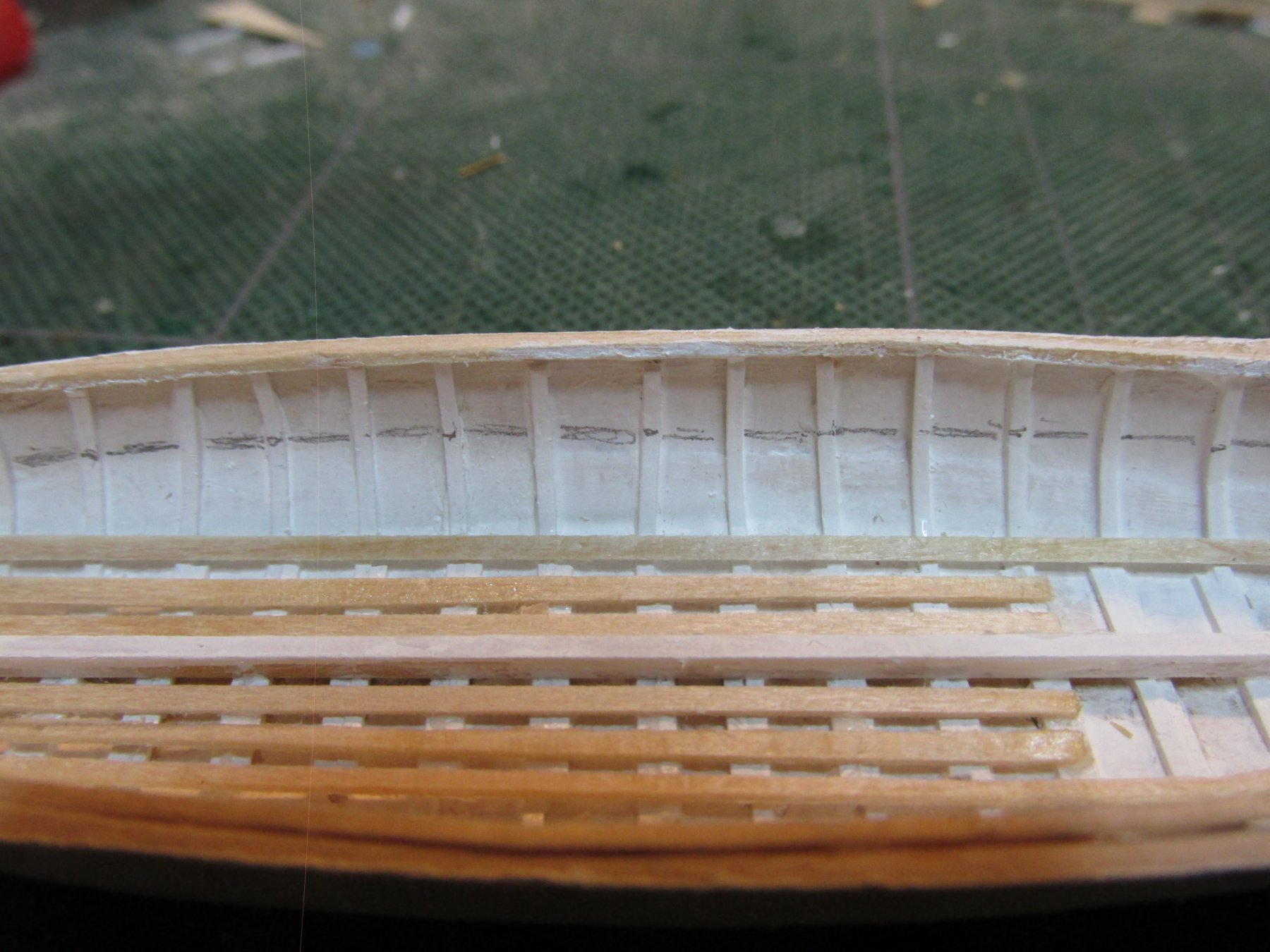
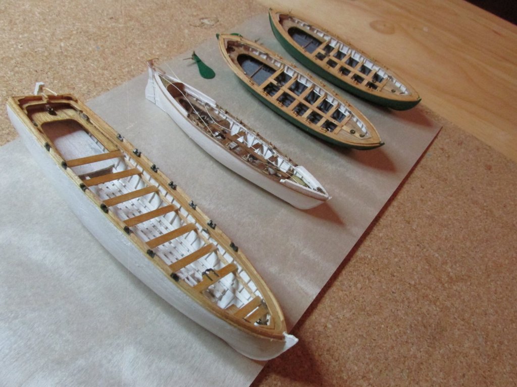
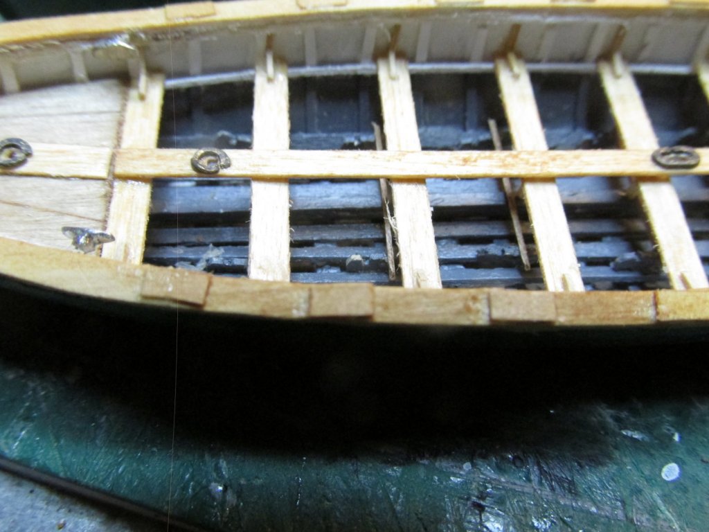
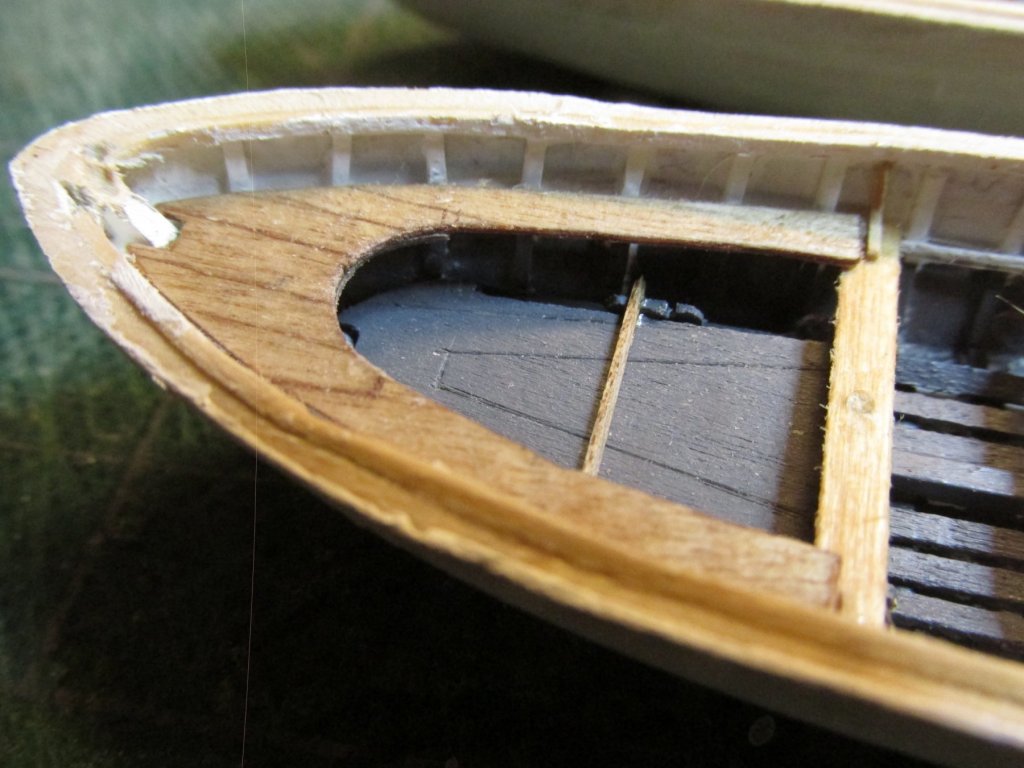
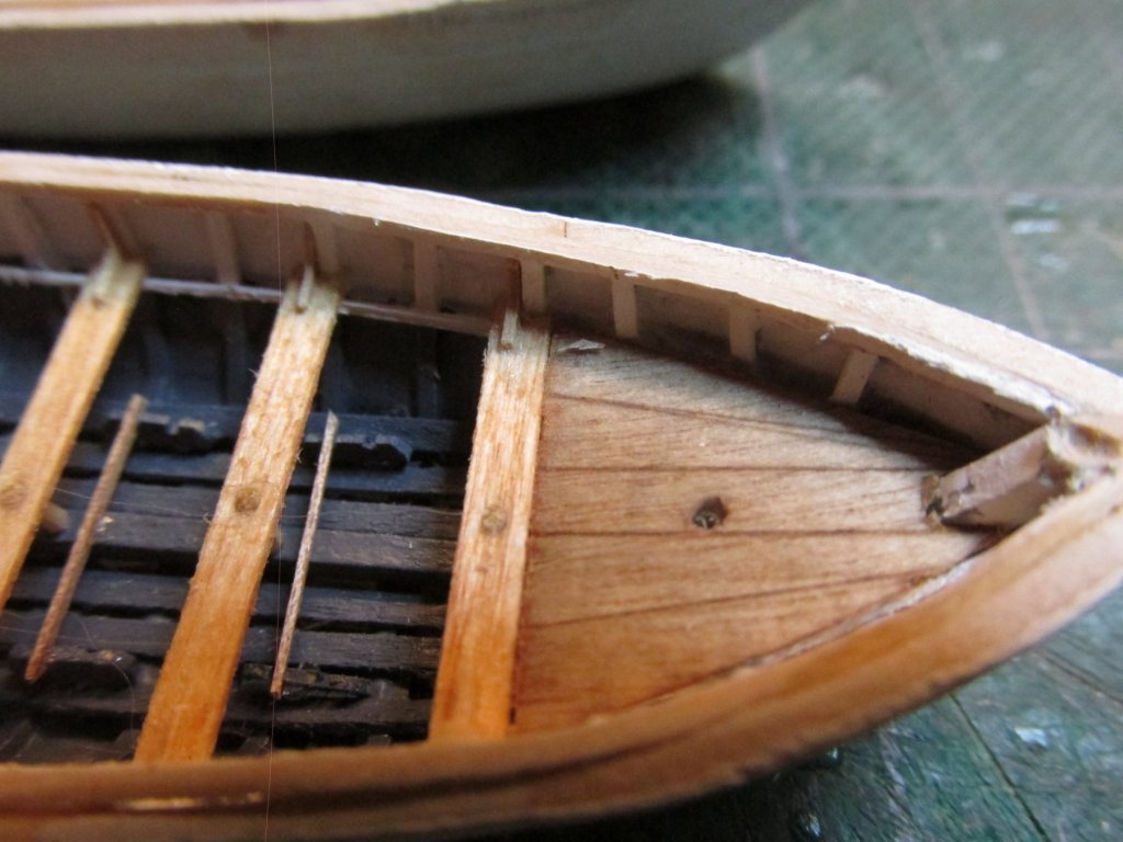
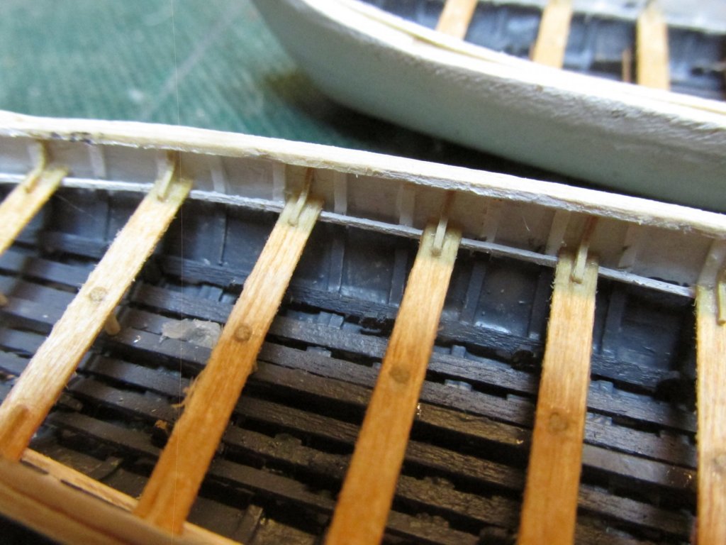
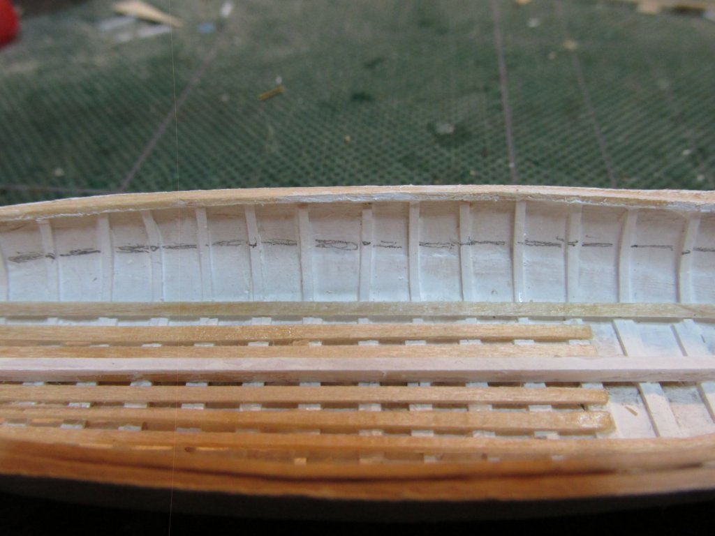
Whaleboats Just wanted to say that this week (Aug 21, 2017) has been interesting. I got to see the eclipse as I was right smack dab in the middle of the totality just west of Columbia SC, about an hour from my home (using back roads to avoid highway traffic). It truly was a spectacular sight. My friends and I could not have asked for a better day. However, the next afternoon, I discovered that someone had rammed into my mailbox with a vehicle and smashed it into three pieces and damaged the one next to me sometime earlier in the day. I spent Wednesday removing what was left of the old mailbox post, and putting in a new one. If it’s not one thing, it’s another in the life of a home owner. When we last saw the two whaleboats, I had left them as a simple hull with simulated ribs painted with white primer. Per the Hunt practicum, he gave the builder a choice of priming the hull and ribs and then adding the flooring, or adding the flooring and then painting a more difficult structure. Since I had already primed the hull and ribs earlier, the flooring was added and then a coat of white primer was then applied to it. Ideally one would want to glue the bare wood pieces to a bare wood surface and not a painted one. On the other hand, a coat of gray had to be applied to the inside of the hull as well and I would still have to paint the hull and ribs again. Eventually all was glued and painted. The plans called for the use of 1/32” x 1/64” risings but due to the fragility of the stock and the low probability anyone would notice, 1/32” square painted white strip of basswood was used and positioned at the border of the white and gray paint inside the hull. The rising will eventually support the thwarts.

-
OK, now you are really showing off 8-). I would have never thought of using blackboard chalk as a carving material. Fantastic job. Too bad your viewers will be leaving their nose prints on the display case (you are making a display case, aren't you?) as they try to see the intricate detail of the carving. Your skills never cease to amaze me. Wow! Jon