


JSGerson
-
Posts
2,480 -
Joined
-
Last visited
Content Type
Profiles
Forums
Gallery
Events
Posts posted by JSGerson
-
-
Bowsprit Horses and Fore Topmast Staysail Netting
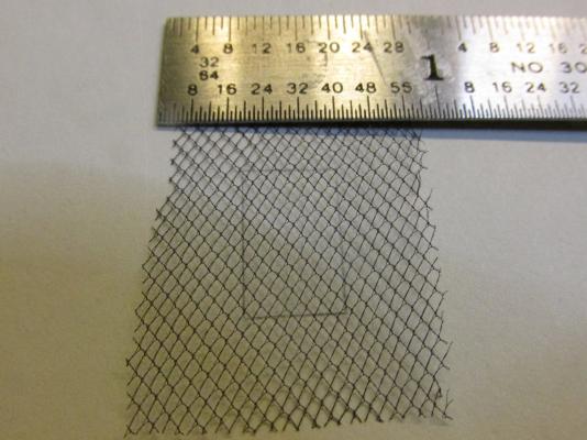
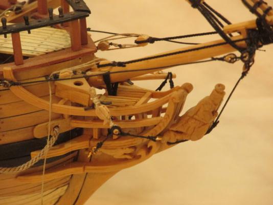
Continuing to follow David Antscherl, now was the time to create the bowsprit horses, and although not shown on any of my plans, the fore topmast staysail netting. The netting is used to store the topmast staysail and is located on the bowsprit horses between forestay and the foretopmast preventer stay. Mr. Antscherl was very clear that the diagrams in Darcy Lever’s The Young Sea Officer’s Sheet Anchor, Lee’s The Masting and Rigging of English Ships 1625-1860, and Peterson’s Rigging of Model Ships¸ were incomplete. They only showed the initial zig-zag construction of the netting and not the final result which was a diamond shaped netting. David went so far as to reproduce this netting for his model; I, being of sound mind and body, elected not to. Instead I bought some tulle in black and off-white at Hobby Lobby. It’s a sheer often stiffened silk, rayon, or nylon net used chiefly for veils. It’s not perfect, but it was all that I could find in my area. Both pieces set me back a grand total 0.30 cents for more material than I will ever use in a lifetime.
-
Martin, I'll be heading out next Tuesday and checking in Wednesday. I'll see you Wednesday or Thursday!
-
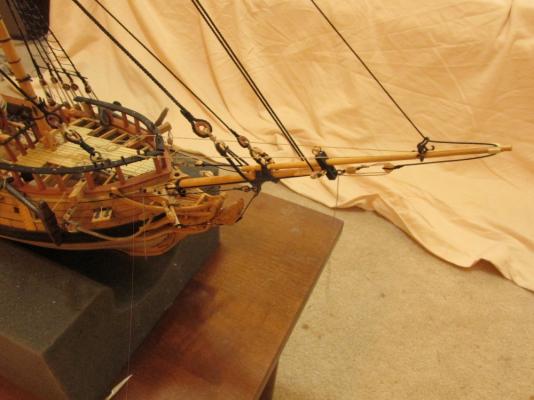
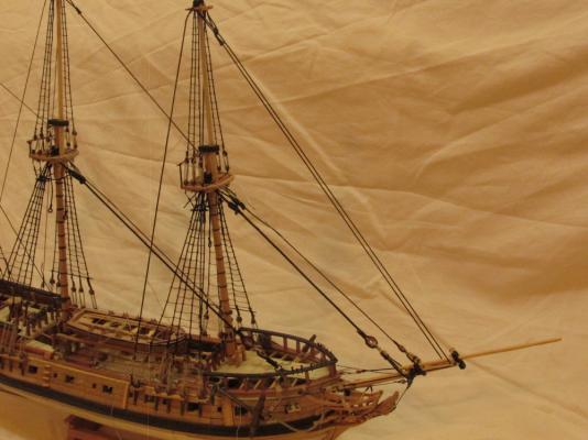
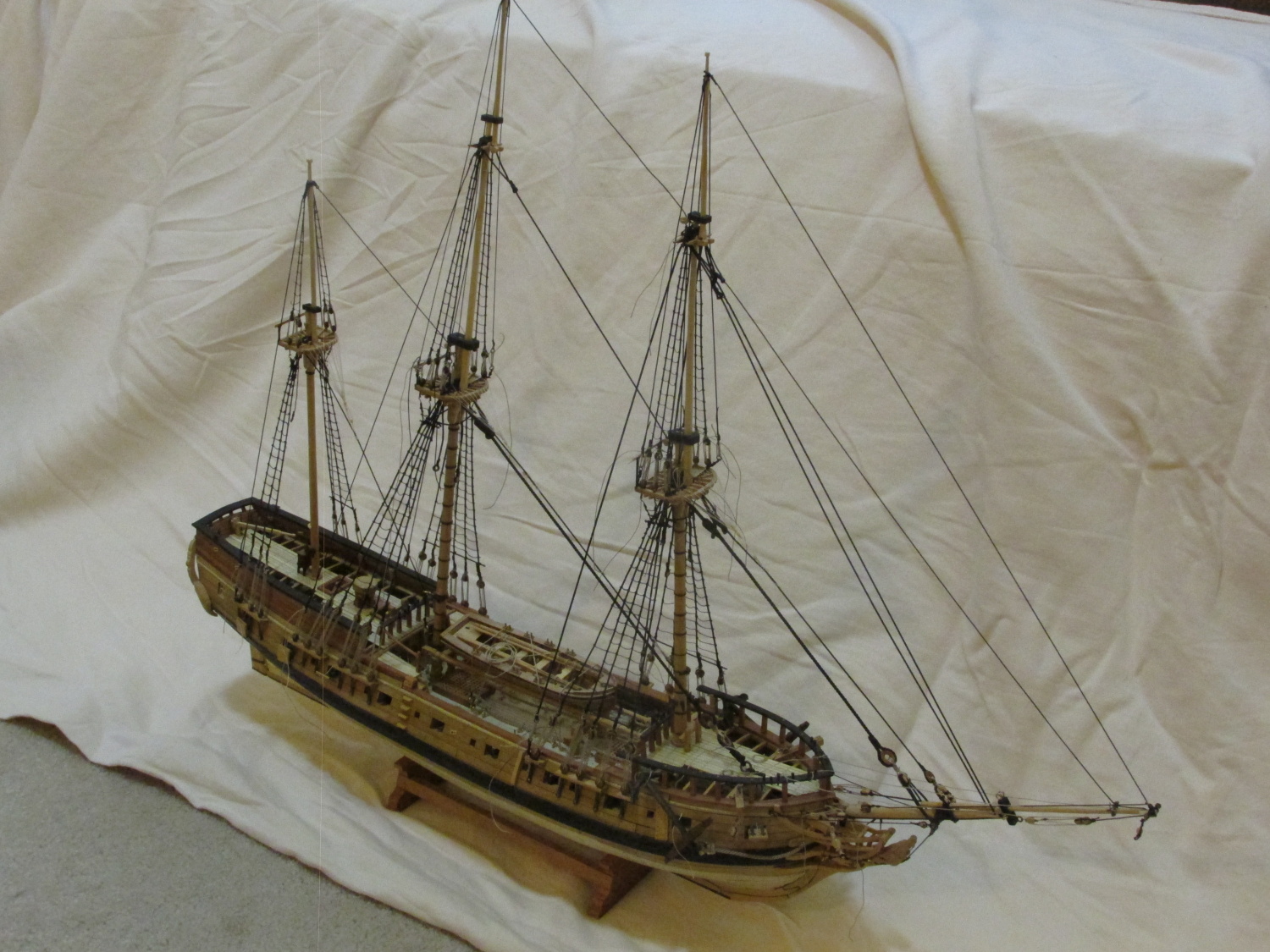
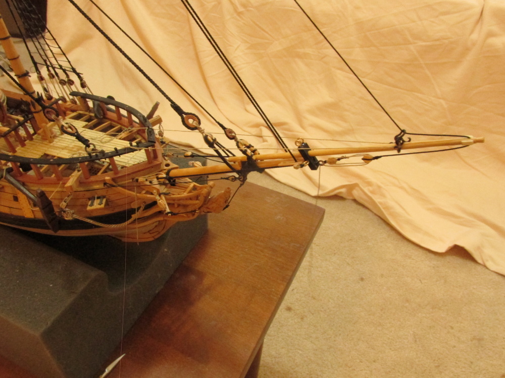
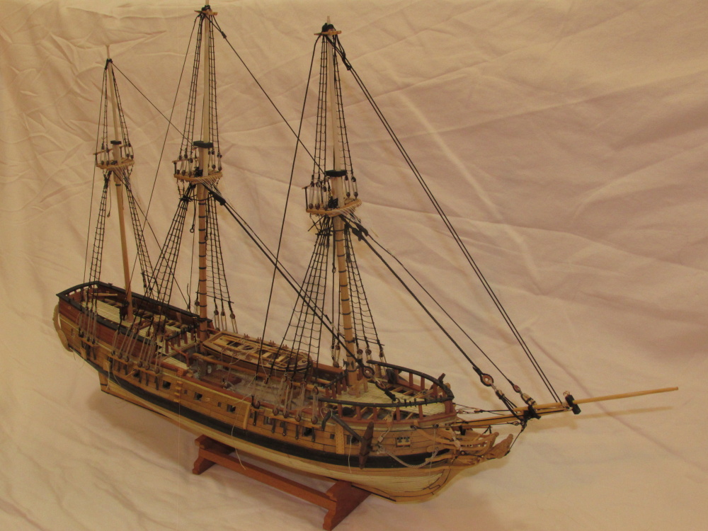
This is how my Rattlesnake looks now:

- GuntherMT, mort stoll, Jack12477 and 2 others
-
 5
5
-
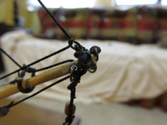
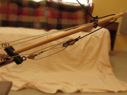
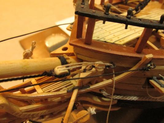
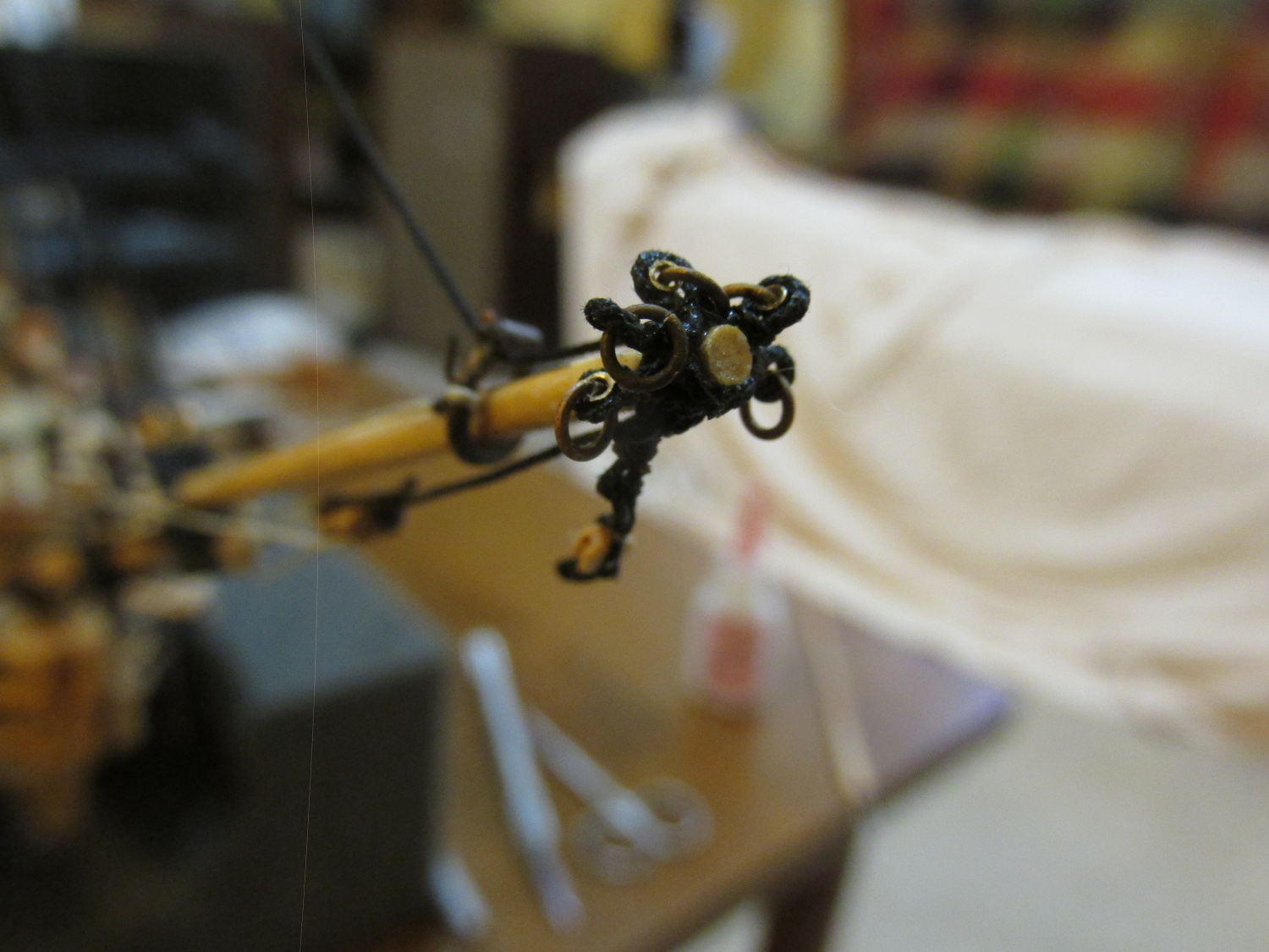
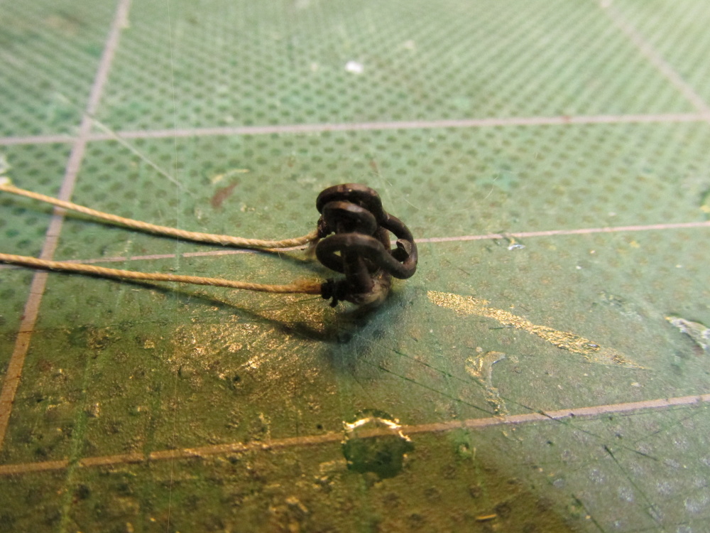
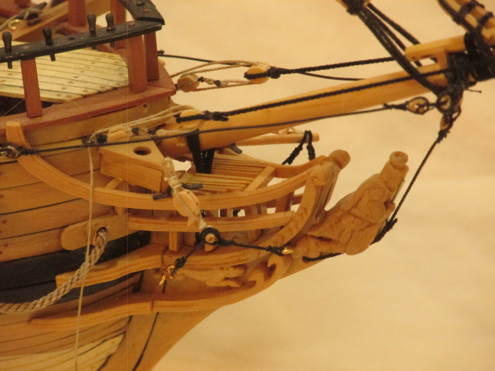
The first to be attached was the block assembly, followed by the double eyelets, and finally the triple eyelets. The block assemble was attached with a loop through an eyelet and pulled tight. The multiple eyelet assemblies had to be installed in steps. In actuality, the rope ends were spliced or lashed together which at this scale was impossible to do. First, an assembly was orientated to the proper position and then a touch of glue was added at the top to hold it in place. The two ends were cut so that they would just meet under the bowsprit and butt together. First one end the given a touch of glue and then the other was made snug and glued into place. The fourth item, the footropes was not added at this time but will be added later. That will be made from thick thread so there is just enough room left to secure it.

-
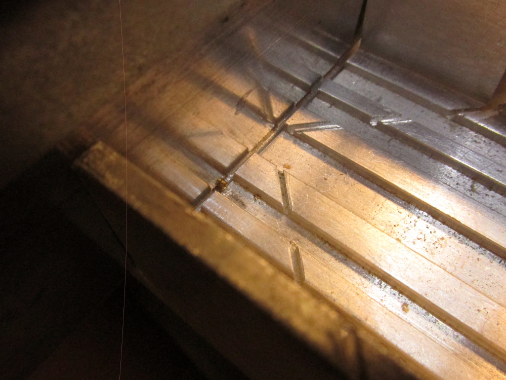
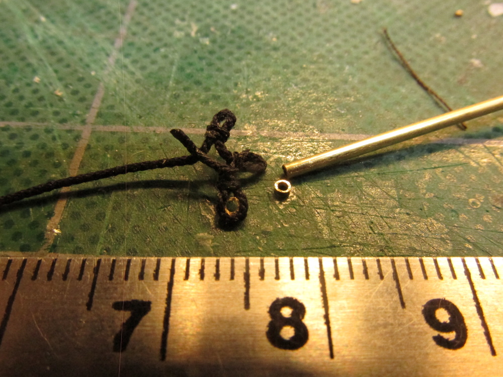
However I chose to follow Mamoli for the construction of these items, in particular the addition of thimbles in the eyelets. They were cut from 3/64” brass tubing. You can just see it against the saw blade in the 90° groove.


- Jack12477, GuntherMT, CaptainSteve and 1 other
-
4
-
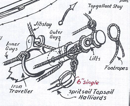
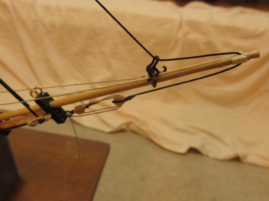
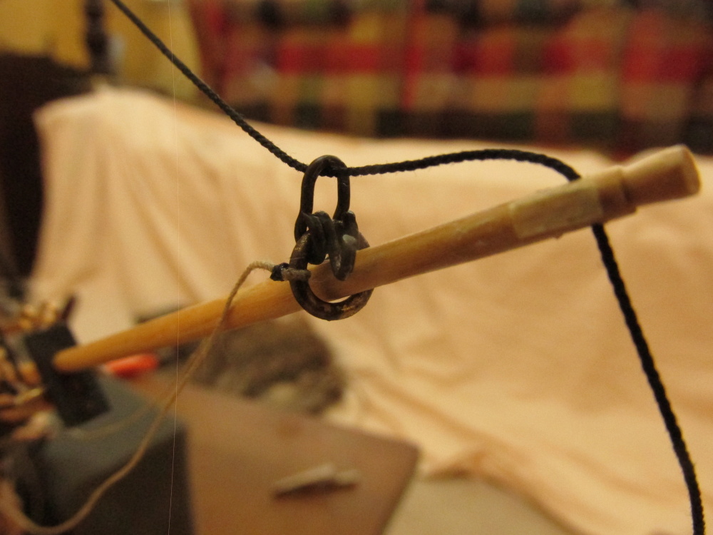
The Topgallant Forestay was next. It starts at a pair of deadeyes coming off the bow, goes through a ring attached to a thimble at the tip of the bowsprit and is attached to the top for Fore Topgallant Mast with a line eye slipped over the mast. But, in order to do this, one of the corollaries of Murphy’s Law is that “No matter what you have to do, you have to do something else first” had to be complied with. In this case, it was on the tip of the bowsprit. There are four items there and two of them had to be completed first. They were (aft to forward): Spritsail Topsail Halyards Block, Outer Guys (two eyelets), Lifts and Stay (three eyelets, and the footropes. The Mamoli plans show different portions on the bowsprit depending on what is being rigged. They also have a complete image but without all the detail. The image below is from Model Shipways. As with everything else, it seems nobody can agree on how things were done. The Mamoli plans show the order as: Lifts and Stay (three eyelets), Outer Guys (two eyelets), Spritsail Topsail Halyards Block, and the footropes. I chose to follow MS for no particular reason other than I like their diagram.

-
Thanks all, your flattery er... opinions are greatly appreciated.
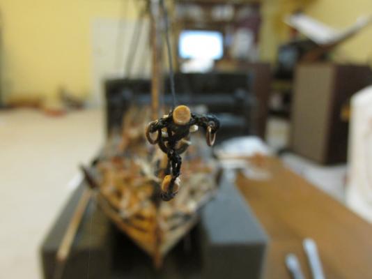
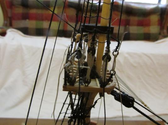
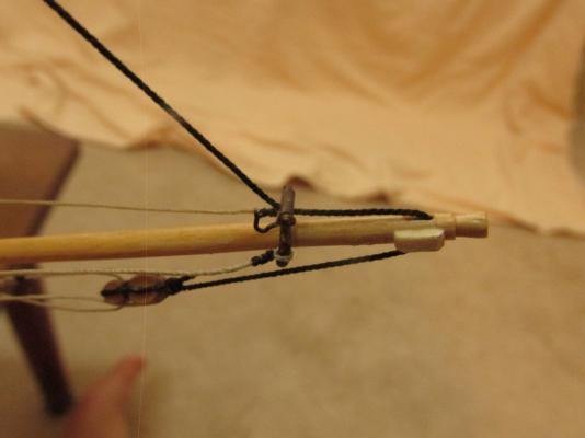
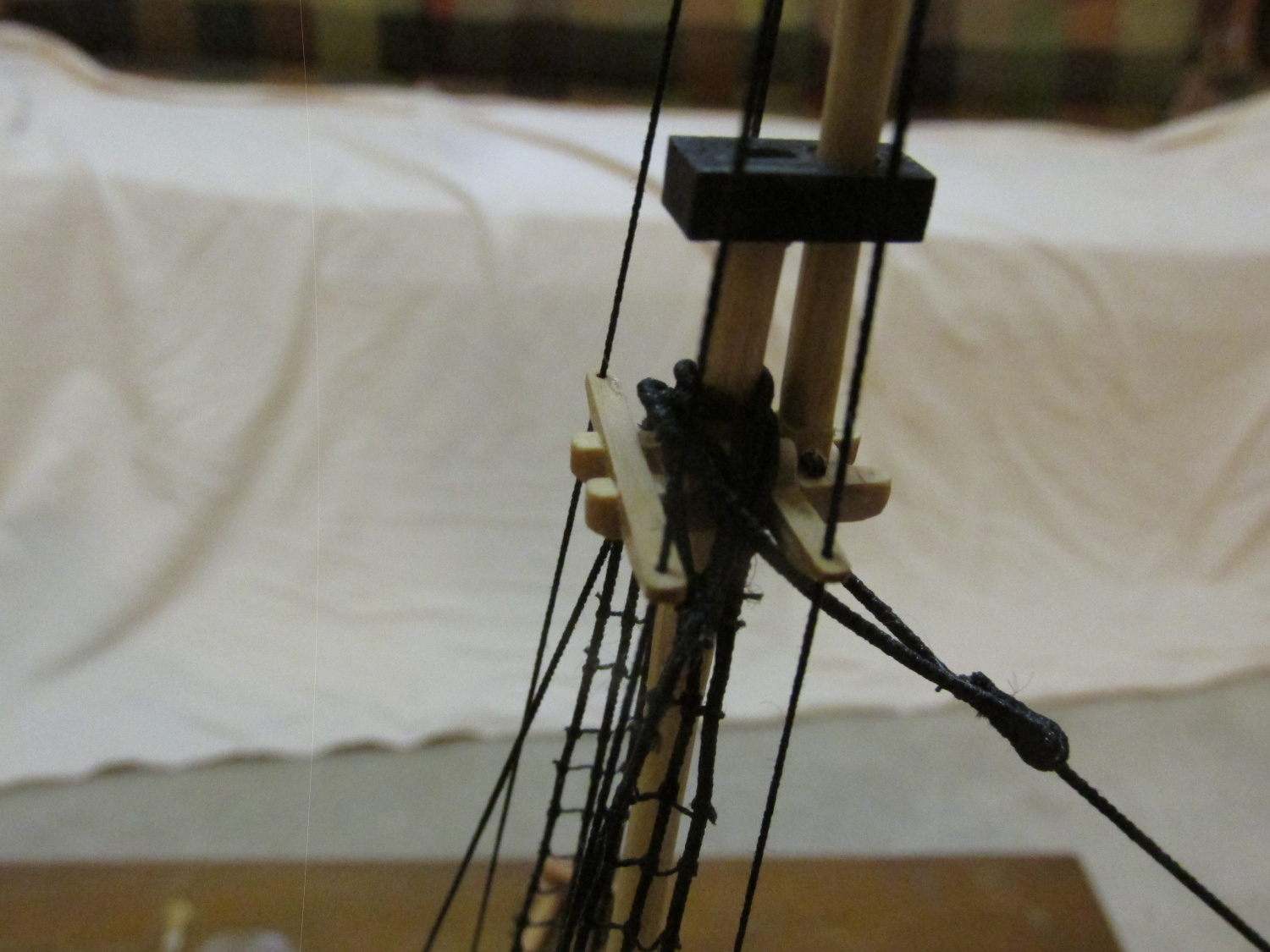
Finally, we come to the Fore Topgallant stays. The backstays start at the mast top, pass through a previous drilled hole through the cross tree, looped around the top of the mast, back through the crosstree and finally anchored at the top. The anchoring at the top is by lashed rings off of the outside deadeyes. The looping at the top of the mast is seized and both the ends and the loop were served. In the picture below, the lines have not been tightened and finalized.
- CaptainSteve and Martin W
-
2
-
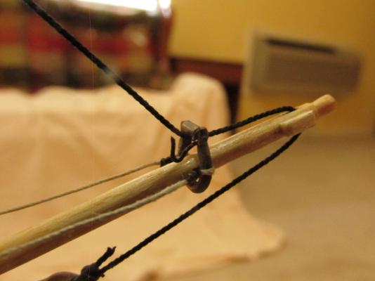
The Jib Stay was rigged once again with the new traveler this time with the hooked block and fiddle block (Syren Model Ship Co.).
- KenW, usedtosail and CaptainSteve
-
3
-
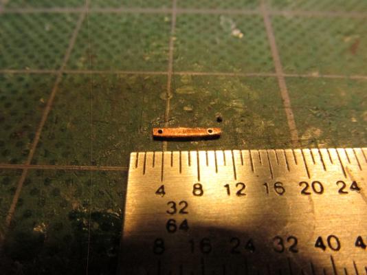
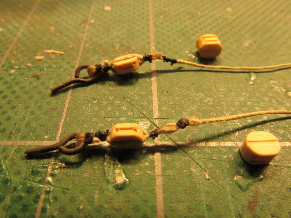
The excess rod was trimmed. I initially planned to epoxy the rod on the outside face because didn’t want to reheat the assembly and risk having everything fall apart. I didn’t have multiple solders of different melting points. But as it turned out, no glue was necessary as there was enough friction to hold everything in place. Comparing the two travelers, you can see my second attempt gave a much cleaner part.
- KenW, janos and CaptainSteve
-
3
-
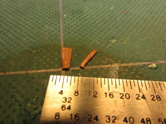
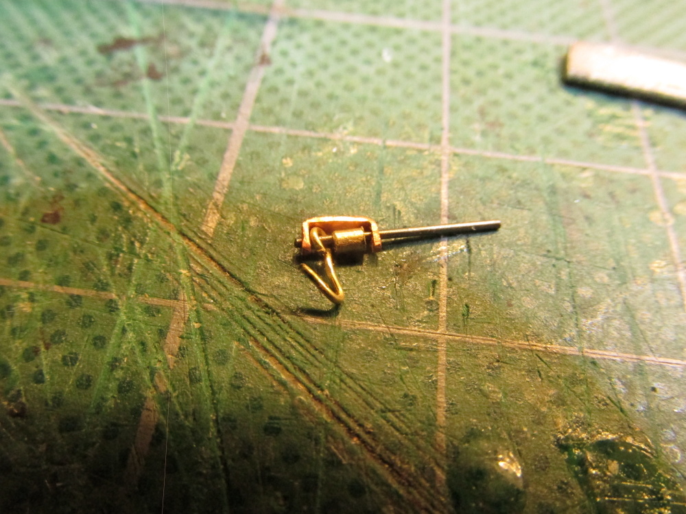
Another dry fit was performed and at this point I decided the roller needed to be a bit longer so another piece was cut. It ended up as 3mm long.
-
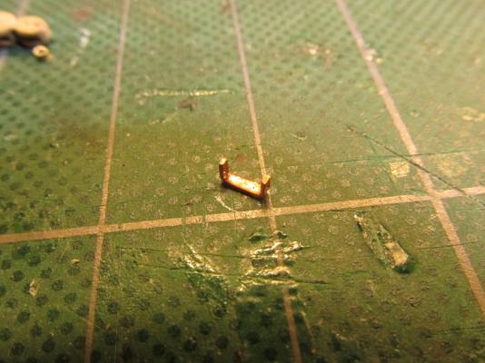
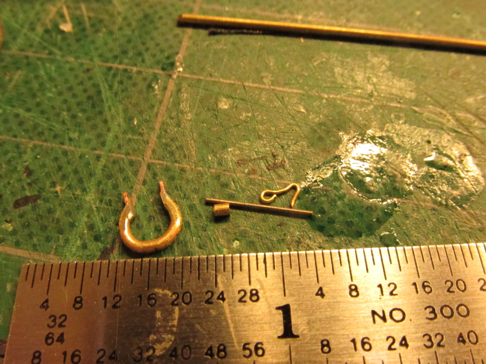
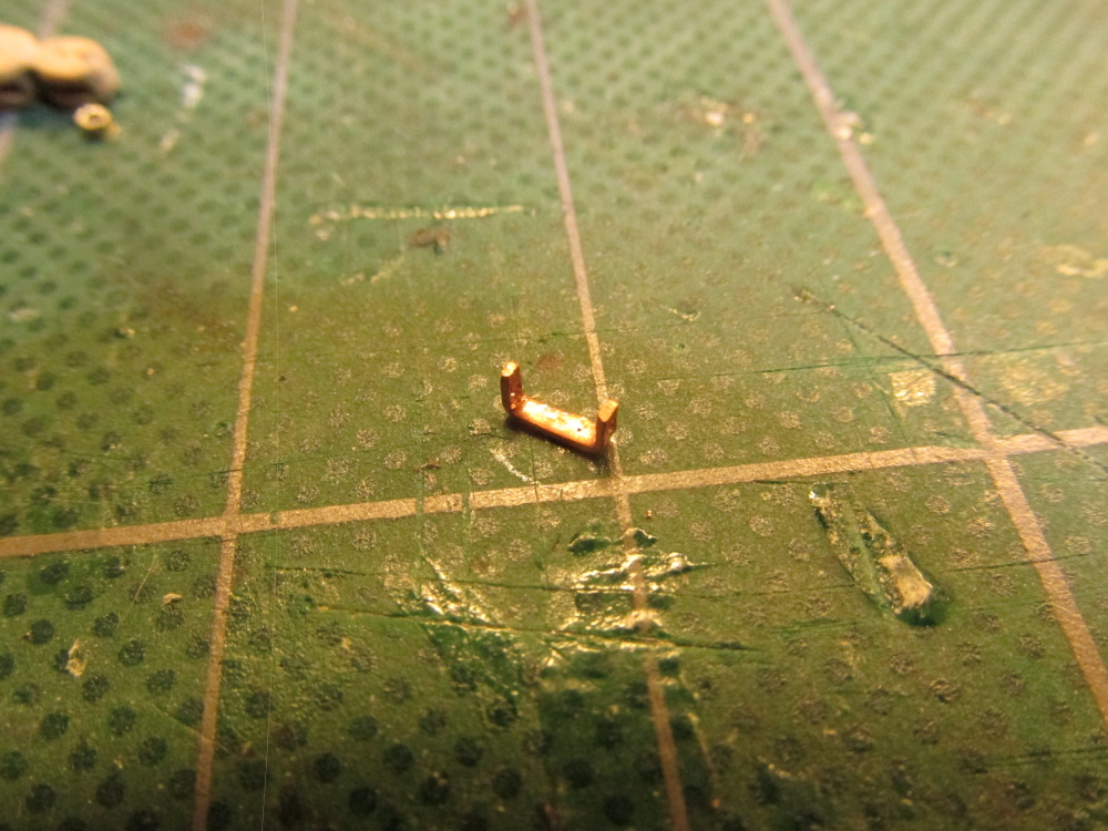
The U-shape served two purposes, first it obviously was part of the final structure but it also had a built-in second function – it held its shape so I didn’t have to fuss getting the vertical members with the holes lined up and soldered while keeping them in alignment. Having served its second purpose, the horizontal base was cut off and the excess solder was filed to shape.
-
A fine brush was used to apply the flux at the joints and tiny pieces of solder were placed in position. I didn’t want the solder to flow and plug the holes I drilled earlier. Another surprise, it worked!
-
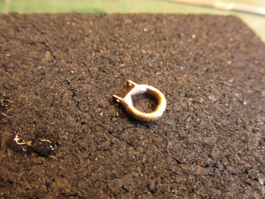
Now came the tricky part, I had to silver solder the U-shape to the ring. The ring was made like the first one but a gap was cut out and filed to fit the U-shape.

-
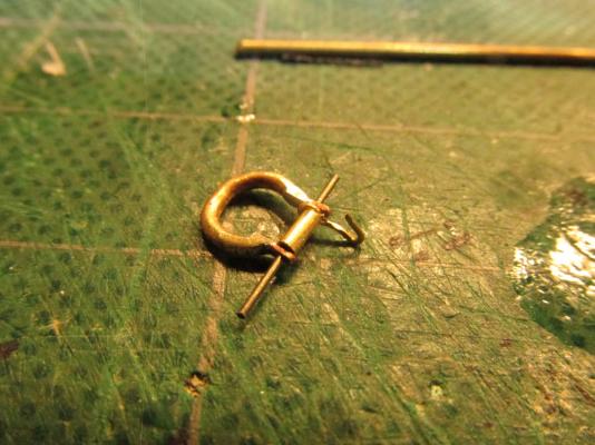
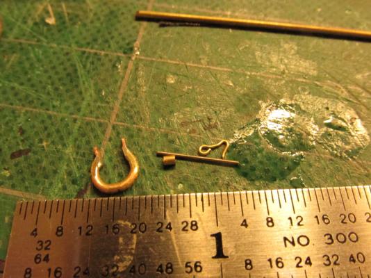
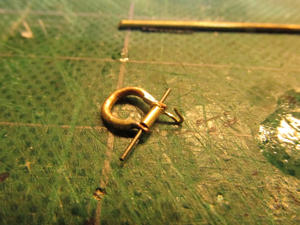
The hook, which had given me problems before was made from a 1mm (internal dia.) eyebolt using the tiny nails used for model railroads to wrap and shape the hook. My initial concern for strength went away because the eyebolt wire was stronger than my spool wire and the hook itself would not be put under any stress. The roller was simply a piece of 3/16” brass tube. A dry fitting was performed and surprisingly, everything fit.

-
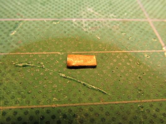
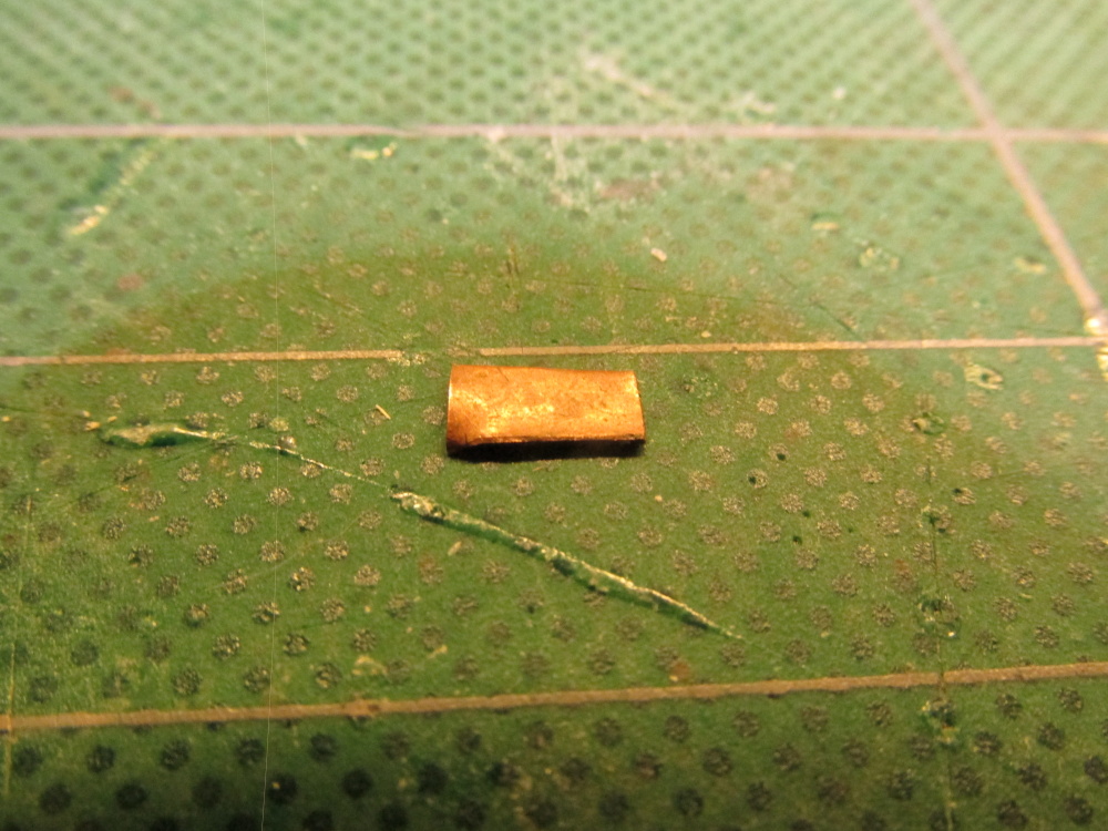
Starting off with a small piece of copper plate, a strip was cut off approximately 1mm x 9mm. Using a #76 drill holes were made at either end. Then the strip was bent into a 3.5mm wide U-shape so that the holes where about the same height from the base of the “U.” The top of the vertical members were filed rounded over.
-
Dave and Martin, well, I see you two liked that bit of rigging...but as it turned out I didn't.
The Jib Traveler - Redo
it was pointed out to me by a friend, that I installed the jib traveler backwards (the hook should be pointing aft) and upon further investigation reading Lees’ The Masting and Rigging of English Ships of War 1625 – 1860 and Lennarth Petersson’s Rigging Period Ship Models, it was realized (and in some cases contrary to the plans) that I also:
- Probably used the wrong style traveler
- Permanently attached the block that to the jib cap when it more than likely should have been hooked to the cap
- Use a double block that was part of the cap tackle when it more than likely a fiddle block
- Incorrectly (but per the Mamoli plan) tied off the tackle at the jib cap which made no sense to me. The tie-off from the cap actually goes to a forecastle railing stanchion cleat per MS plans and inferred by other references.
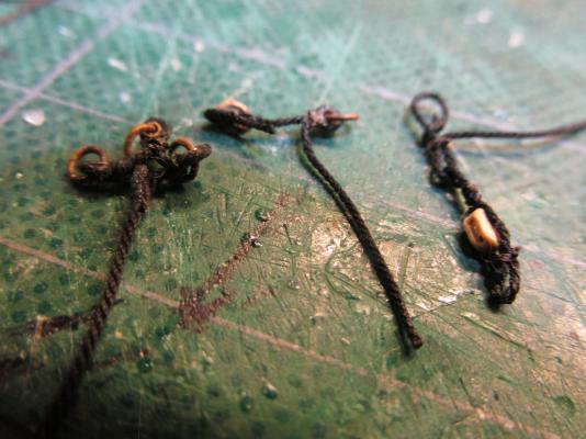
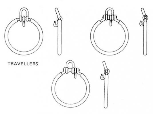
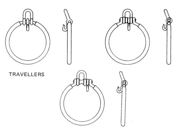
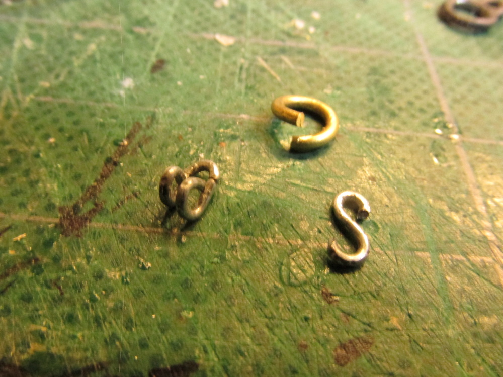
First off the traveler had to be changed. The U-shaped hoop had to go and be replaced by a roller. The MS plans do show the jib traveler with a roller. I elected to use the roller traveler with hook shown in Lees’ but without the hoop. Second, I thought about modifying the existing traveler I made but because I didn’t like the traveler’s hook (too large), I decided to start fresh from square one. The below images show the travelers from Lees book, Model Shipways, and final my modified version.
-
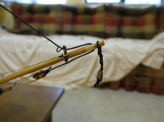
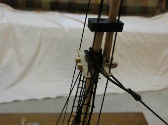
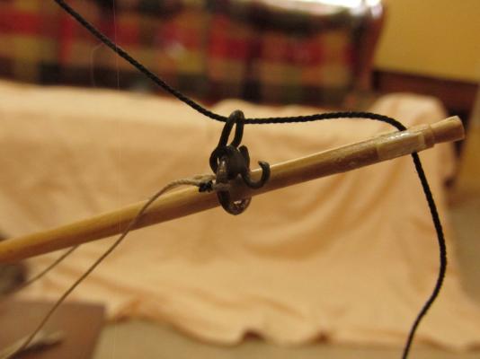
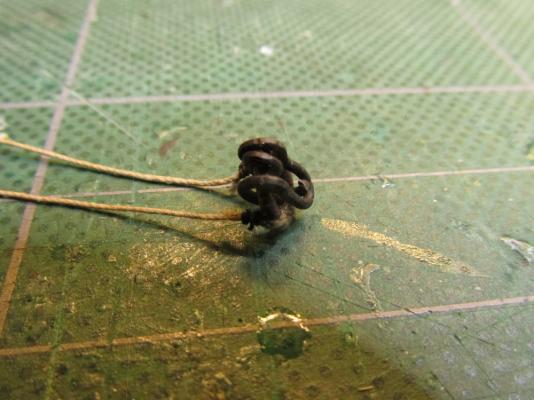
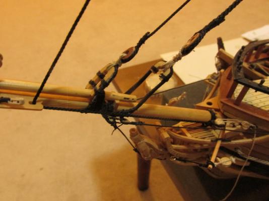
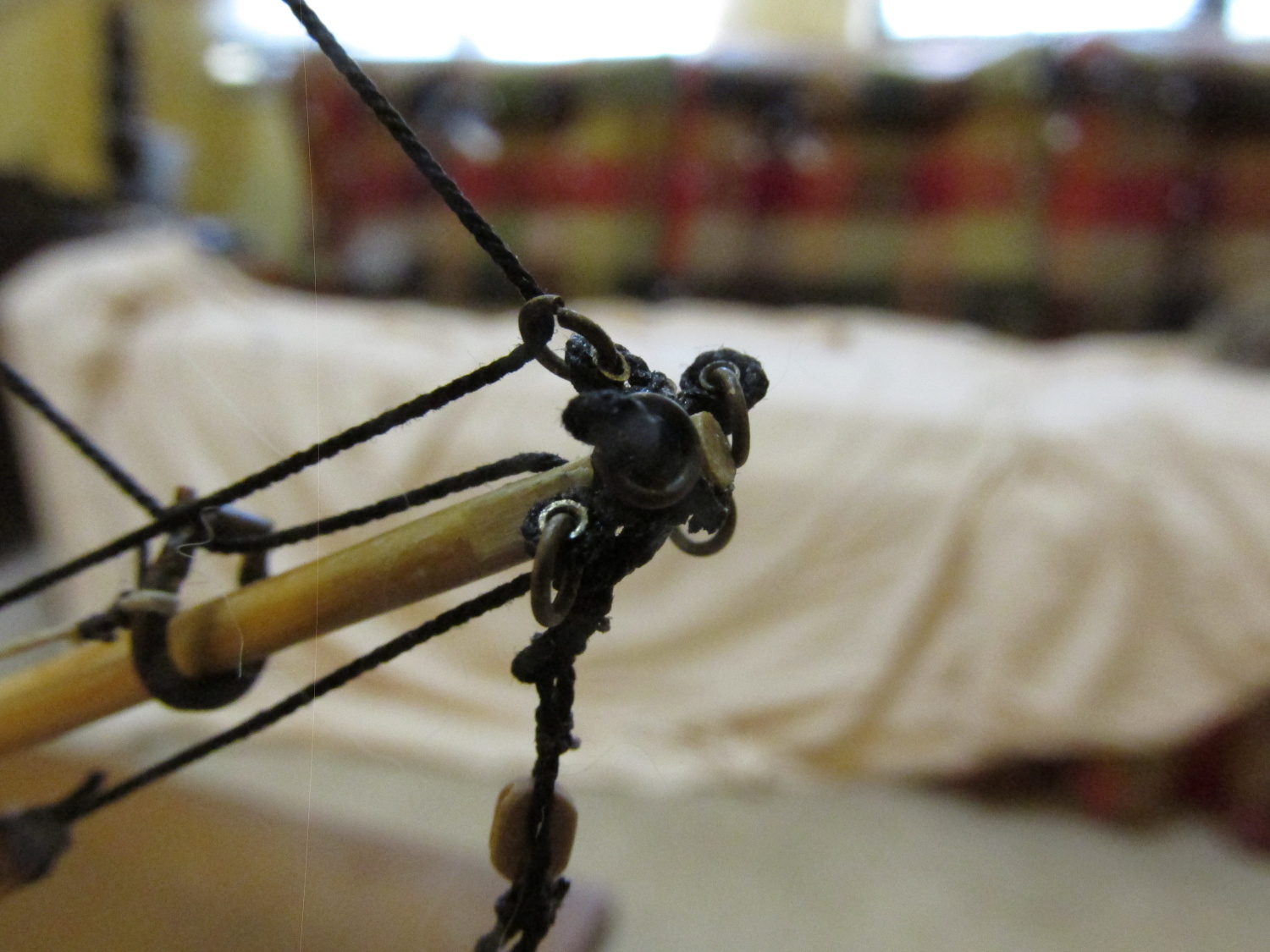
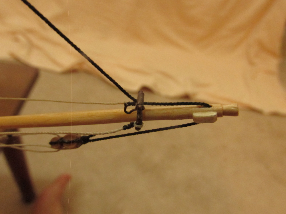
The Jib Stay is looped over the Fore topmast using a mouse and passes through the jib traveler and into the jib sheave where it terminates at a double block. The tackle is constructed the same way as the termination tackle of the Fore Topmast Stay and Preventer Stay. In the last image, it’s hard to see, the jib traveler lines terminate at the belay pin rail. In this case the tie off at the pin is temporary and will be finalized later.

-
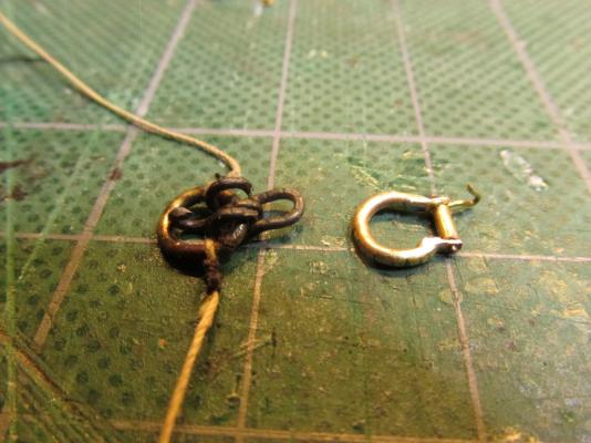
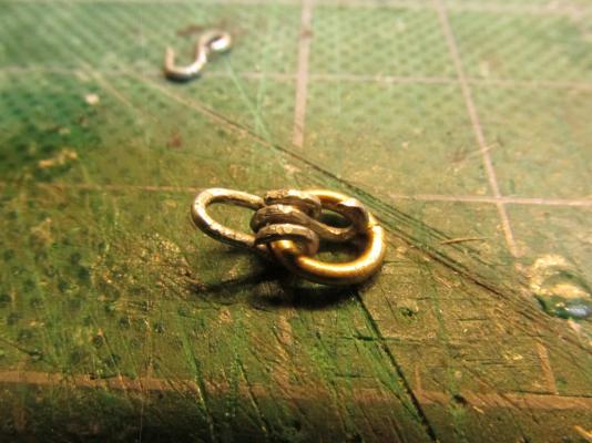
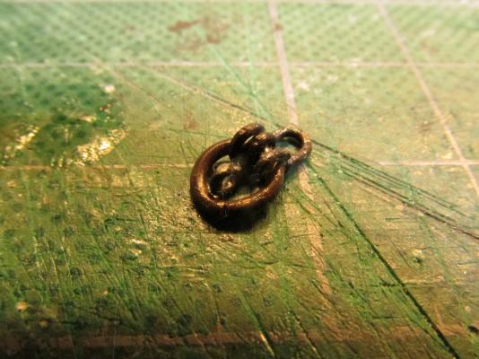
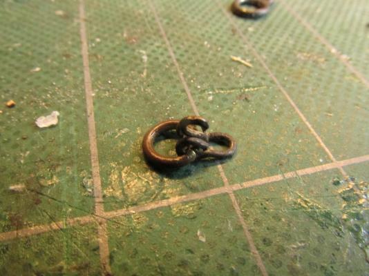
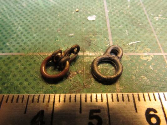
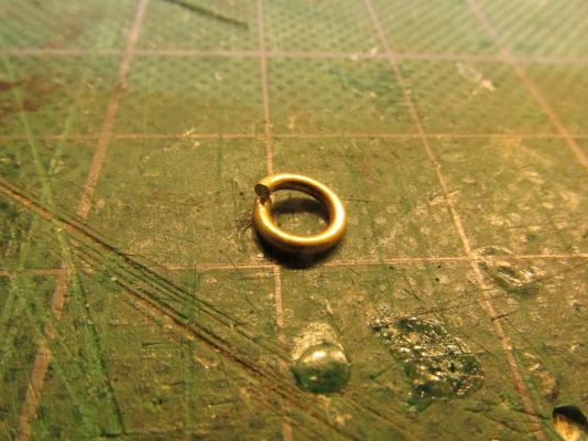
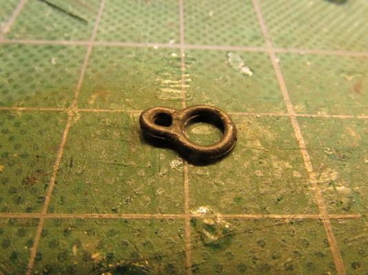
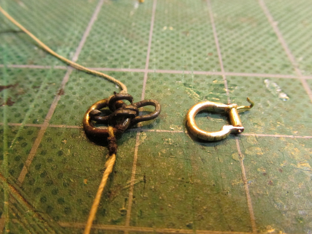
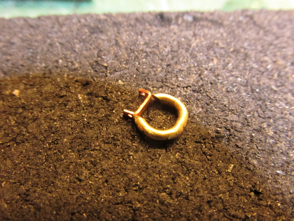
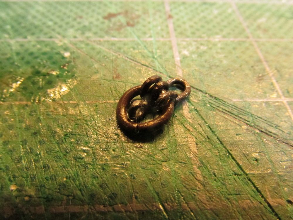
Once the pieces were made, they were assembled and the main ring was closed. It was at this point that I gave the assembly an acid bath and then blackened it. I figured there would be less chance of scrapping the blackened surface afterwards than before. The final touch was to paint most of the ring outside the shackle area brown to simulate leather. The rings were normally covered in leather to protect the jib from wear. It’s kind of difficult to see the brown color against the blackened metal so I guess I could have skipped that step. The next to last image compares the kit traveler and my version. The final image shows the lines used to pull the jib traveler towards the bow attached.
- CaptainSteve, Martin W and KenW
-
3
-
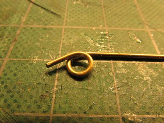
I wanted to make the shackle from thinner stock but as I stated I didn’t have any suitable brass rod, so I improvised and used a paper clip. I did not want to use too fine of wire because it would not have any strength. Because I did have suitable diameter music wire I had a fleeting thought of using that, but dismissed that idea as impractical as it would be too tough to bend to the required tight curves with the tools that I had. As pliable as paperclips are, at this scale, making tight loops was still tricky. I used a pair of closely nailed brads in a piece of wood to wrap the ends around to make the tight loops. Along with other instruments of mass destruction (hammers, needle nose pliers, etc.), the shackle was made…twice. The first one broke due to over manipulation of the metal – metal fatigue. The little hook was a problem. I just could have made it at the size shown with thinner wire but it would have bent too easily at the barest touch so I had to make it bigger.

- KenW, Martin W and CaptainSteve
-
3
-
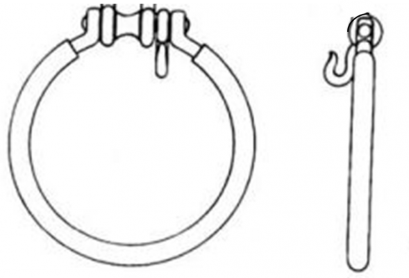
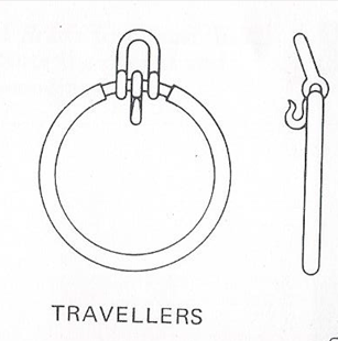
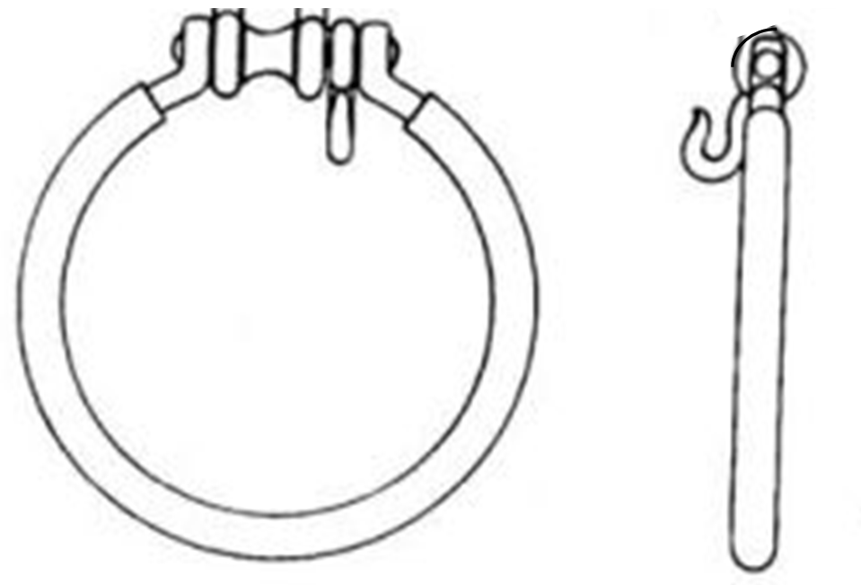
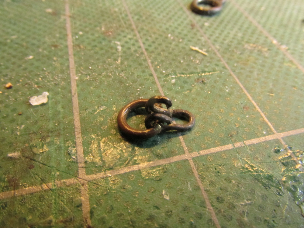
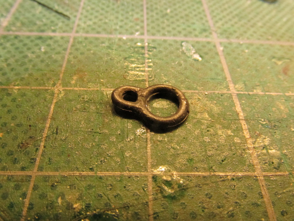
As you can see, the real thing is a bit more complex than what was provided in the kit. For one, the little loop atop the ring is a moveable shackle and two, there is a little hook which according to Antscherl, is for the “jib sail tack cringle… [which] is a loop of rope formed at the lower forward corner of this sail”). Because my model won’t have sails, the hook will go unused.
As an aside, I don’t know what hardware Model Shipways provided in their kit, but their plans show a roller in lieu of the shackle and no hook. Lees does show that variation in his book.
To start, I used a 3/64” brass rod to make the initial ring. I wanted to use a 1/32” rod like Antscherl, but did not have one. The difference was within the tolerances provided in Lees’ book.
-
Having jumped in with both feet in fabricating most of the other components, I decided to give this a crack. I was in luck that both David Antscherl and James Lees agreed as to what it should look like. This illustration is from James Lees’ The Masting and Rigging of English Ships of War 1625-1860.
-
Jib Traveler
The Mamoli kit provided a Jib Traveler. It is a ring component that fits over the Jib Boom and receives the Outer Foremast Stay from the Foremast Top Tree and directs it to a sheave at the tip of the Jib where it ends at the bowsprit cap. It is designed to slide along the Jib Boom adjusting the stay.
-
The Fore Topmast Backstay was constructed just like the Mizzen Topmast; the ends terminating to a pair of lashed rings coming off the aft deadeye.
The Fore Topmast Stay and Preventer Stay each looped around the topmast tree requiring a mouse and passed through the bees – the Stay through the forward opening on the Starboard side and the Preventer through the aft on the Port. From there they terminated at the bow using a pair of single and double blocks. Because the lines pass through the bees, the double block had to be attached to the rope on the model. The other half of the rigging, the single block, the rope, and eye ring were assembled off the model.


- CaptainSteve, GuntherMT, DocBlake and 3 others
-
6
-
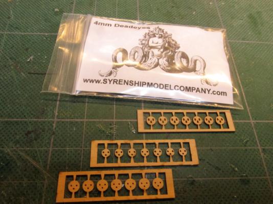
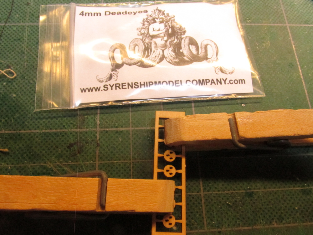
The Main Topmast Backstay was constructed the same as the Mizzen Backstay except instead of rings, deadeyes were required. The lower deadeyes were previously installed but unfortunately, the kit came up short by at least two for the backstays. Using the laser cut deadeye kit supplied by Syren Model Ship Company I then preceded to make-up the shortfall.
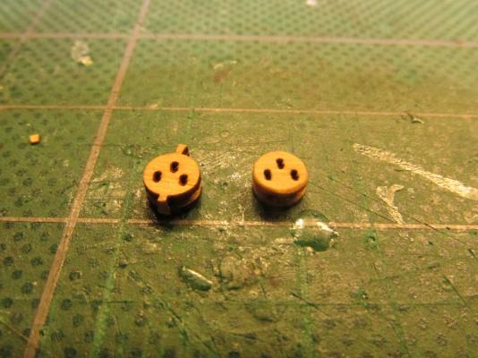
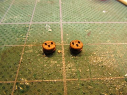
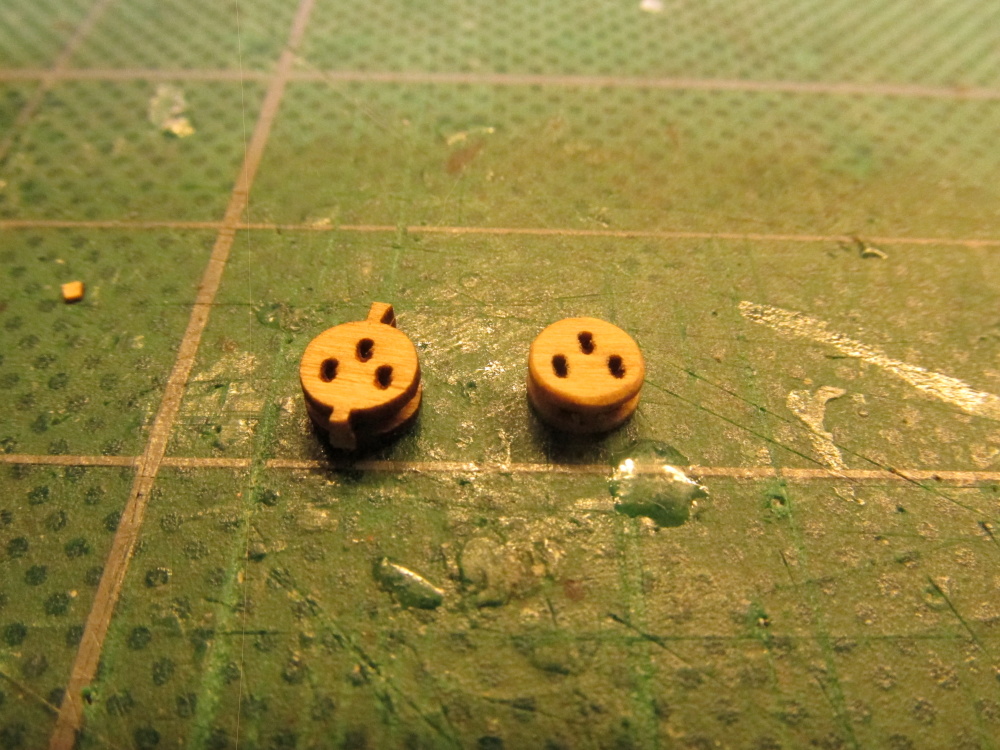
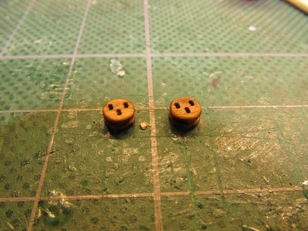
The deadeye kit consisted of two identical side framed layers and a centerpiece layer containing multiple deadeyes; in this case seven. They are to be assembled as a group. Making sure the outside layer had their outside faces facing outwards and the holes were all facing the same direction, the three layers were glued together with CA as directed. A few minutes later, I cut off two deadeyes. The downloaded instructions strongly suggested using a block tumbler but since I didn’t have one and at this stage only needed two deadeyes (so far), they were hand filed and sanded. The holes, which lined up very nicely, were drilled to remove any excess glue and then stained.


Rattlesnake by JSGerson - FINISHED - Mamoli - 1:64 - Using Robert Hunt’s practicum
in - Kit build logs for subjects built from 1751 - 1800
Posted
Using a piece of 1/64” square boxwood stock, two staves to act as stretchers were formed each with holes to allow the horses to pass through. Once the holes were drilled, the square staves were rounded into rods.