


JSGerson
-
Posts
2,652 -
Joined
-
Last visited
Content Type
Profiles
Forums
Gallery
Events
Posts posted by JSGerson
-
-
I'm overwhelmed! Thank-you all.
Jon
- Blue Pilot and Martin W
-
 2
2
-
Gregory - I wasn't kidding about not having a woodworking background. When I started the Rattlesnake I owned some screwdrivers, a hammer, some wrenches, you know, your typical household repair stuff. I did not own a saw. When I started to buy tools, they were all for the model making. So I now have a Brynes saw, a Brynes thickness sander, a 35 yr old Dremel scroll saw, and rotary drills with a drill press accessory. Any wood working stuff I have is all for model making. I still don't own any full size wood working tools. 8-)
Jon
-
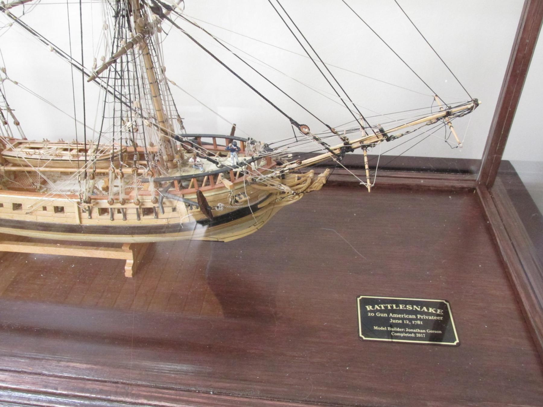
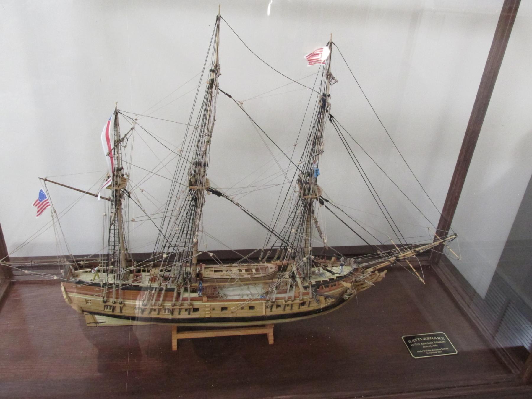
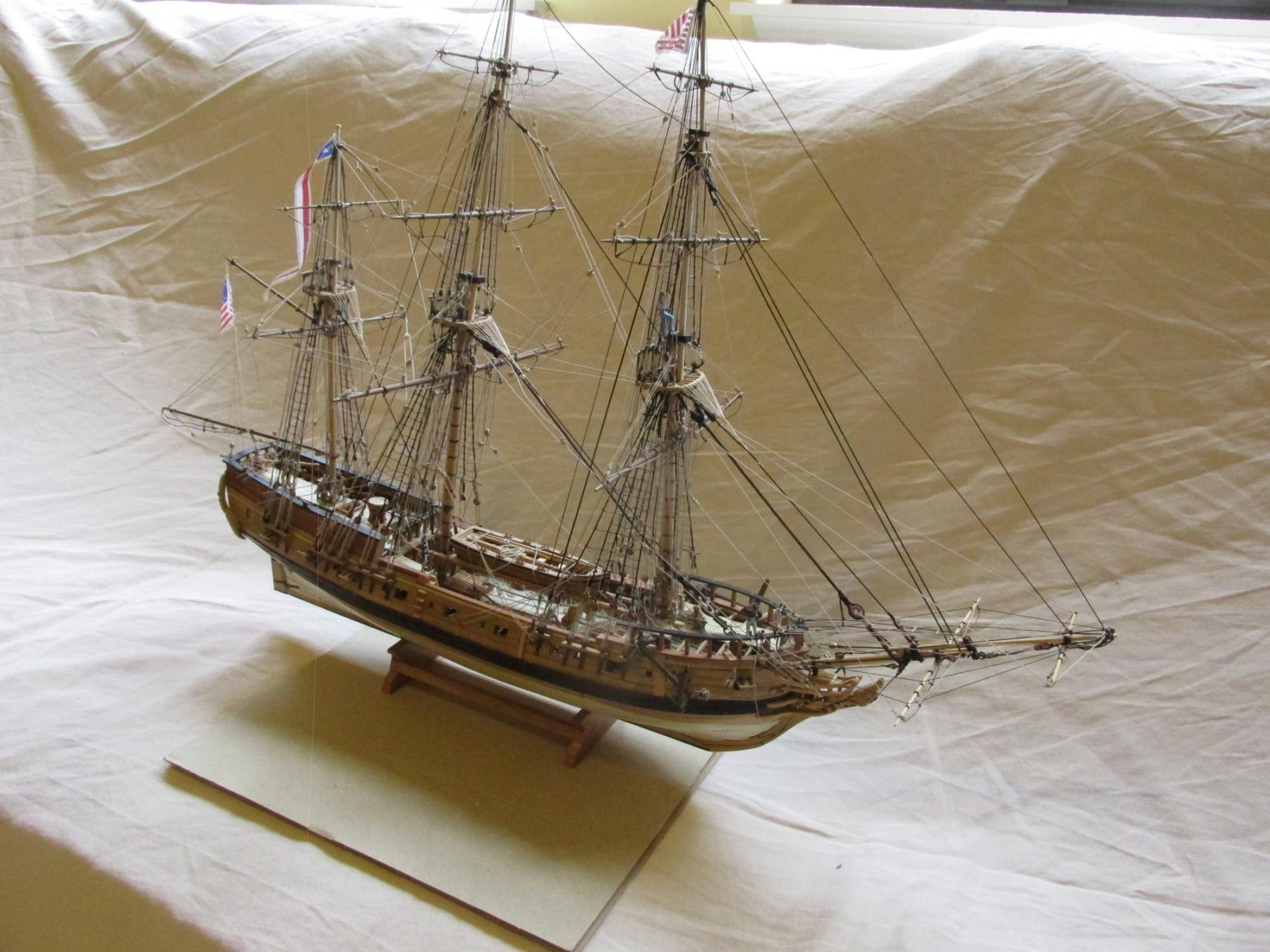
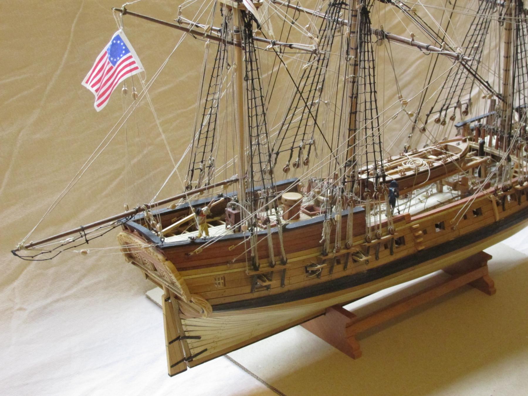
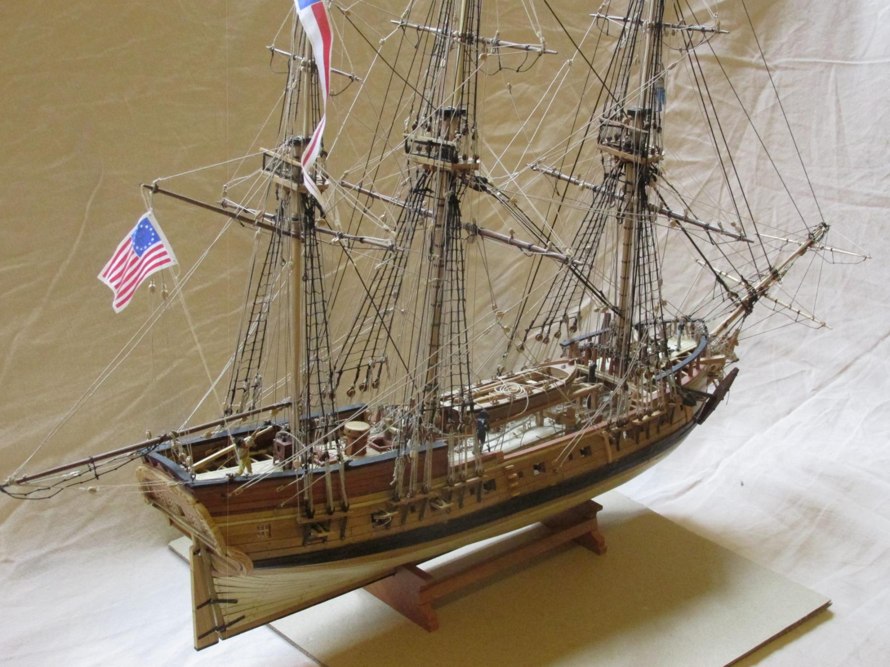
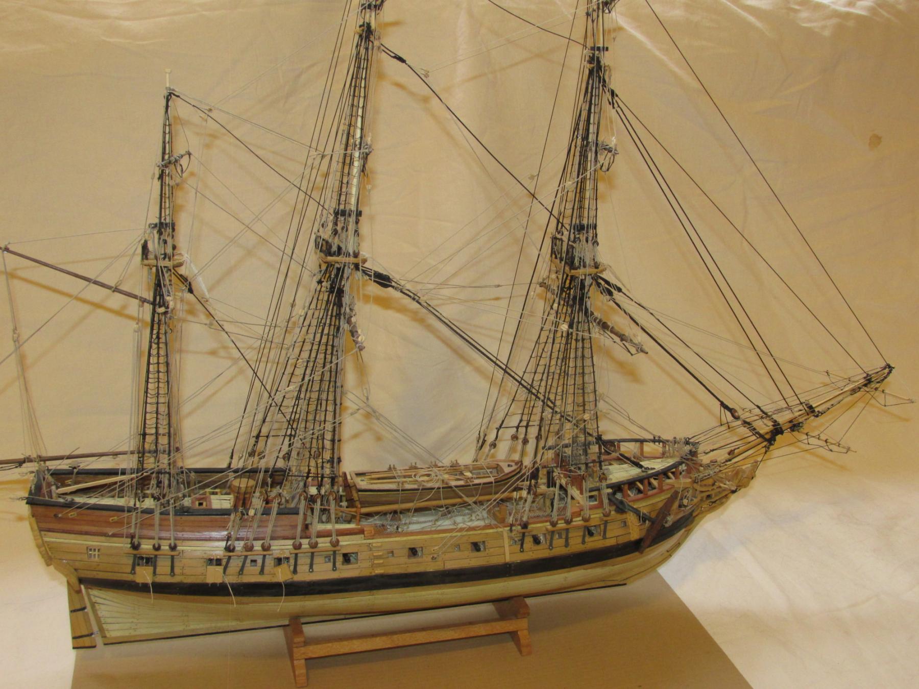
FINISHED
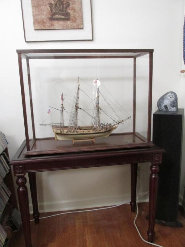
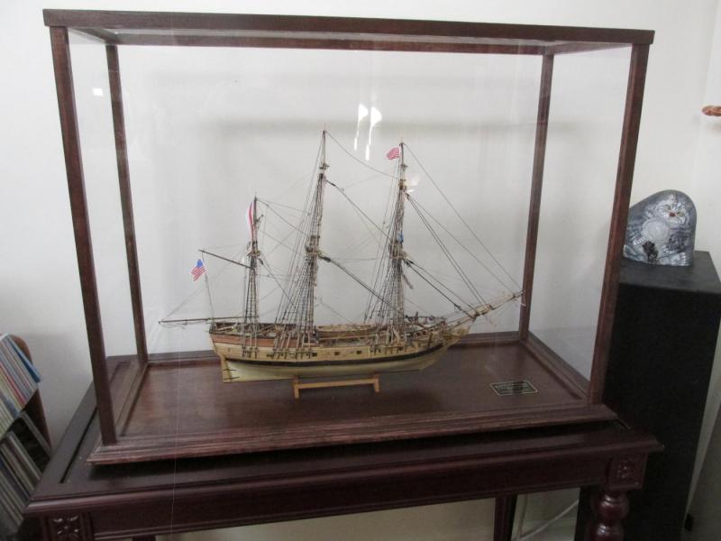
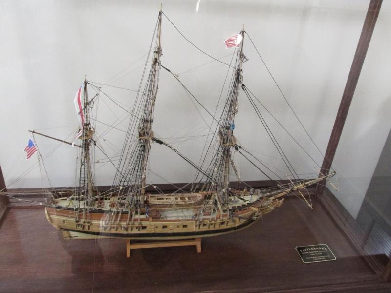
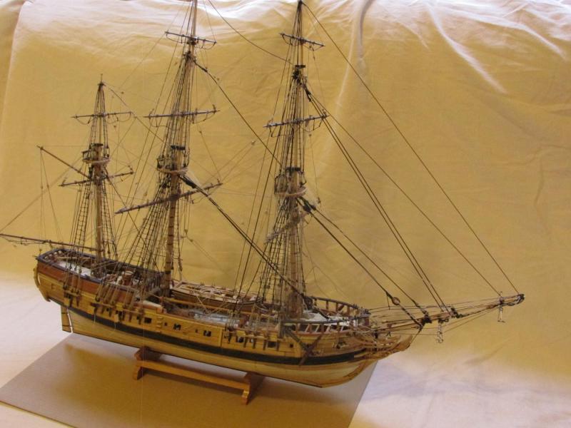
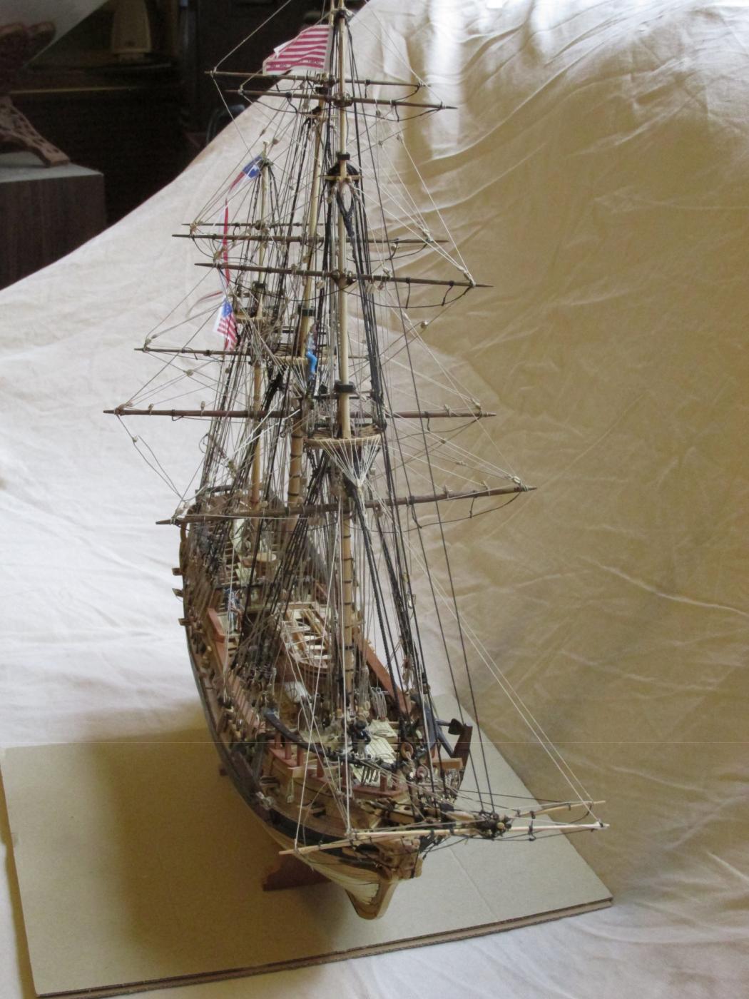
Well here they are, the last planned official images of my Rattlesnake, safe and snug in her case. For those who followed my loooonnnnnng and s l o w build over the past seven years, once again, thank you for being so patient and thank you for all the “likes.”
-
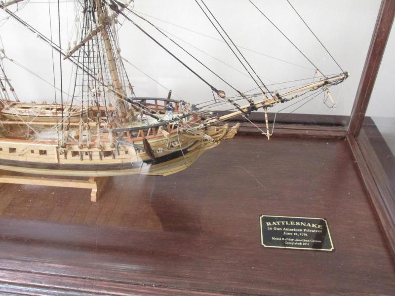
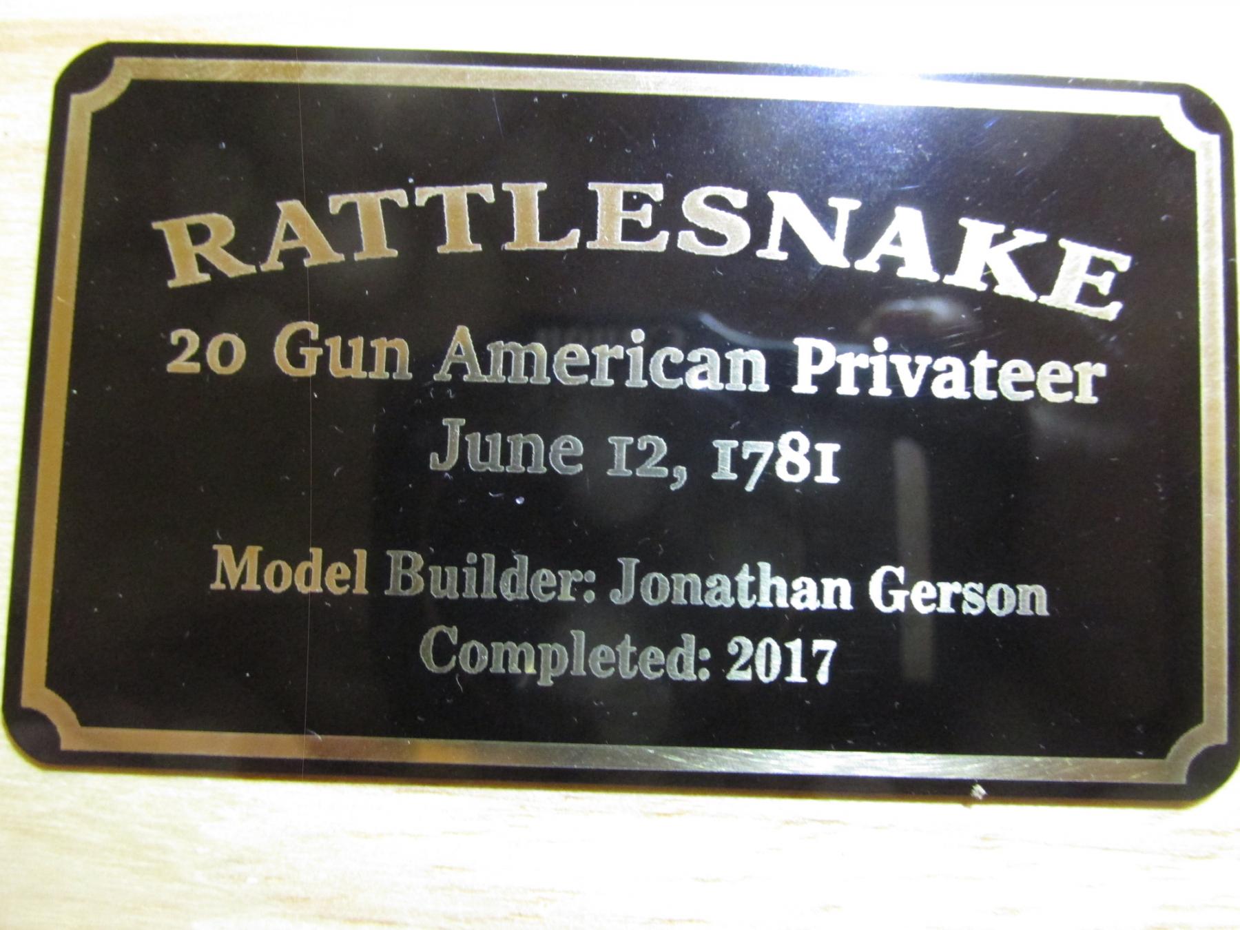
Name Plate
I had a name plate made from a local trophy shop. I gave them a mock-up I created in Powerpoint, and they reproduced it beautifully.

- KenW, Jack12477, CaptainSteve and 3 others
-
6
-
KenW - I got the 1/8" plexiglass at my local glass shop (auto and other repair). I initially tried Lowe's but they were all out. The I went up the street to Home Depot (they always seen to come in pairs, don't know why) and they did have it but they would not custom cut it like Lowe's would have. The third try was a charm; the glass shop had it and custom cut for me. They even re-cut it again (no charge) when I realized my dimensions were a little off and it needed a minor trim. I had to get 1/8" thickness because that is what the case required. Once the wooden frame was around the plastic, the panels were very sturdy.
The case (No. GM7W) I got from Model Expo as I mentioned in post #949 above
Hope this helps
To all - Thank very much for your "likes" and following me on this long slow journey. Once I've buttoned up the model in the display, configured and customized my new computer, and taken a small breather, stay tuned and I will start the next journey on the USS Constitution
Jon
-
-
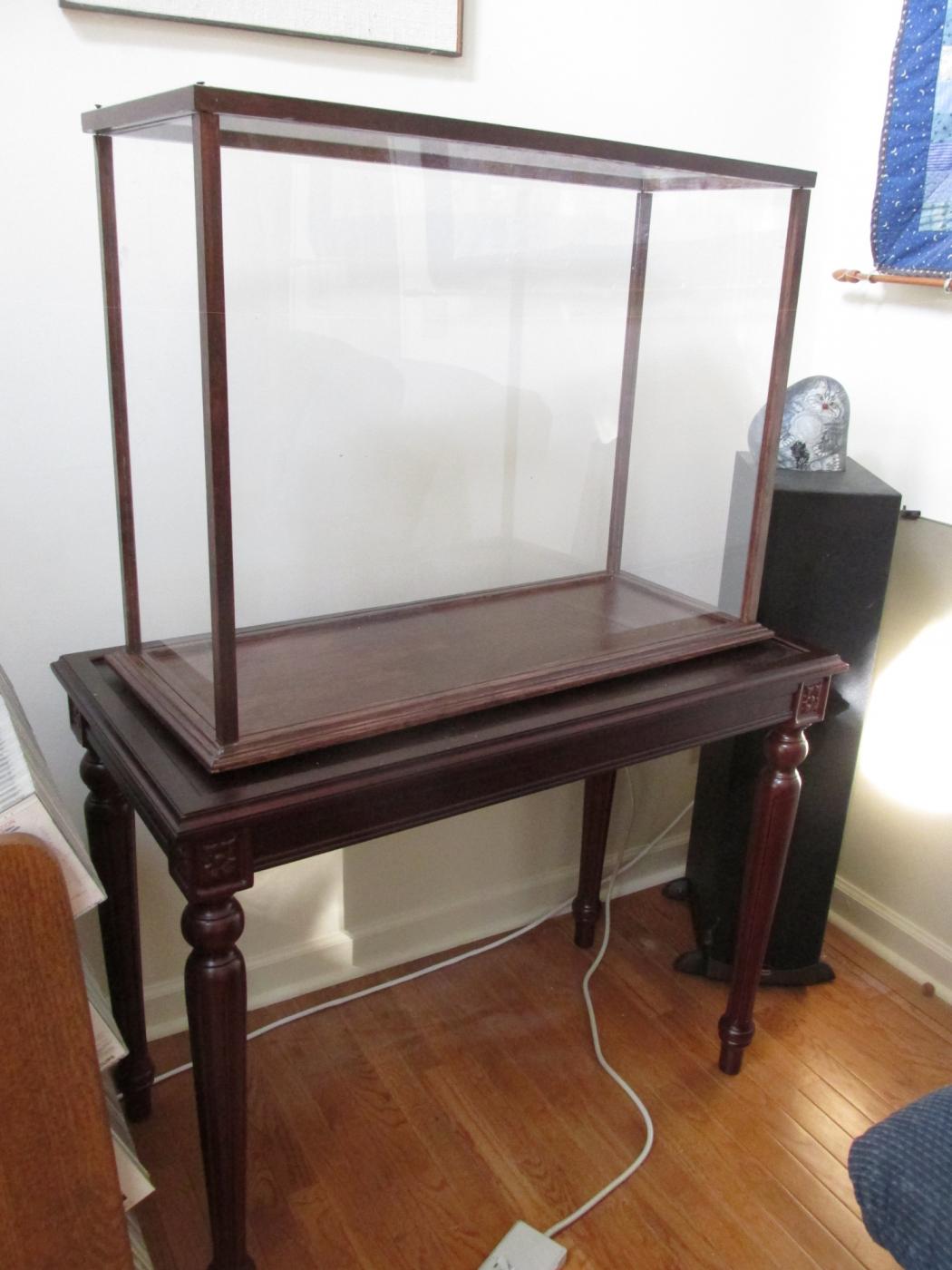
The height of the case can be shortened by slicing off the appropriate amount from the vertical frames. I cut 4” off. The frames have a 1/8” square groove on two adjacent sides for glass or in my case plexiglass. I didn’t relish the thought that the case could conceivable break and the glass shards do irretrievable damage.
The only real problem I had was that the case assembly instructions stated that the vertical posts needed to be predrilled to accept the wood screws so that the post would not split. I made the mistake of assuming that the drilled holes were to be dead center of the cross section of the posts; it was not. I should have marked the drill point from the predrilled hole in the top frame the post connected to. So the holes did not line up properly and I will have to fill with plastic wood and re-drill. I have no woodworking background, so live and learn.

- Nirvana, CaptainSteve, Martin W and 3 others
-
6
-
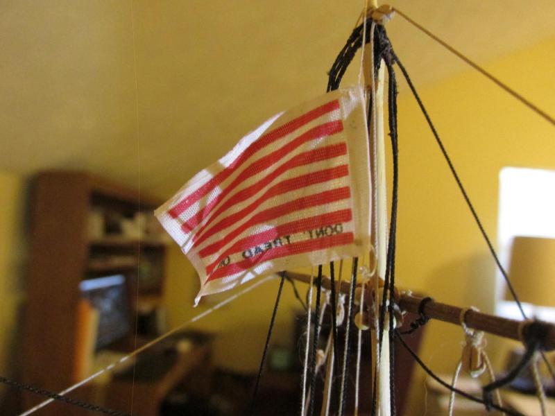
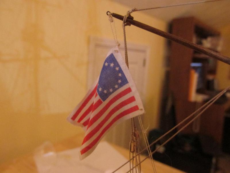
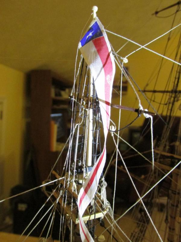
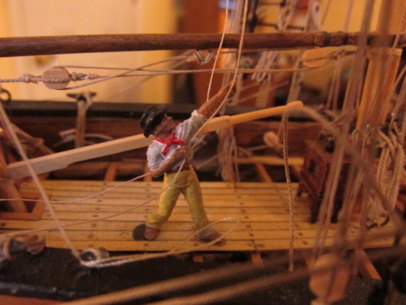
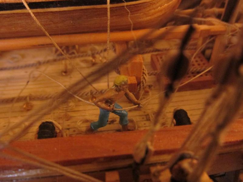
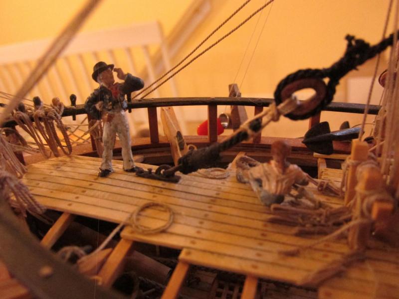
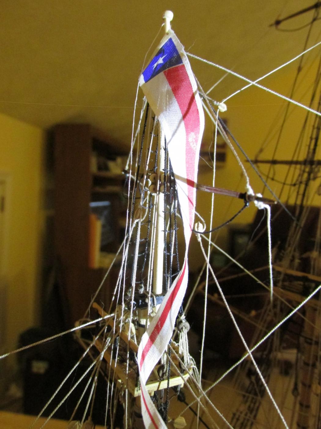
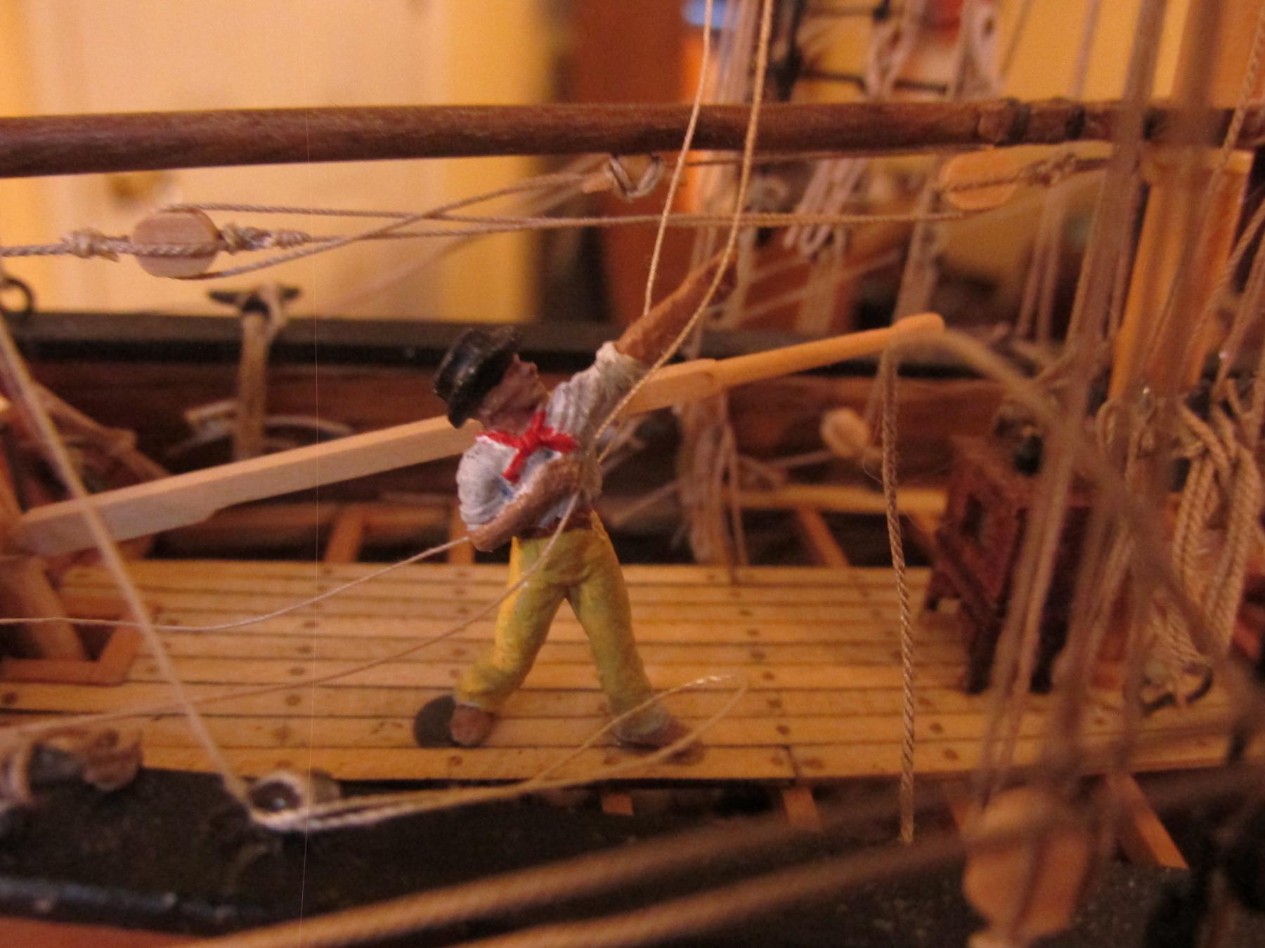
The flag on the Mizzenmast is not belayed on the model as it is being “hauled” by a sailor figure. The Foremast flag is belayed to the bitt rail.
That’s it. The model is complete and it only took me 7 years!
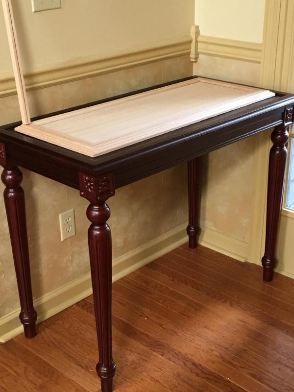
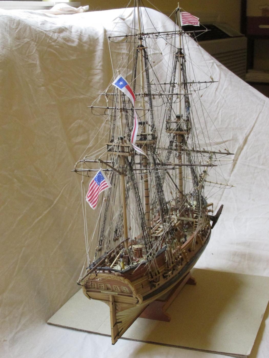
Display Case
I also worked on the display case and table. I purchased a Rosewood table from HandcraftedModelShips.com and case I got from Model Expo three years ago during a sale. They don’t make the cases but contract out to White's Woodworking in Osceola IA. The case was made from Red Oak without any finish which meant I could/had to stain it the obvious color, Rosewood. I couldn’t find any Rosewood stain locally and had to order it on the web. It took three coats to get it as dark as the table. The shade is close enough although not perfect, but it will have to do. The first picture shows the table in a temporary location with the base board and one case frame pillar before any stain
- JerseyCity Frankie, Jack12477, KenW and 4 others
-
7
-
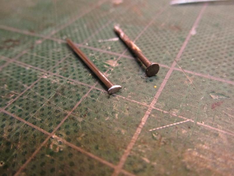
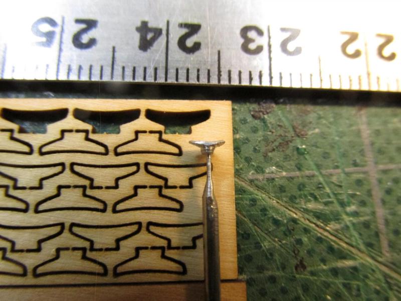
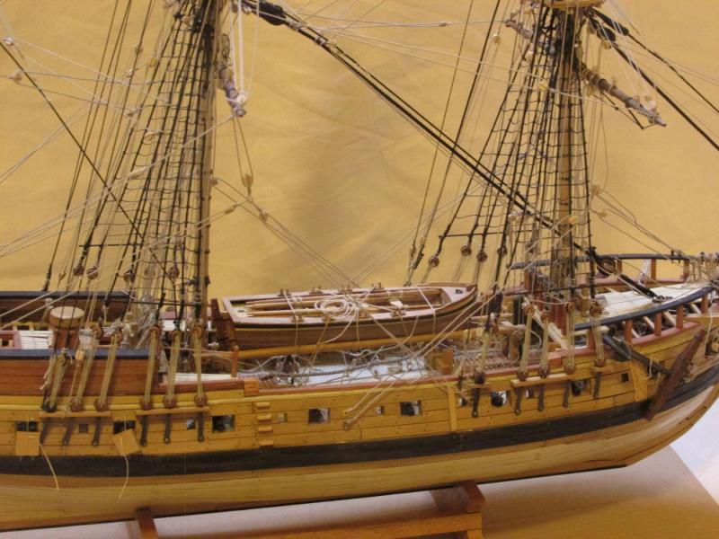
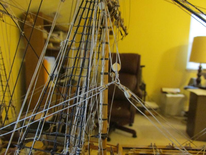
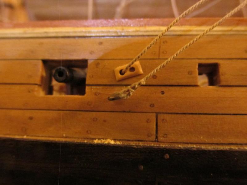
Gaff Flag Cleat
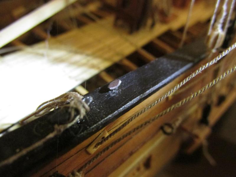
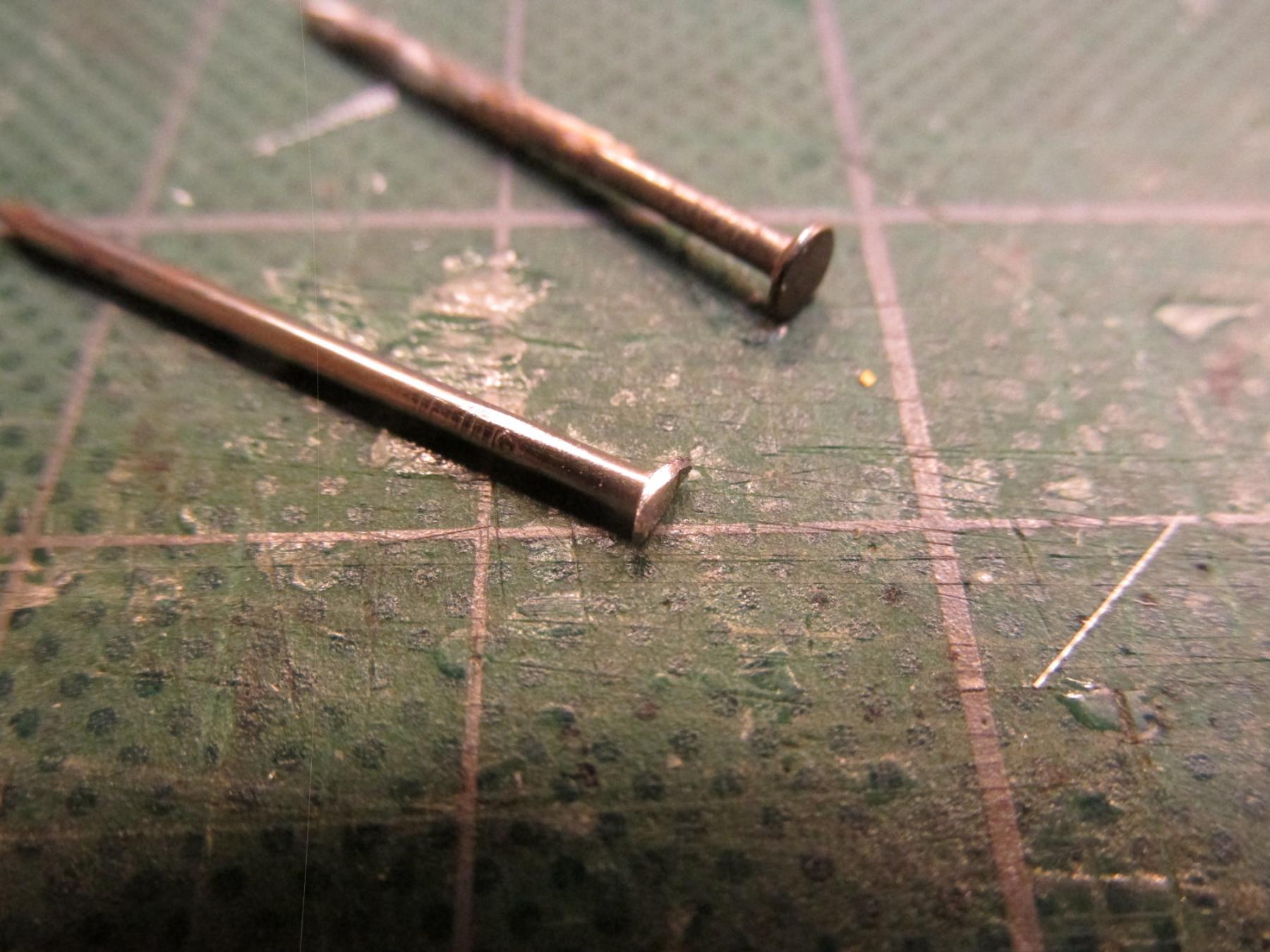
Then there was the old question I posed some time back when I was rigging the gaff. Where does the Gaff flag halyard belay? My initial though was to a cleat on the boom and as it turns out, the Mamoli plans show just that. However, at the last NRG convention in San Diego, a two-masted schooner ride was offered to the members which I partook. I noticed that when the sails were lowered, they covered the booms and any cleat that would have been there would have been buried under hundreds of pounds of sail canvas. Also, my research indicated that flag halyards are belayed at any convenient point on the deck. So, I decided to add a cleat to the aft railing.
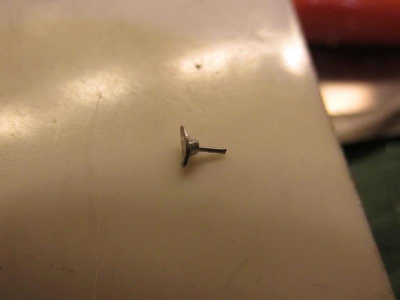
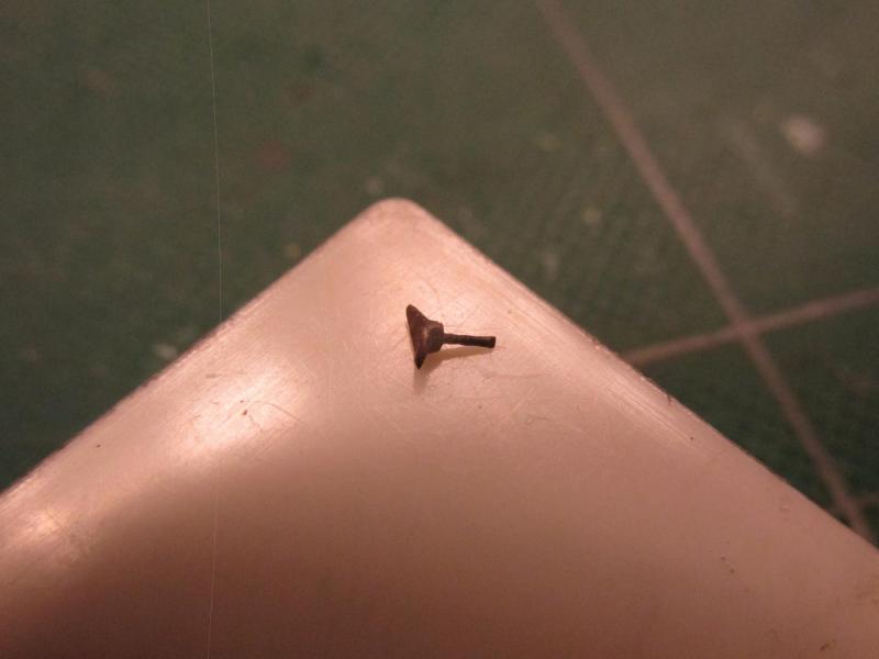
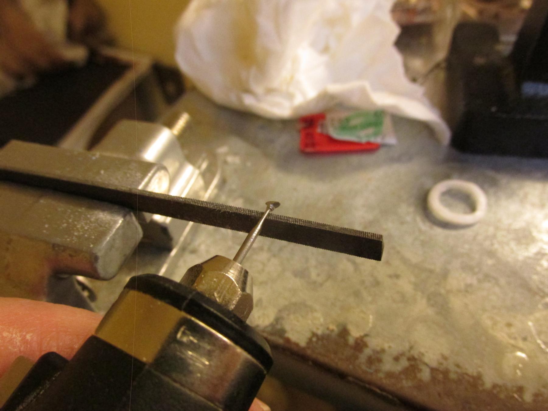
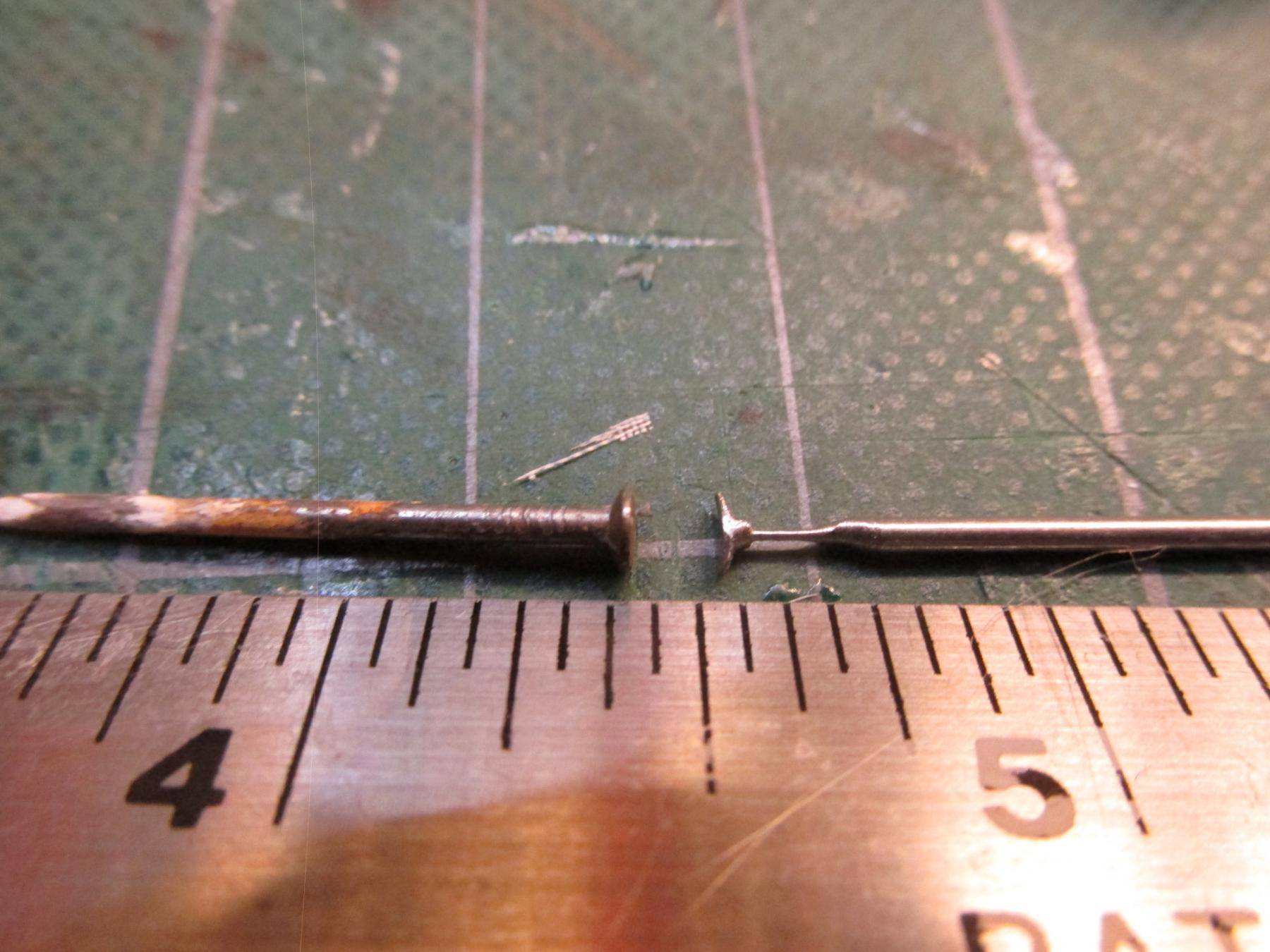
Flag halyards are probably the smallest diameter rope used on the ship and I figured that any of the cleats I had were too big including Syren’s 5mm. Using a technique I developed when I was building the Mini-Mamoli solid hull schooner Evergreen, I made a 2mm metal cleat. Using a nail intended for a picture hook, I filed off the opposites of the nail head. By shaping with the file the remailing head and bending them slightly upwards, these would become the horns of the cleat. I also filed the shaft just under the horns to make the nail shaft a bit oval. This was the cleat. I needed a way to fasten the cleat to the rail so I formed a pin by putting the nail into a Dremel drill and very gently ground the shaft to the thickness of a #75 drill bit (0.021”) using the edge of a small file. The cleat was cut off the shaft and then blackened.
I wanted to place the cleat on the inside edge of the rail, but at this stage of the build, there was no way I could do that. It was placed on top. I documented the rudiments of this technique (excluding the pin) some time back on The Kit-Basher's Guide To The Galaxy blog.


-
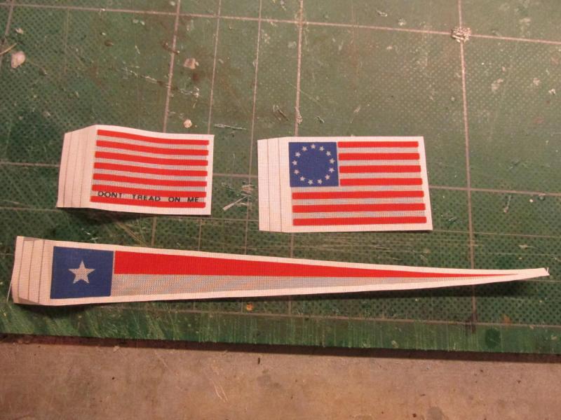
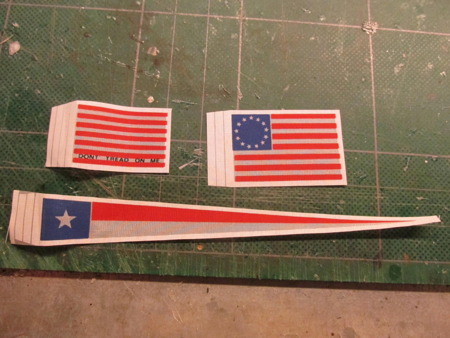
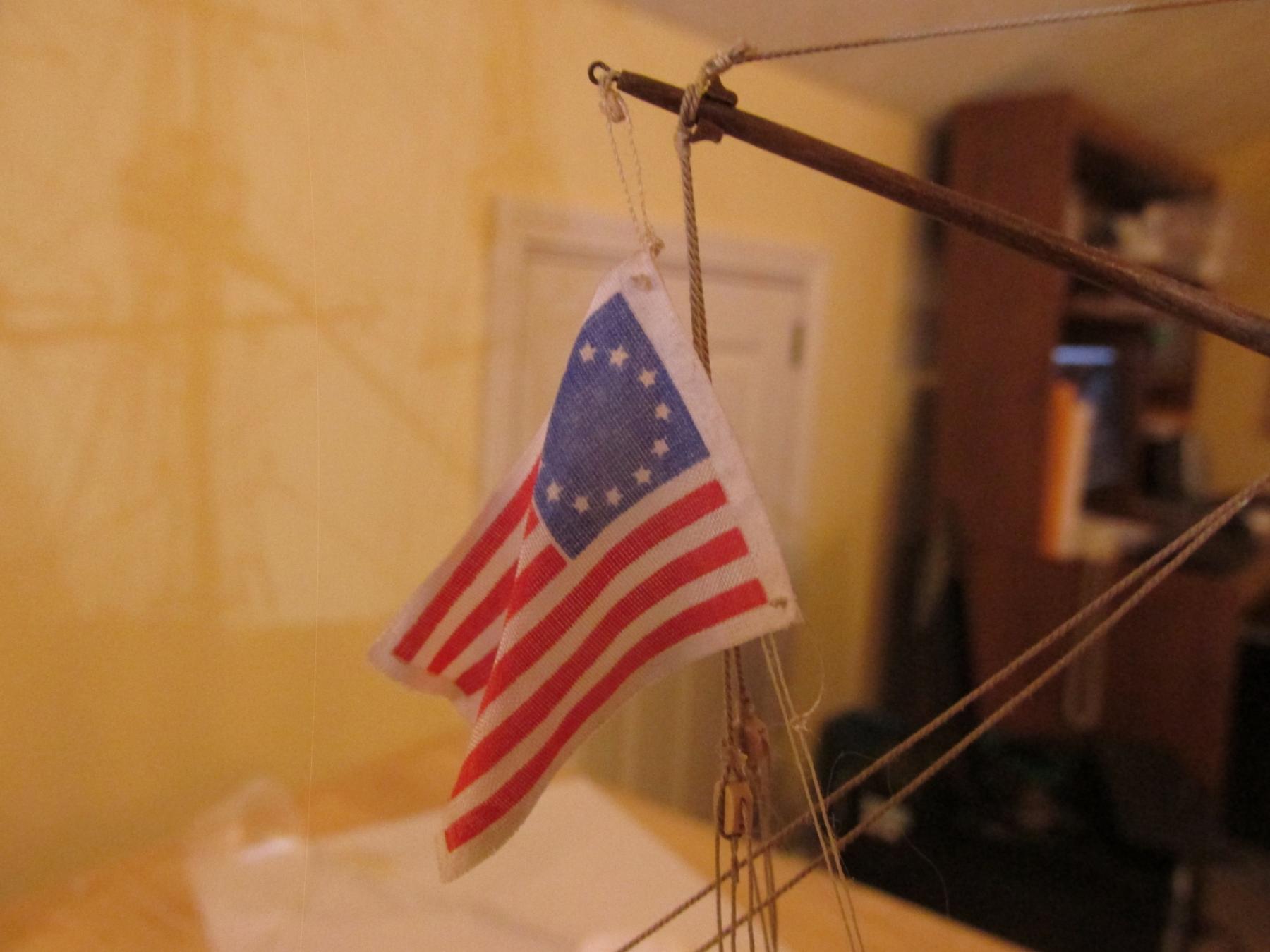
Flags
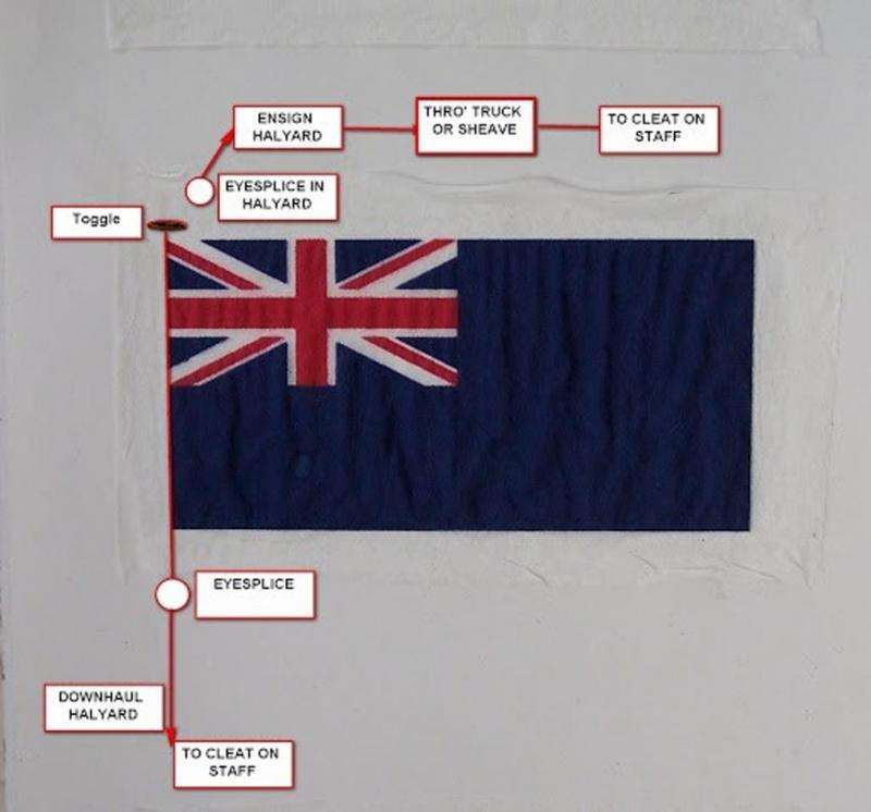
The kit flags were made of a stiff material and should hold their shape. I soaked them for a few minutes and they softened up a bit and added the wind contours. The kit instructed me to fold the side border material over the halyard line to fasten flag. I didn’t do that. After a bit of research I came upon a number of posts on this site which showed a flag diagram originally posted by Blue Ensign explaining how a flag is attached to the halyard. I followed his lead.
- davec, Charlie, mort stoll and 4 others
-
7
-
It’s been a while since my last post and believe it or not, some things were accomplished. I think I have belayed the remaining lines (you never know where a loose one may be), and repaired the anchor tie down and the gunport doors.
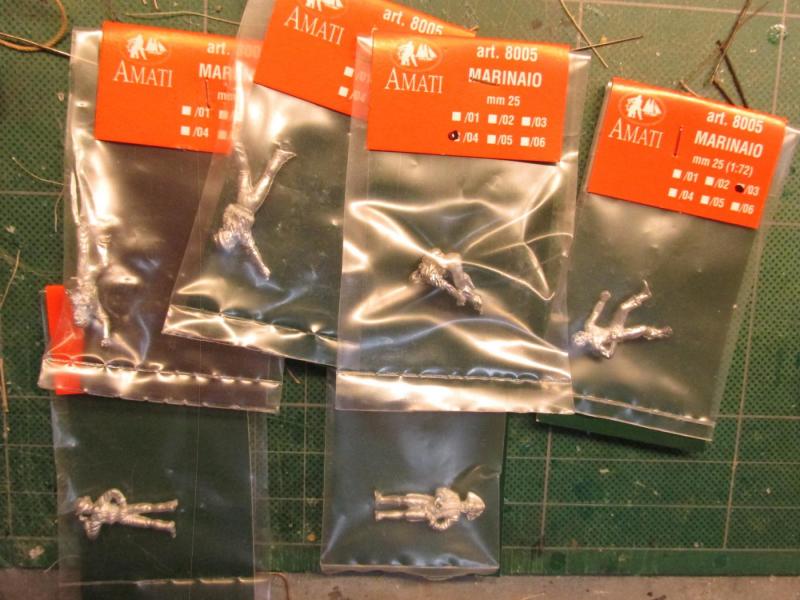
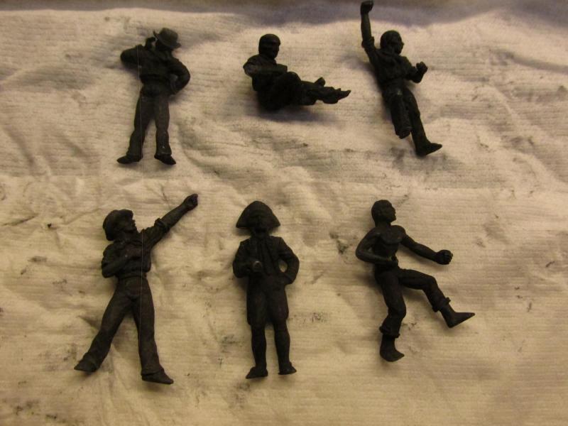
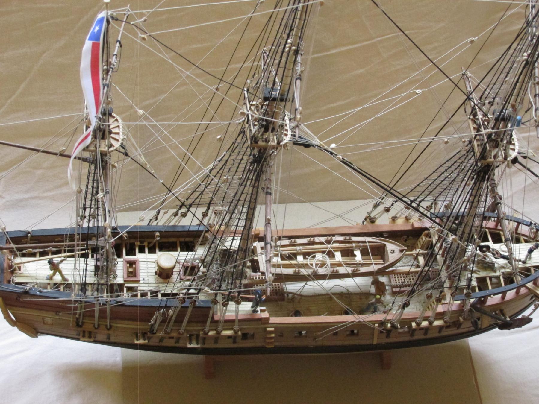
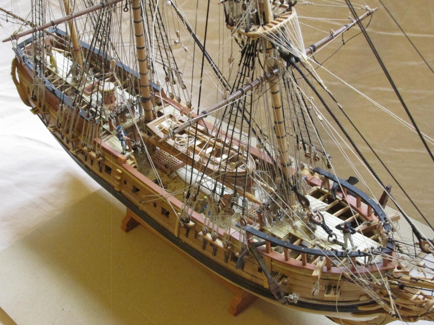
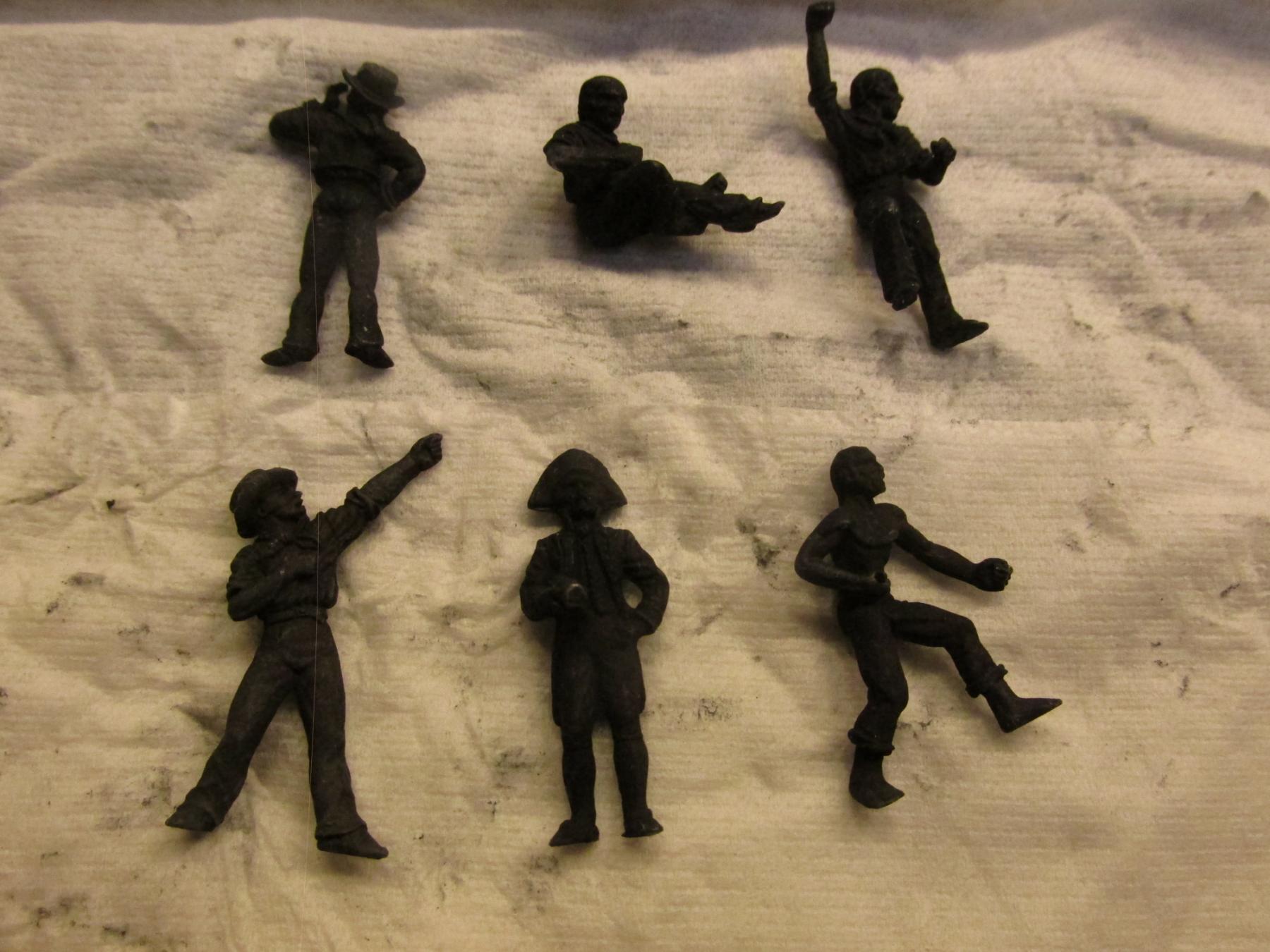
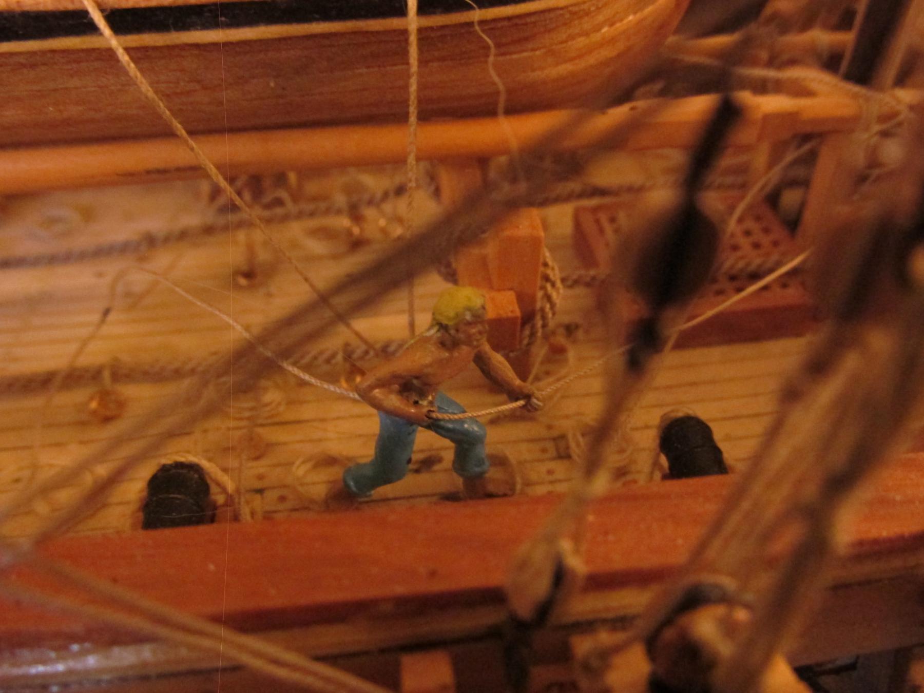
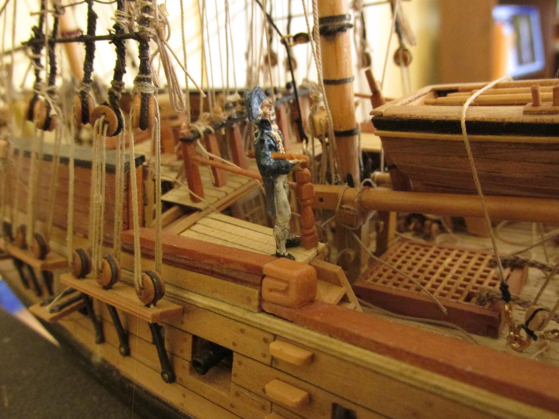
Sailor Figures
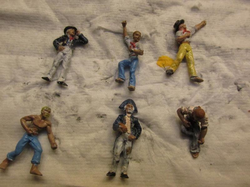
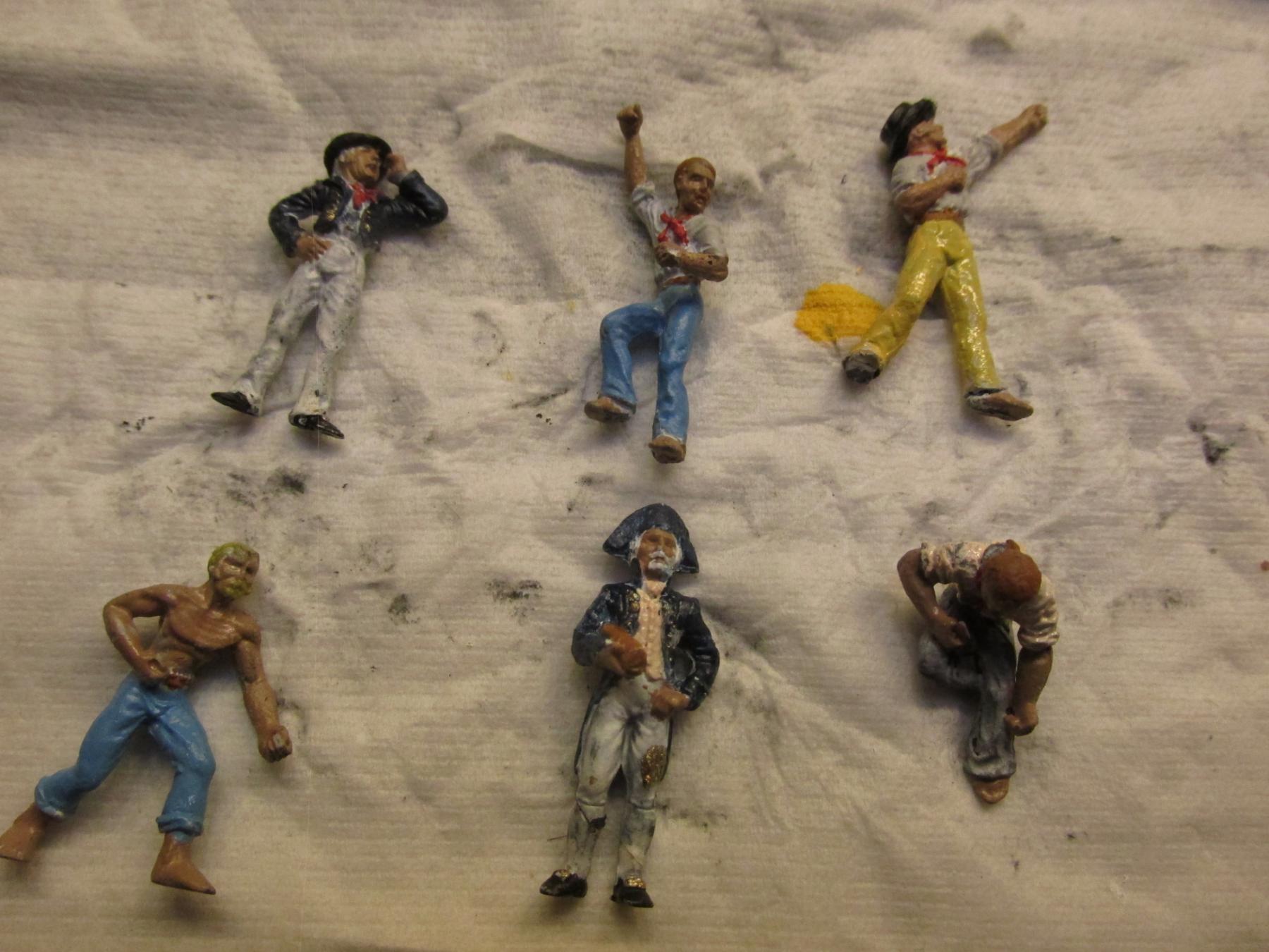
In addition to the list of things to do posted above, I forgot to mention I wanted to add some “scale” to the model so a while back I purchase some sailor figures to add to the final display. Taking a guess that the average height of a typical seaman, was 5’6” or 66”, at 1/64 scale that comes out to just a tiny fraction over 1 inch (25.4 mm). So, I purchased some Amati 25mm sailor figures. I had some 1¼” figures but that worked out to a sailor being 6’ 8”. I imagine there were seamen of that size, but not a whole crew. I found some images of typical sailor attire of the period and proceeded to do my best at painting them onto the metal figures. I prepared the figures by dipping them in the acid solution I used for silver soldering to clean them of any oils and impurities and to my surprise, they blackened (yes, I did check to see if I used the right bottle). The darkened metal did not affect the painting process.
Using flat paints, a fine brush, and my magnifiers (eye loupes and headset) I proceeded on. When I saw the photographs I am posting, I noticed my fingers left some smudges giving them the appearance of being a bit grubby, not spit and polished. That work fine for me. These guys are supposed to be privateers, not regular navy

- Duanelaker, WackoWolf, davec and 5 others
-
8
-
All my power tools are miniature: Brynes saw, Brynes thickness sander, rotary drill, and a 40 year old Dremel scroll saw that vibrates like crazy. I'd loved to get a milling machine and lathe, but as I have learned through school...the school of hard knocks, you don't buy a tool until you need it. I can't tell how many doohickys and thing-a-mabobs I've bought and never used. So I'm always window shopping and asking questions. Thanks for the prompt reply.
Jon
- mtaylor, CaptainSteve, SawdustDave and 4 others
-
7
-
Just found your log and will join all the others to follow you as you complete this arduous but satisfying journey. I hope to start building my Conny soon if I can ever finish my Rattlesnake.
A quick question: You mention earlier using small router bits. What kind of router are you using? I have jury-rigged a pseudo router thingy in the past but using the proper tool for the job is always best. Any other power tools you intend to use i.e., lathe, milling, etc.?
Jon
- Piet, Canute and SawdustDave
-
3
-
Been quietly following you from afar.
Your work bench looks familiar, hmmm, seems like I've seen it before. I know, I have one exactly like it! I got mine from Harbor Freight last year. It not a bad deal for the price.
I've always been told that to do a job right, you need the right tool and it this case I think you're going to have to bite the bullet and get a scroll saw. It will make your model building a whole lot more pleasant and more productive.
As for the wood, I try to avoid Basswood altogether if I can, it doesn't sand smooth (gets "fuzzys") and it doesn't hold an edge well. I prefer boxwood. Its a nice hard wood and a pleasure to work with.
Jon
-
I believe you have the correct idea: "center out". I tried using that philosophy when I did my rigging which I started only after I completed all my woodwork and I did run into space problems especially near the main mast. You've expanded the idea to include the deck furniture which gives you initially more room to work with. Just be careful to keep dry fitting the furniture pieces as you add stuff. Small shifts in position placements can add up so you don't have the proper location space for other stuff. For example, those deck eye bolts and their subsequent rigging around the masts can mess you up placing the spare masts in position even if they are off by only a few millimeters.
Jon
-
By definition the Sheer Strake is: "The top strake of the hull, usually following the sheer of the upper deck; located just below the gunwale. It usually follows the curvature of the deck.” So the sheer strake would be the plank just below the wale.
- cog, Canute, CaptainSteve and 1 other
-
4
-
Your model is coming along very nicely. I like its clean look. I am curious though; I don't see any ladders or gang planks to the quarter deck nor the spare masts and ship's boat. Are you planning on adding them soon? It's going to get quite crowded soon on that deck to add any construction.
Jon
-
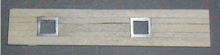
As I mentioned in my response to you on my build log, I followed Robert Hunt's practicum for kit bashing, but he also provided detailed instructions for creating the model straight out of the box. In this particular case with the gun ports, he suggested using a full plank in the middle and modified strips on either side. He provided this image:
- CaptainSteve, DocBlake, mtaylor and 2 others
-
5
-
JustBlowingInThe Wind - My kit was in fact exactly like yours... in the box. However, I bought Robert Hunt's practicum which showed me how to kit bash it. Without his instructions, I would never have attempted even to buy, let alone build such a kit. In order to follow along, I had to invest in a new wood package, new tools, books, and lots and lots of time. As it ended up, I would say that my build was at least 90 - 95% scratch built. The only thing I used from the kit were the excellent plans, keel framework, bulkheads, deadeyes, and maybe a few other odds and ends. I used Syren's rope and blocks for the most part. As an example of the kit bashing, the keel, as you noted, as well as the stem were replaced to make it more realistic.
- Martin W, CaptainSteve, KenW and 2 others
-
5
-
Just discovered your build log. I am just putting the finishing touches on my Mamoli Rattlesnake model. This is my first build and I jumped in with both feet and kit bashed it following Bob Hunt's practicum. Because it was my first build and I didn't know what I was doing at the start and I didn't know what I didn't know, I moved slower than molasses on a cold day, like 7 years. Hopefully you'll take a look at my log to avoid the pitfalls I fell into. Maybe it can can help you along.
Jon
- CaptainSteve, mtaylor, cog and 2 others
-
5
-
Just got caught up having been out of town for 10 days. She's looking real good. As my log documents I too ran into a lot of conflicts between books and the various plans I had accumulated. Not only did the Captain of the Rattlesnake not have to follow British rules, I believe he had the right to modify the rigging as he saw fit. The rigging he started out with on a voyage may not have been the rigging he ended up with when the ship returned to port.
Jon
-
Congratulations! Your model looks like you can almost "taste" its completion. Shouldn't take much longer.Ken, I like your optimism. Based on my past "speed," I'm guessing a least another month to say "done". As it is, nothing will be accomplished till after Xmas due to other commitments. Hopefully things will go smooth and I won't break anything. 8-)
To all who have endured my snail pace following me, thank you. The adventure is nearing its end, but is not quite over...yet.
Jon
- KenW, CaptainSteve, Martin W and 1 other
-
4
-
This is a big milestone: All of the rigging is installed. That being said, there still some work to be done:
· Belay all the remaining lines
· Repair:
o Rudder straps – some of the original paper ones came off
o Anchor tie down line – replace snapped line
o Gunport doors – glue back on
· Add the flags with their associated blocks and halyards
· Rework the model stand – the model wobbles too much
· Buy the cut Plexiglas for the case
· Stain and assemble the model case
· Obtain a table for the case to sit on

- CaptainSteve, DocBlake, KenW and 10 others
-
13
-
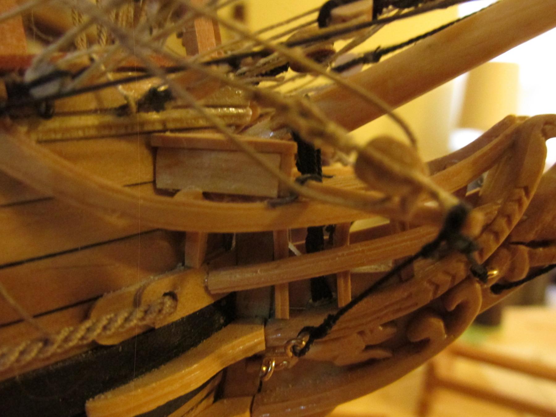
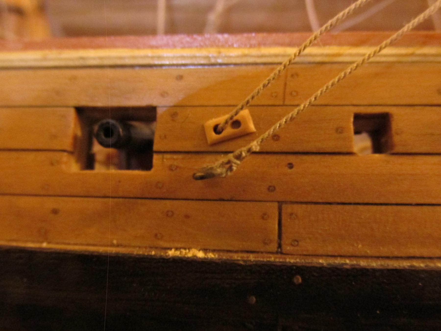
The 8 tack lines were then installed. Six of them originated from an eyebolt on the outside of the hull through a 4 mm block in the cluster and back through a hull sheave to be belayed on a bulwark cleat. The other two originated from a 4 mm block on the boomkin, through the 4mm cluster block, back to the originating boomkin block, and then to be belayed at the bow pinrail.


- Martin W, CaptainSteve, Nirvana and 2 others
-
5


USS Constitution by JSGerson - Model Shipways Kit No. MS2040
in - Kit build logs for subjects built from 1751 - 1800
Posted
USS Constitution - Model Shipway’s Kit No.: MS2040
“Old Ironsides” 1797 Frigate
Scale: 5/32” = 1 ft. (1:76.8)
This is my second POB square rigged ship; I spent about seven years building my first, Mamoli’s Rattlesnake. Like the first one, I will be following Robert Hunt’s practicum, but unlike the first, I have a multitude of excellent build logs and books to supplement it and help guide me through the inevitable pitfalls that are sure to raise their ugly heads. Hopefully, based on this and my hard-earned experience with the Rattlesnake, it won’t take another half a lifetime to build.
Now for the obligatory part. Below is the kit box and contents. I won’t bore you with showing all the little packets that are stuffed in the box, that has been done very well by numerous other builders. I will state that in addition to what came with the kit, I purchased a few more items:
· Robert Hunt’s practicum
· Hobby Mill’s wood supplement package (based on Hunt’s practicum) *
· Additional copper plate tape (as I understand it, the kit was a bit too frugal with their supply)
· 2 - 2½” x 2½” x ¾” genuine pieces of USS Constitution wood **
· Medallion made from genuine USS Constitution copper plate. Not sure yet how or if it will be used.
* Wood package purchased before HobbyMills closed shop. The supplement package was derived by HobbyMills where Mr. Hunt made his substitutions in the practicum. It was not identified as a package that could be purchased in the practicum. I have the original price list which describes what the wood is being substituted for and where in the practicum it is being described. If anyone wants a copy of the supplement wood list, please send me a PM.
** Constitution wood was purchased from the museum just before the ship went into drydock, December 2014. I have since tried to get a larger size for the keel or nameplate but accordioning to popeye2sea (who as I understand it volunteers on the ship), the US Navy is withholding any more wood from the public for now for reasons unknown. The museum told me, maybe in the Spring sometime.
This will be my third attempt at constructing this model. The first attempt was done when I was a child building Revell’s small plastic model which I really botched. I hadn’t yet learned to read and follow instructions, but just dove into assembling the parts with expected results. My second attempt was as a young teenager and when the wounds of that failed build had waned, went a bit better. This time I got the larger plastic model. I did follow instructions and even painted the parts but had absolutely no idea how a rigged ship worked let alone how the lines were attached or what they were for. It looked decent to my young ignorant eyes at the time. Both models met their demise at my hand with firecrackers; usual method of disposing such items
This time I expect a glorious finish…I hope.