


JSGerson
-
Posts
2,168 -
Joined
-
Last visited
Content Type
Profiles
Forums
Gallery
Events
Posts posted by JSGerson
-
-
As with anything you touch, it is gorgeous creation. Just perchance, did you happen to create a build log of the Constitution? I couldn't find one by you on this site. If it's on another site, I would love to see it. The Constitution is my next project whenever I finally finish the Rattlesnake.
-
Thanks for the quick reply. I wish I could use those items but I think they are too big for small lines I'm working on now. The hearts I've made so far are about 3 mm, and the thimbles about 2.5 mm brass. My main tools are a fine tooth saw, a hand drill, and a bunch of needle files. Combine that with tenacity and patience and you can make those simple parts.
- CaptainSteve and Martin W
-
 2
2
-
Scott, out of curiosity where did you order the hearts from? So far the ones that I've used, I've made myself which I admit are not perfect. Syren Model Ship Co (whose stuff I love) has hearts as small as 5.5 mm but I think that is still too large for where I just used mine.

-
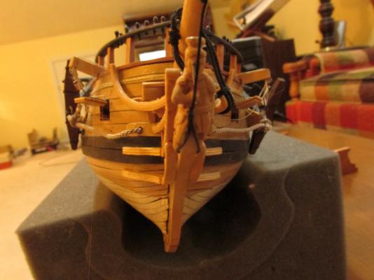
The bow end of the shrouds were attached first then the hearts were lashed together to those on the bowsprit.
- Martin W, JPett and Ol' Pine Tar
-
3
-
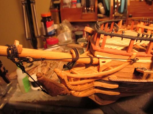
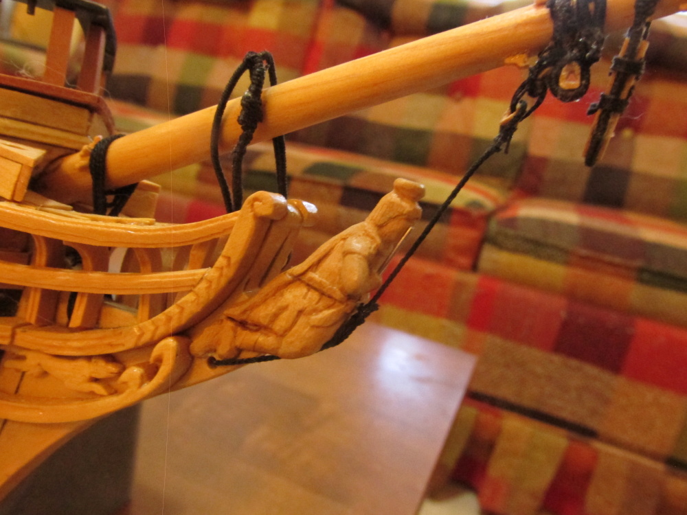
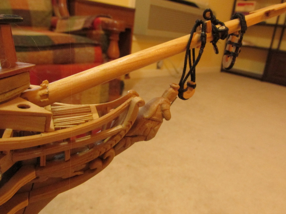
Bowsprit Shrouds
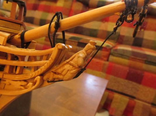
The bowsprit shrouds are fully served with one end attached to bow eye rings with an eye loop splice. The other end is looped spliced with a heart. The heart is lashed to the hearts installed earlier at the sides of the bowsprit. Although not shown on the plans, I elected to follow David Antscherl’s FFS and added a thimble into the bow eye splices.
A Piece of brass tubing was first reamed to create a conical edge to the hole on one side which was fairly easy using a Dremmel drill with a fine burr on it. The piece was then cut off the tube stock. Reaming the other side was a bit more difficult due to its tiny size. For that, I used a button reamer hand tool. With a fine file a groove was filed into the edge of the ring to hold the line in place. Since the edge was going to be covered by the line, it didn’t have to look good, just be functional.
BTY: The burrs I used in the Dremmel I got from my Dentist. I asked him what he did with his drill bits/burrs when they wear out and he told me after he uses them once, he tosses them. After I told what I wanted them for model making, he collected a week’s worth for me and now I’ve got a “lifetime” worth! These are diamond coated burrs in various shapes and sizes and looked brand new.
-
Bobstay
The Bobstay is a fully served line with one end passing through the stem and fastened to itself in front of the figurehead as a long loop splice. The other end is looped spliced with a heart. The heart is lashed to the heart installed earlier under the bowsprit.
- CaptainSteve and Martin W
-
2
-
-
There are two sources for the belay pins I know about
- Visit the ship in Boston
- Anatomy of the Ship, The 44-Gun Frigate USS Constitution, "Old Ironsides" by Karl Heinz Marquardt
I think getting the book would be a bit easier 8-)
-
-
Thanks for the kind comments Martin. The Seat of Ease is based on Pasi Ahopelto's model (before the site crashed). He has since resumed his log but he has not re-posted all that was lost. At the time I was constructing it, I had not seen (or at least recognized) one on other models so I followed him. Now I see that his design appears to be a bit unique in the triangle shape. Still, it works for me.
-
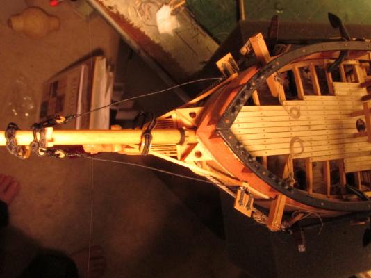
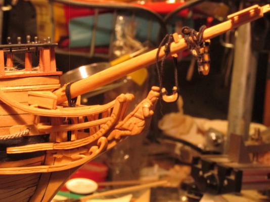
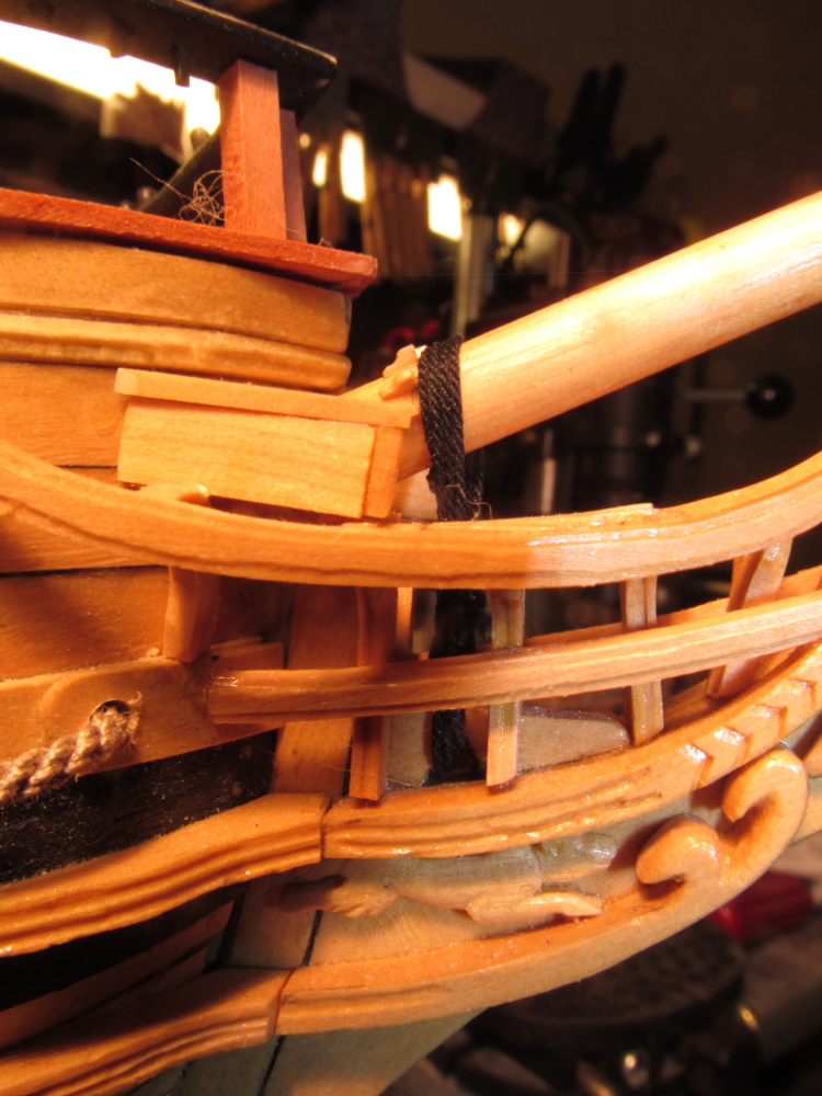
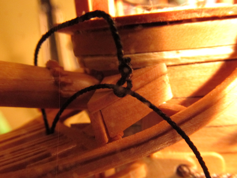
Then it was wrapped around the vertical lines horizontally half way down under the grating. The horizontal turns were supposed to equal the number of vertical turns but elected to do only two. The space was quite cramped and even with a light aimed directly in there, it was hard to tell there was any wrapping at all.

-
Using .45mm Syren Ship Model Company black miniature rope, the gammoning, was started with an eye splice and then threaded through the grating, through the gammoning hole in the stem, and back up top four times.

- Martin W and CaptainSteve
-
2
-
-
My skills? I have never done this stuff before! I'm learning as I am going which is why I'm moving as slow as I am. I just taking one step at a time, trying to make as few errors and do-overs as I can, but no matter how I try, I make a bunch of them...I just don't post most of them 8-)
- CaptainSteve and Martin W
-
2
-
Sorry for the delay in responding but I was at the NRG Conference in St. Louis last week and just got back today (19 Oct 14). Trying to respond to email on an iphone is hard on the eyes. I don't know how those young kids do it. So onto your question. I had a great time by the way.
I can't take credit for the method I showed. I am following Blue Ensign as he builds the HMS Pegasus (starting at comment 696 for the foot ropes) who by the way credits Gil Middleton for the pseudo (my term) splice. See, we all help each other. See if Blue Ensign's more detailed descriptions help. If you still have questions, please feel free to ask me again.
-
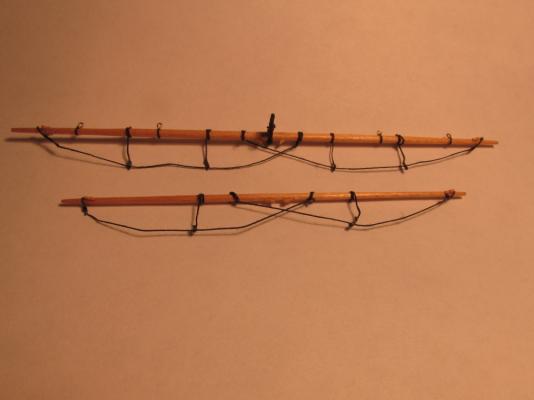
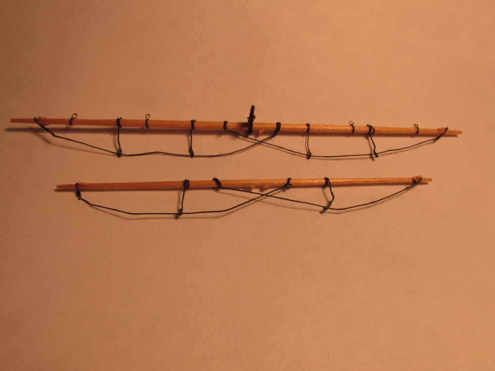
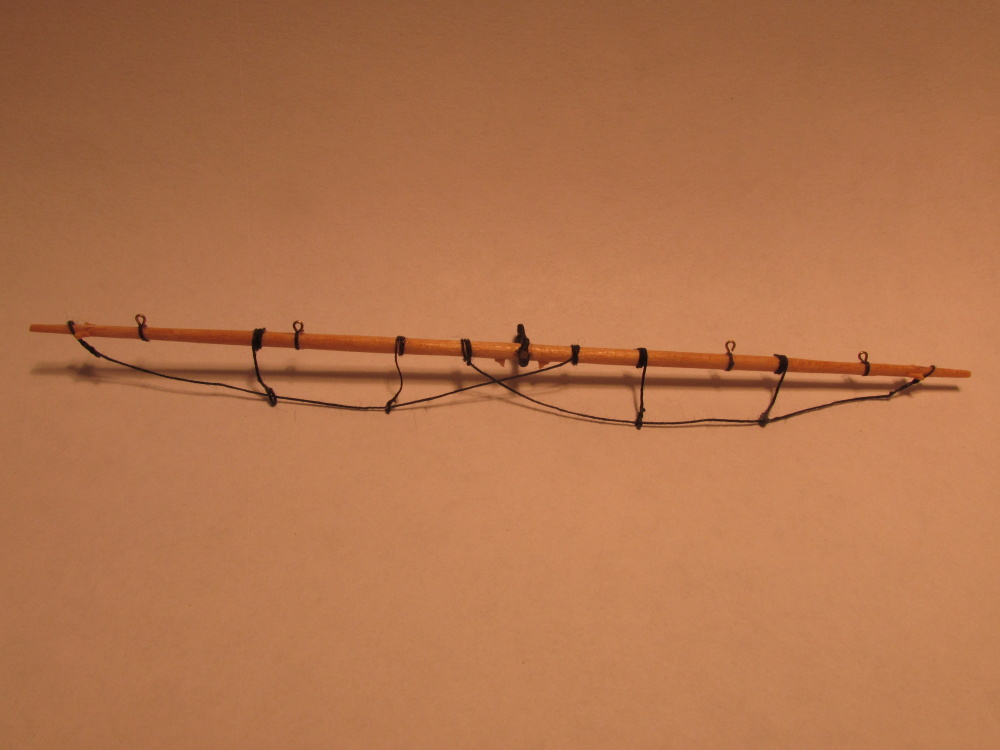
Spritsail Yard and the Spritsail Topsail Yard
- CaptainSteve, JPett and Martin W
-
3
-
I went through the same loss of images problem as well. If any of the photos were posted by a commentator, not yourself, then they must re-post. I still have images missing because the originator of the images never re-posted. BTY, on page 28, comment 417, two images are still missing.
I really have learned an awful lot from your blog and always look forward towards your next installment!.
Jon
-
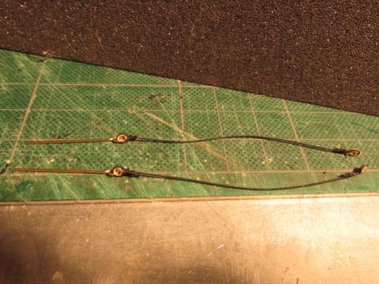
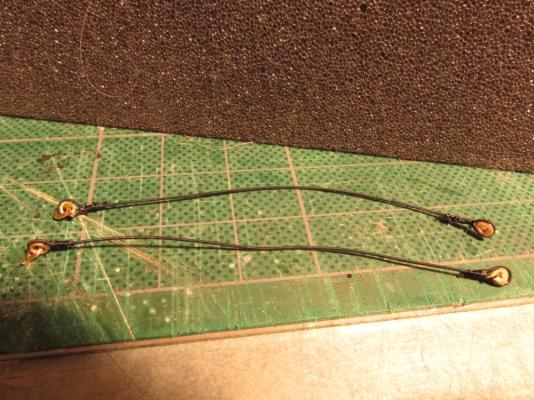
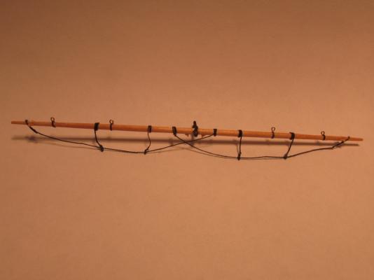
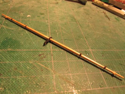
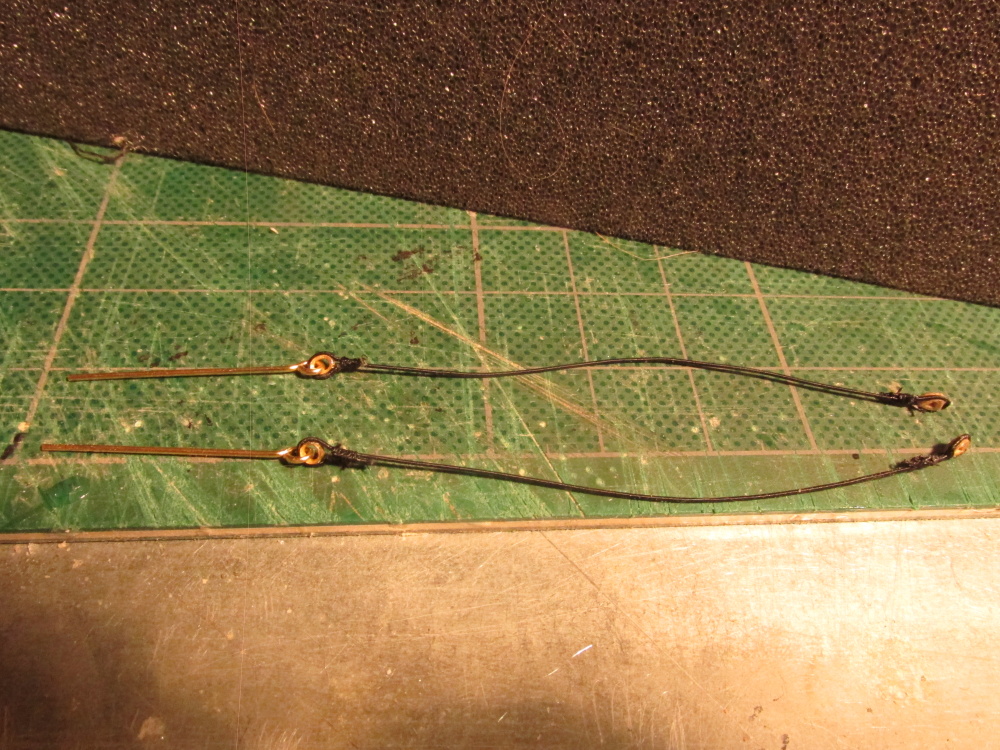
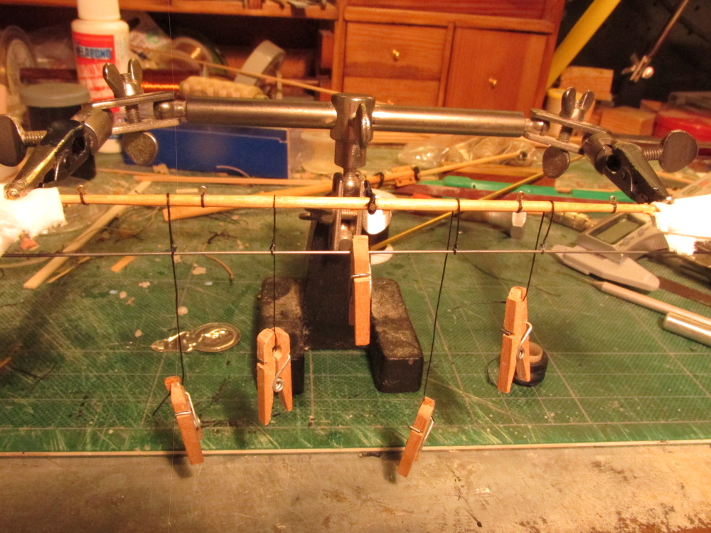
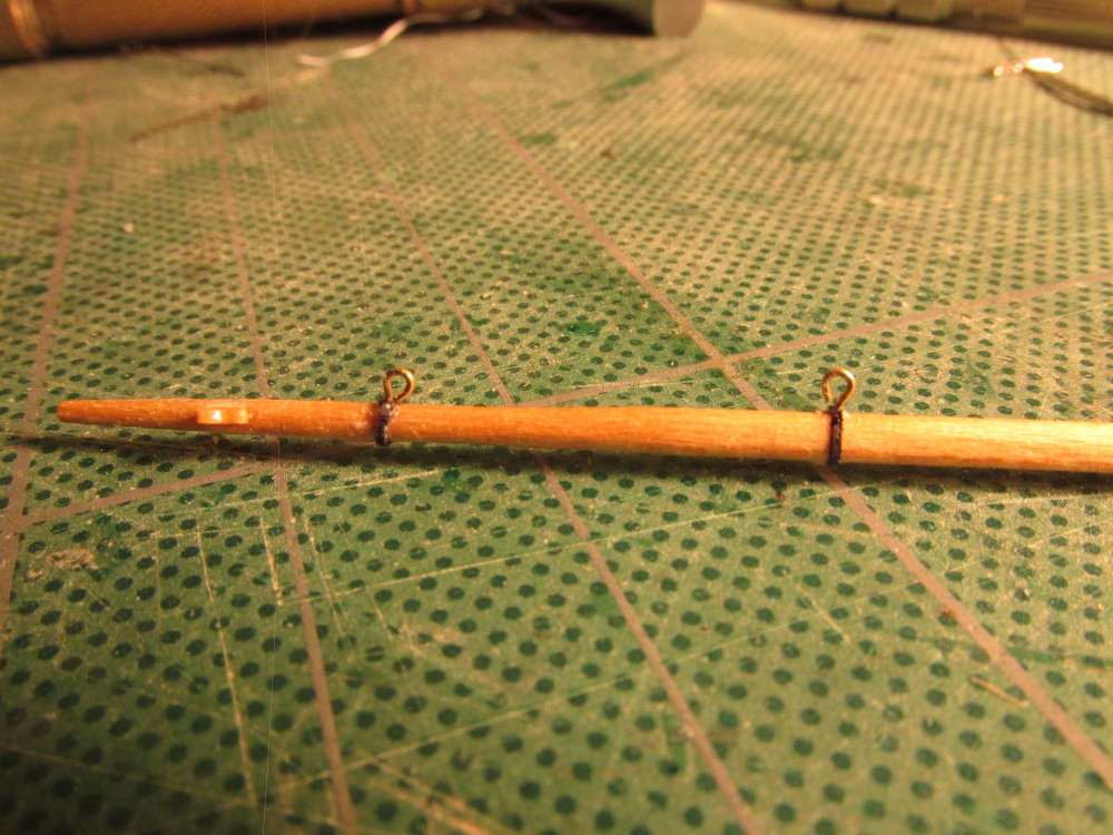
After everything had dried and the excess lines trimmed, the music wire was removed leaving four hanging stirrups perfectly vertical, properly spaced, and horizontally even. The foot rope had a pseudo splice made at one end to slip on the outer end of the yard. Once the foot ropes were threaded through the loops using a needle threader, the inner end was wrapped around the yard itself like the stirrups.
- Martin W, KenW, Geoff Matson and 4 others
-
7
-
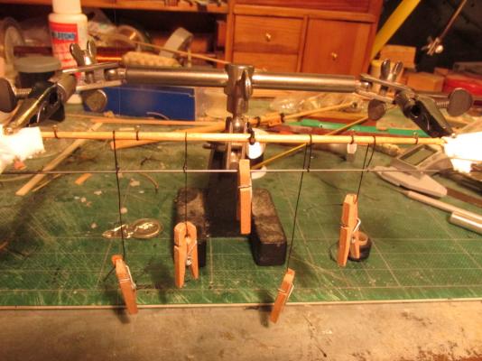
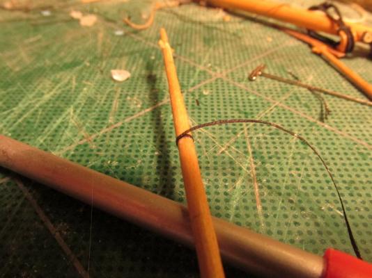
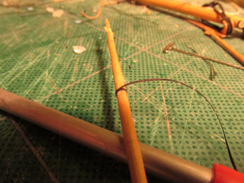
Once I had four stirrups made and wrapped around the spritsail yard in the proper position, I inserted a music wire which had the same diameter as the eyelet through the stirrup loops and made sure everything was level and even. I used a clothes pin to add some weight to the wire to keep the stirrups taut. The wrappings around the yard were then glued into place and the vertical lines were “painted” with diluted PVA glue to stiffen them up.
-
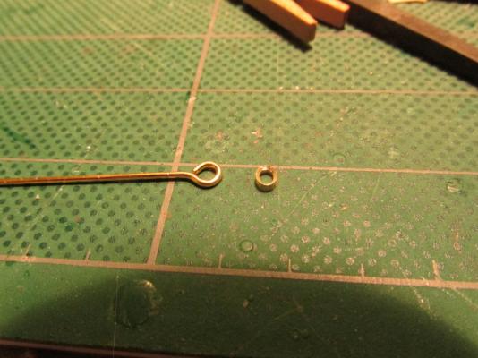
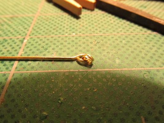
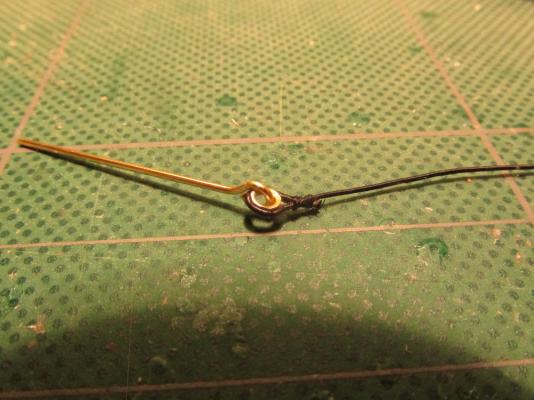
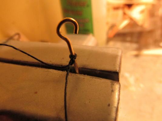
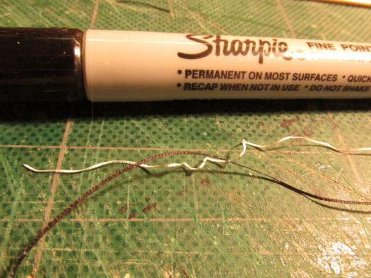
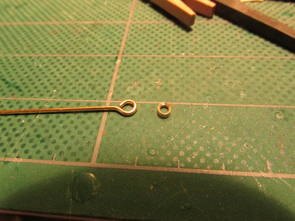
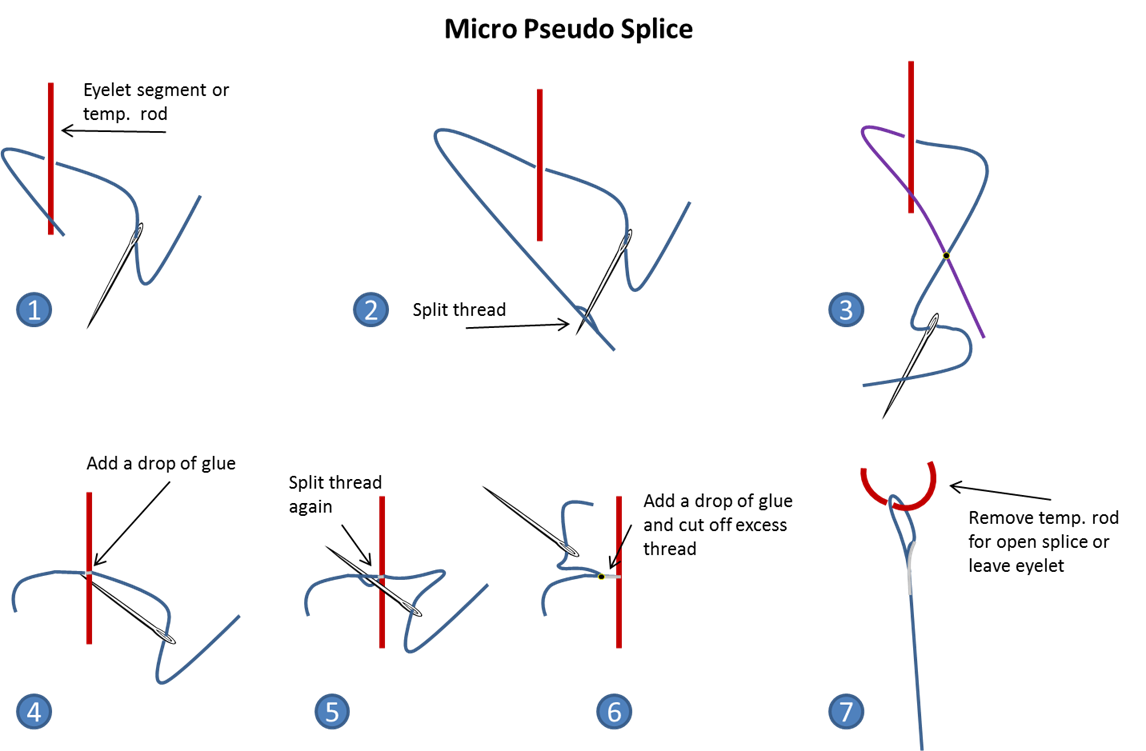
The methods work well to add a loop splice to an eyelet or in this case just an open loop. To create the open loop, I used the long end wire of an eyelet. When completed, the loop was slid off leaving an open loop.
- CaptainSteve and Martin W
-
2
-
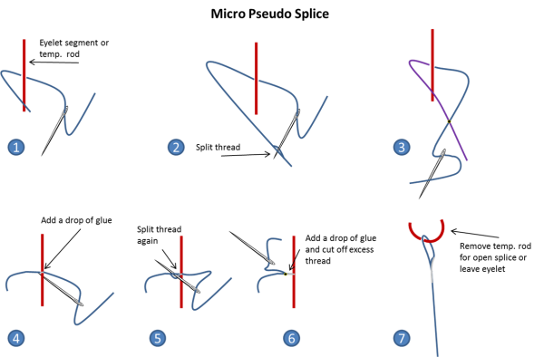
After doing a bit of research (thank you Blue Ensign and Gil Middleton) as to how to make the stirrups and foot ropes, I came across (for lack of a better term) the Micro Pseudo Splice. I looked at a number of builders’ methods and this seems to be the best (to me at least). Because of the small scale, making a real splice is neigh impossible and making it look to scale. This method is real simple (because even I could do it) and the results are clean. I drew up the method as shown below.
- cristikc, CaptainSteve, GuntherMT and 2 others
-
5
-
I've discovered another method for applying the "caulking" paper to the planks. Start with a sheet of wood the thickness of the required planks width and veneer a sheet of paper (your choice of color) on top of it. Then slice planks to the width of the thickness of the desired plank with a Byrnes Saw (or similar). When the strips of wood are rotated 90 degrees, the paper/caulking will now on the vertical edge. No more applying paper to individual pieces of wood; dozens of planks can be made at a time.
-
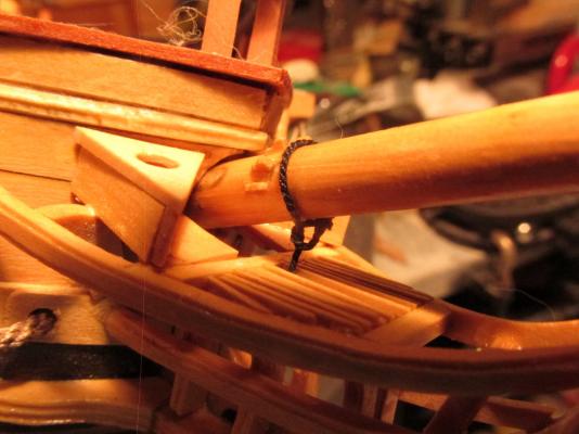
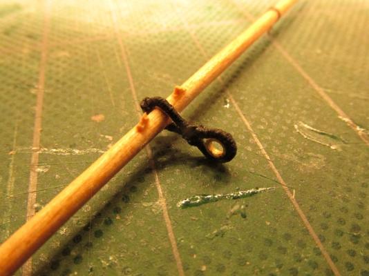
The spritsail yard has rings on it for the guy pendants. Actually they are thimbles on a metal band that wraps around the yard. To simulate this, the metal band is simple thin strip of paper cut from some plain copier paper and colored black with a Sharpie pen. The eyelets that came with the Mamoli kit are 3 mm f which I thought were way out of scale so I used ones which were about 1.5 mm to make the thimbles.

- KenW, CaptainSteve and Martin W
-
3
-
A piece of the tubing was then cut off from the stock material about the same thickness as the seized line. Using tools I bought for making jewelry, I used a bead reamer to flare out the inside hole of the brass “donut” on each side and filed a groove around the outside edge to hold the line in place. Then it was just a matter of placing it inside the line loop.
It was at this point I realized I now had a problem as how was I going to get it on the yard. This component should have been made and installed before the cleats were glued into place. Then the line would have been formed into a circle with a pseudo splice. The circle would have been cinched and seized to form a figure 8 with a smaller loop on top for the thimble. The larger loop would then slide onto the yard. Of course the dimensions of the initial circle would have had to been dead on.
But I didn’t do it that way. Instead I had to glue in increments first to put it into position and then to wrap the two open ends around the back to cut them to size so that they would butt up to each other. Then I glued them down.
Maybe the way I did do it was easier, I don’t know.
- CaptainSteve, KenW, GuntherMT and 1 other
-
4


USS Constitution by robnbill (Bill) - FINISHED - Mamoli - 1:93 kit - First Build - Bashed
in - Kit build logs for subjects built from 1751 - 1800
Posted
If you didn't do it, you would never be happy with the model. Biting the bullet can be bitter but the end results are much sweeter.