


JSGerson
-
Posts
2,166 -
Joined
-
Last visited
Content Type
Profiles
Forums
Gallery
Events
Posts posted by JSGerson
-
-
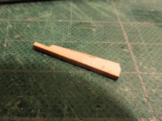
After looking at a lot of small and ship’s boats, I came to the conclusion that most of the boats I saw did not have the high stem post, so I chose to leave it off. Had I straight glued the broke piece back on, it would have remained fragile which would mean I would have had to pin it and risk breaking it some more.
All that being said, the rudder was now too tall for what I wanted to do so, the tiller post was cut down a bit.
-
-
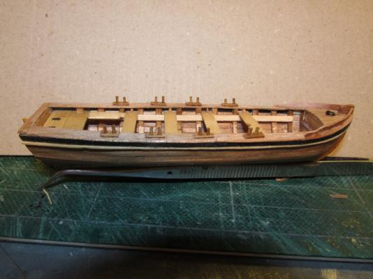
A strip of wood, which I think is called a washboard, was added to each side of bow as well another eyebolt and ring to the bow deck. Also notice that the oarlocks were moved after I was informed that I had inadvertently installed them on the wrong side of the thwarts. As originally installed, the rowers would have to face forward and row the boat backwards.
-
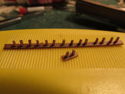
The oarlocks were made of bamboo pieces just like one would make treenails, about a quarter the width of the soon to be made oars (about 1/32”) and placed into a pre-drilled kit supplied basswood planking strip. Initially the holes were drilled and the oarlock inserted. Their heights were adjusted and then the whole assembly was stained with Early American. The stain temporarily “glued” the bamboo into position. After the stain dried, the excess was cut off from the bottom and sanded smooth. The oarlock assemblies were then cut off and glued into position onto the rail cap locking everything – the rail cap, oarlock plate, and the bamboo with a single dab of CA glue.
- CaptainSteve, hexnut, justsayrow and 1 other
-
 4
4
-
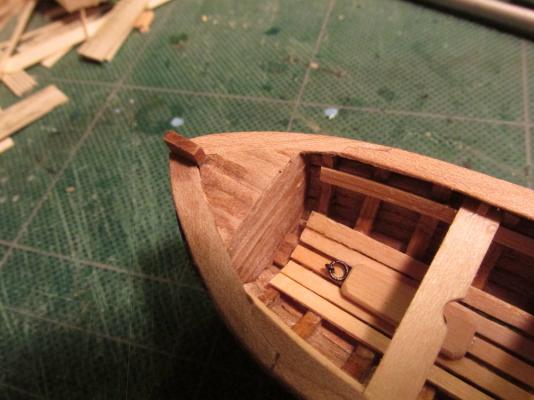
The bow was covered with teak plank.
-
These were glued in place, trimmed and sanded.

-
The top rail was made using a template traced from the model. If I had made the model perfect it would have matched the plans and I could have just cut the template directly from them. Since it wasn’t, I couldn’t. Each side template had to be cut in two places to create the splines for the three pieces of 1/32” x 3/32” Teakwood to accommodate the boat’s curve. The top of the transom was ¼”.
-
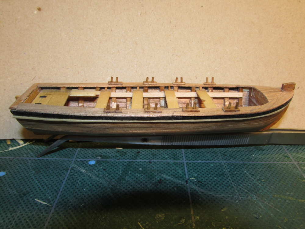
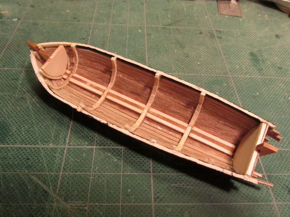
I noticed on many models, that the thwarts had little braces (knees) securing them to the hull so I added those. I tried to round the corners, but they were so tiny I could barely hold them steady, let alone file them. As it turned out in the end, you can hardly see them.

-
The seat pieces were cut and trimmed to fit and glued into place. The “hinges” are nothing more than pieces of black paper that were added when I Poly-wiped the wood. The remainder of the thwarts (seats) were supported by the risers (support strips). The forward thwart had a half round notch cut out for an optional mast.
- mtaylor, themadchemist, olliechristo and 1 other
-
4
-
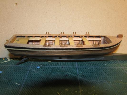
It seemed to me that all ship’s boats are basically the same at this stage of the build. Looking at all of my 46 Rattlesnake models images that I have collected from the internet, I selected the ones with clear/detailed images of the ship’s boat. Not one of them duplicated any other’s boat. Everyone was different. That meant I had free rein as to what mine was going to look like. Taking elements from the kit itself, the Practicum, other boats on or off the Rattlesnake, and reference books, I came up with my version.
Like most boats, I created a backseat with two side seats. Some of the models I had seen had a lid over the back seat so I thought that would be neat to have. The lid was simply etched into the wood. Additionally I added a mast block (my own design since I didn’t have much to go on) and some brass rings fore and aft colored black with a Sharpie pen.

-
At this point I decided that the exterior still needed something, so I added a piece of unstained 1/32” x 1/32” basswood right up against the sheer plank. It did two things. First it added a little snap to the boat. I had seen other small boats with similar structures. Second, it covered up small gaps between the planking and the sheer plank. The basswood piece was cut from the 1/32” x 3/32” basswood planking stock that came with the kit. I actually made two strips from one plank! Boy, I love that Byrne’s saw!

- mtaylor, alde and themadchemist
-
3
-
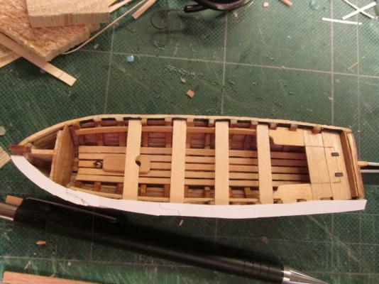
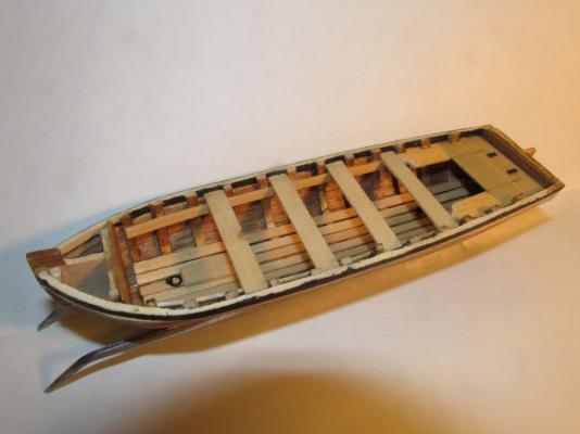
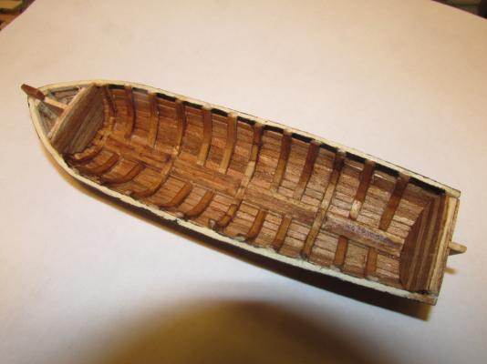
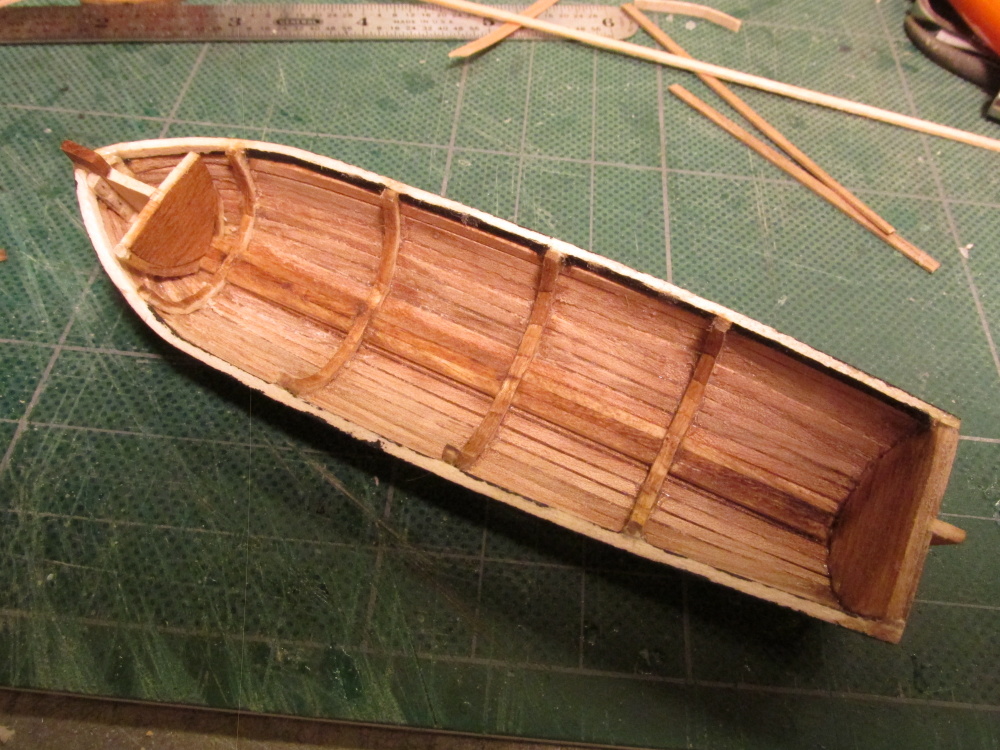
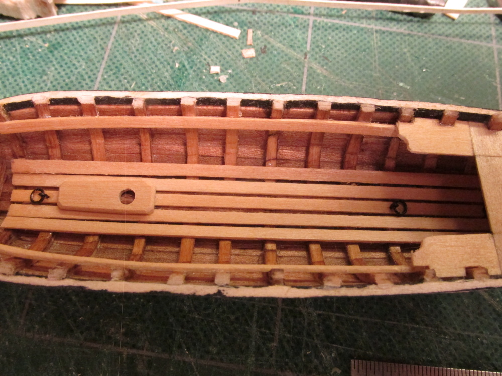
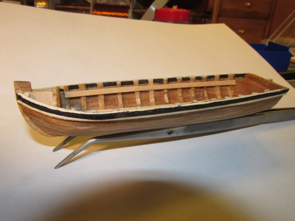
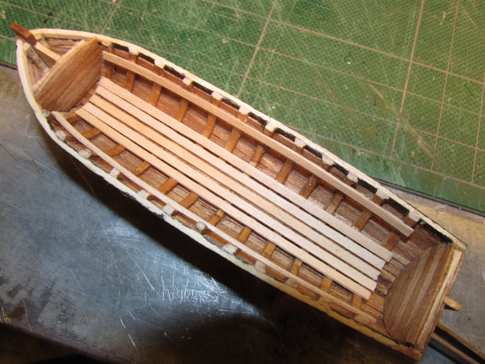
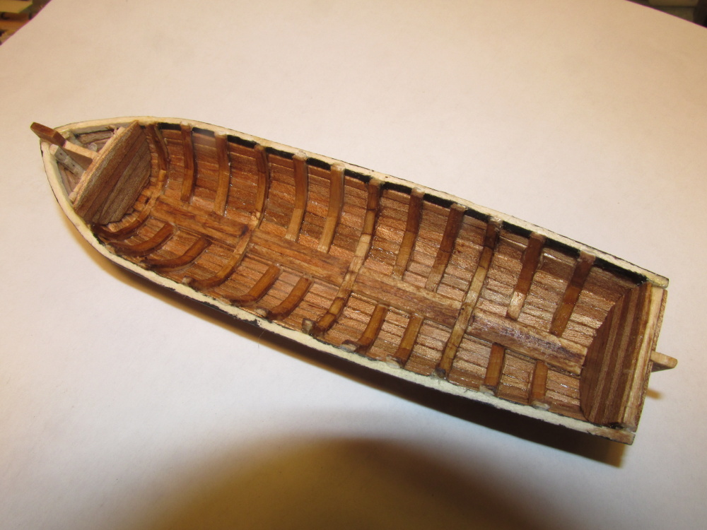
Basswood planking stock was added as the interior floor boards and for a change, there were no hassles. I left this basswood as well as the other basswood in the interior unstained to provide a contrast between the interior and the exterior of the boat.

- mtaylor and themadchemist
-
2
-
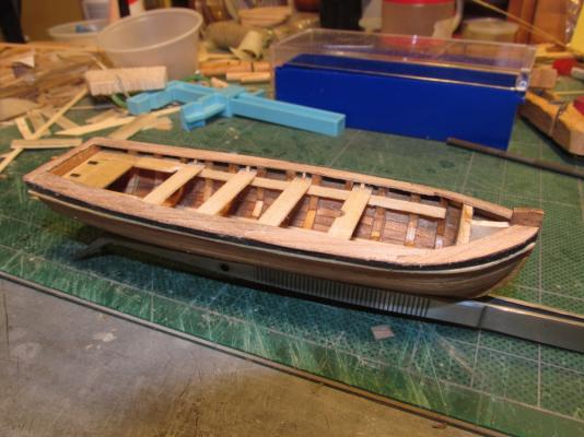
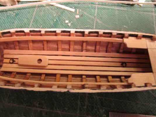
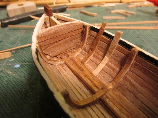
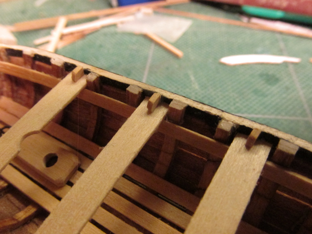
Following the kit plans, additional ribbing was added. The ribs were made of the kit’s basswood but not the bass designated for it. Instead I used the unused planking material which was half the intended thickness. Two pieces were cut to size, soaked, bent, and laminated together. The bending was much easier that the original ribs on the building jig. They were glued to the inside of the hull, trimmed, and stained. The whole hull was then coated with Wipe-on Poly.


- Martin W, themadchemist and KevinR
-
3
-
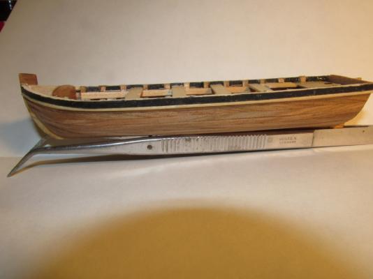
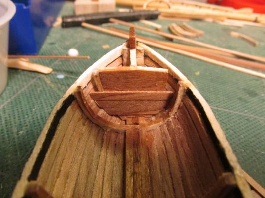
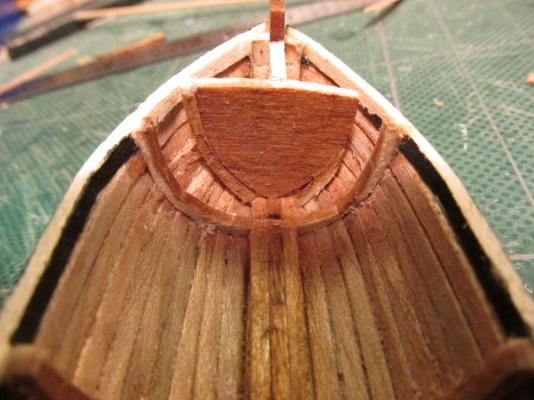
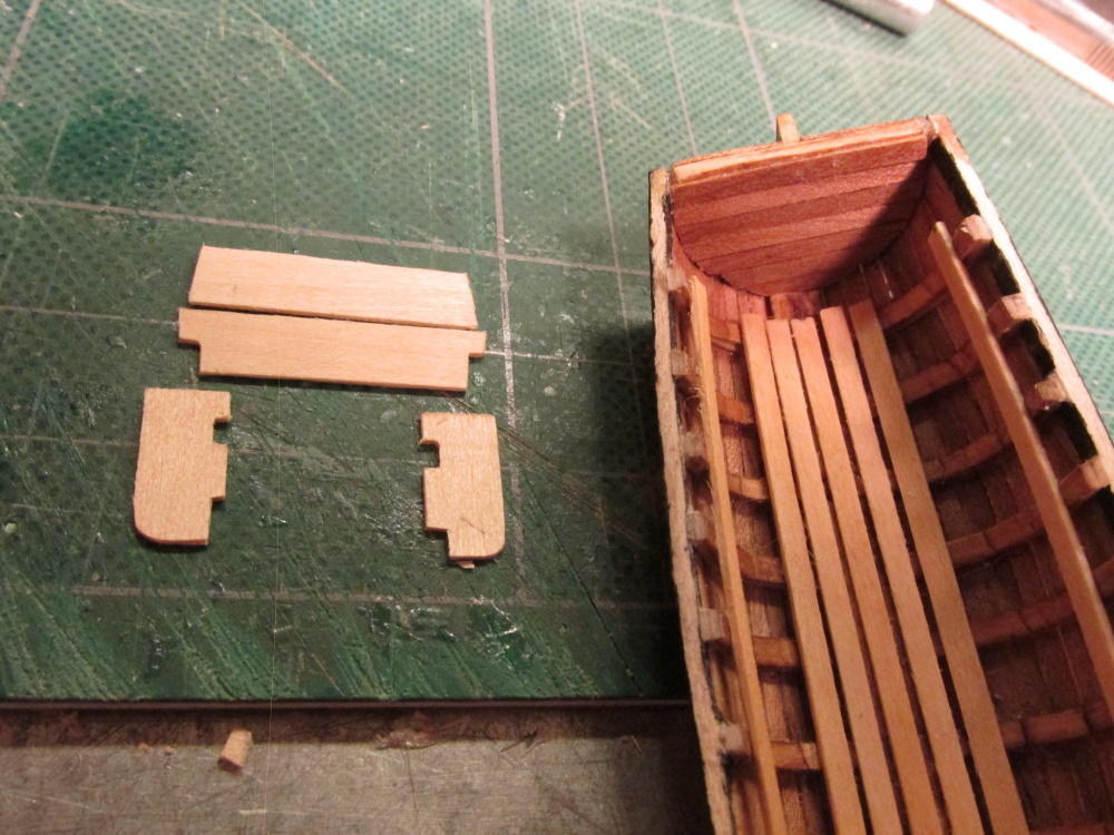
Using the Teak planking I made for the hull, a new bulkhead was veneered over the original. The same was done to the transom to match.
- KevinR and themadchemist
-
2
-
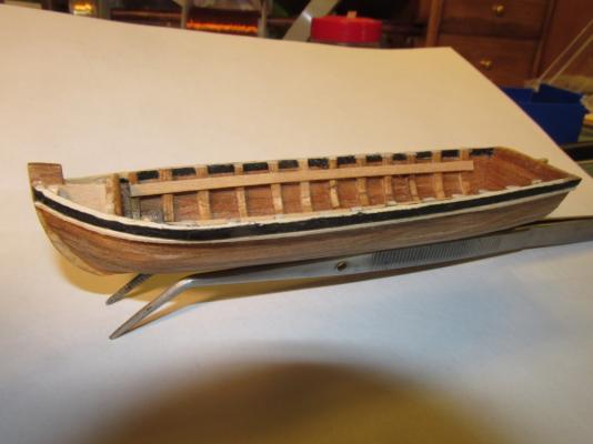
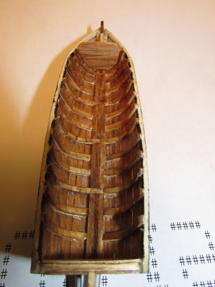
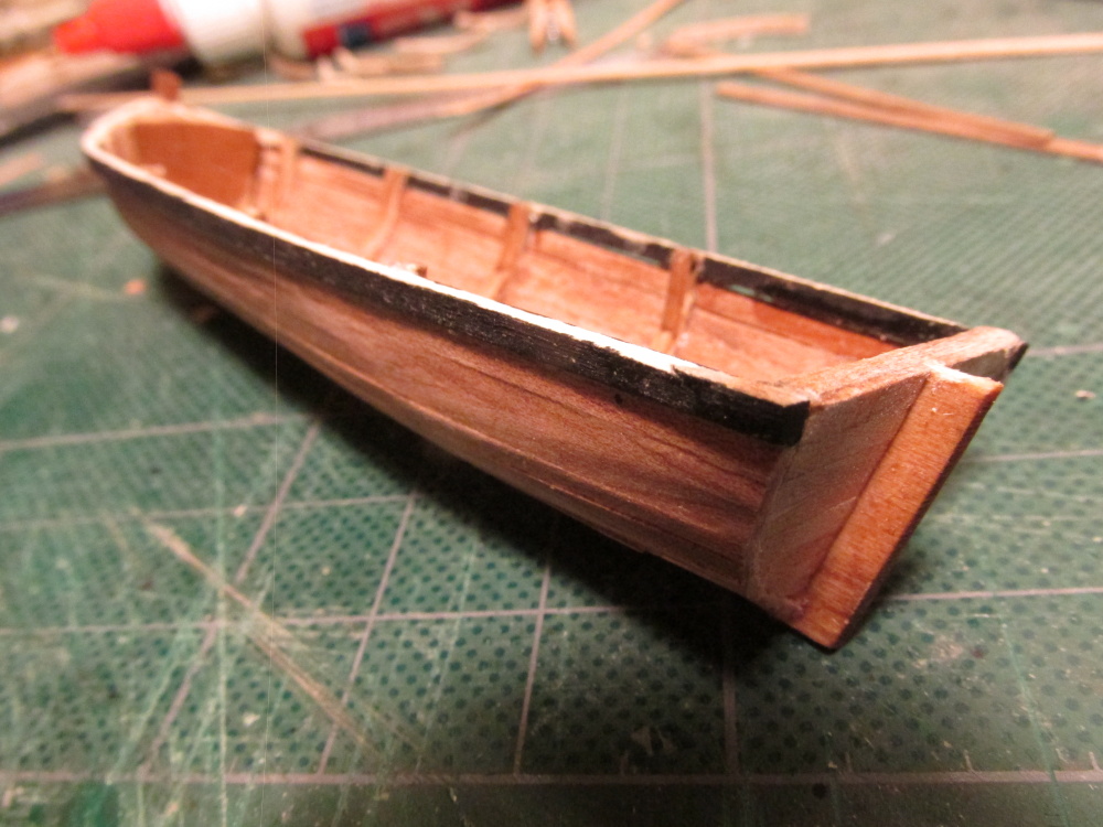
You will notice that the pre-cut bow bulkhead was too small and I had to beef it up during planking so it was not a pretty sight.
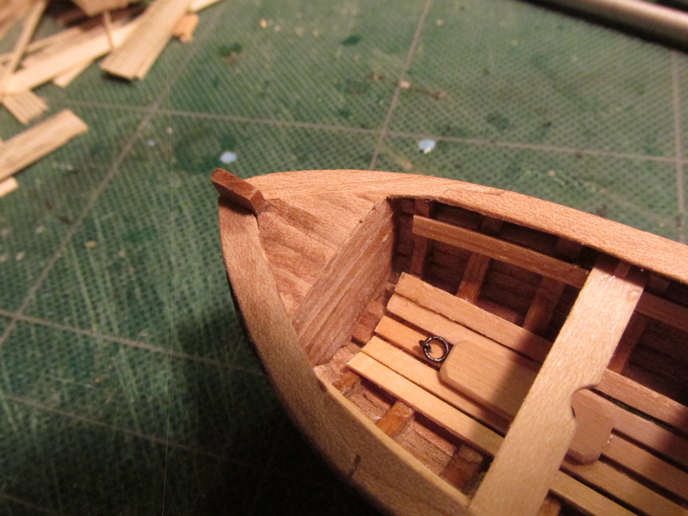
-
The excess planking was removed at the stern, but in the process the unsupported stem post above the hull broke off. That was because the grain of the wood was horizontal so it had no strength. A sneeze could have knocked it off so it wasn’t unexpected. If the stem post had been constructed like a real boat, the grain would have been vertical but because this was a very cheap kit (I paid $5.00 on sale, otherwise $8.00) a lot of detail was spared. I will address this later.
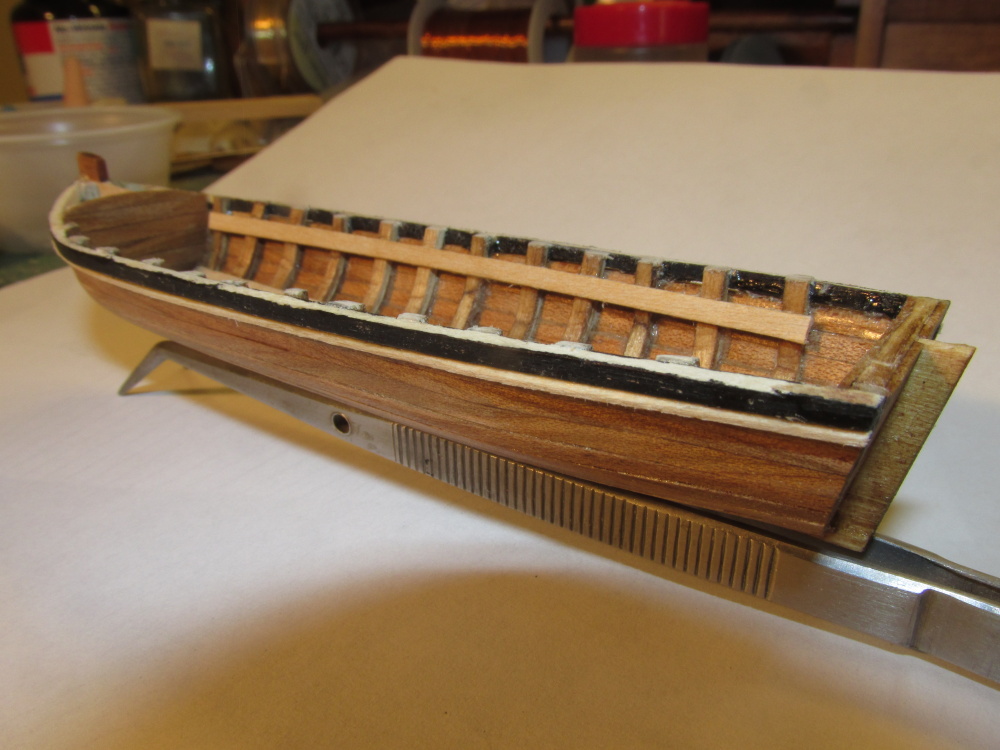
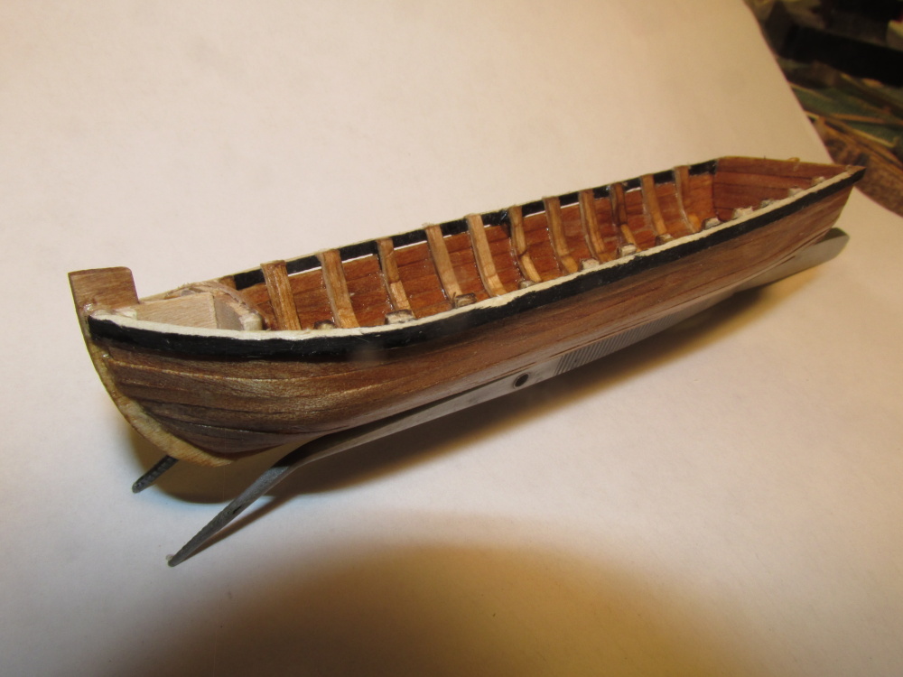
The light colored basswood ribs and keel looked like tan lines against the darker Teak so I stained them with Early American 230 Minwax Wood Finish (what else?) to match the Teak.


-
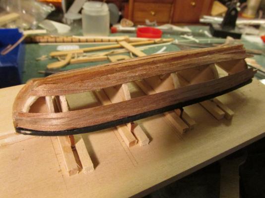
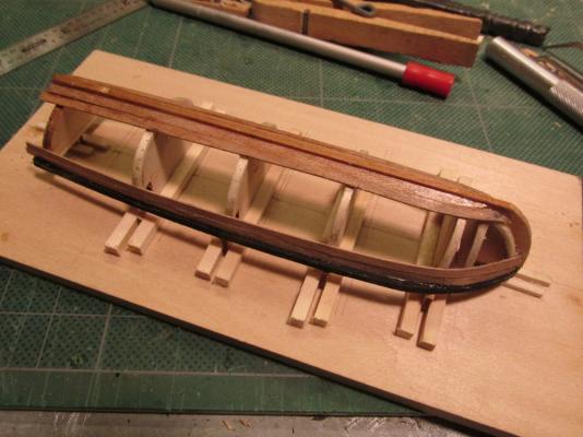
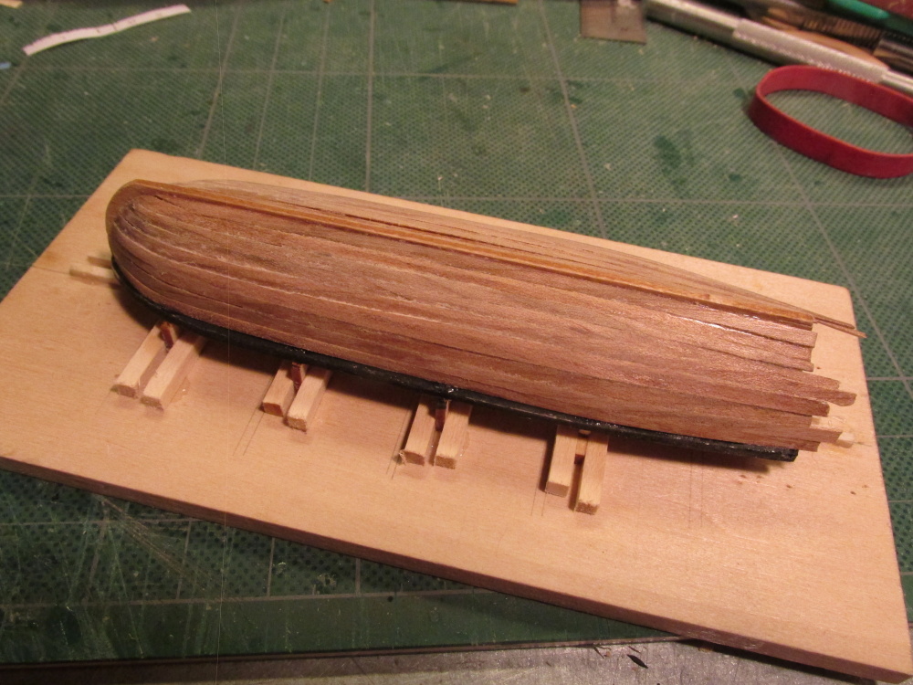
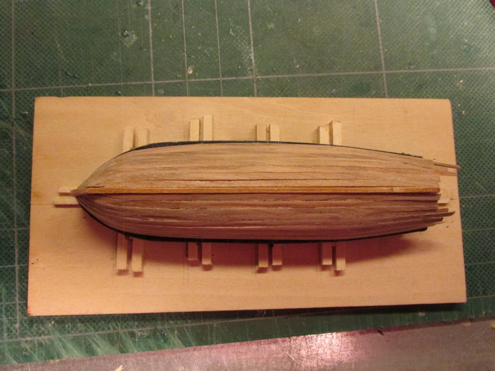
Spud1 - There was no real problem removing the hull from the jig. The only thing holding it down were the ribs which extended into and were glued to the jig. Since they were basswood, they were easy to cut. There was one causality, the rudder post. Because the keel included both the stem and the rudder post, the grain of the wood ran horizontal at these points. Because of this, all one had to do was was breath on the rubber post and it would snap off, which it did. I will discuss all of this in my next post.
-
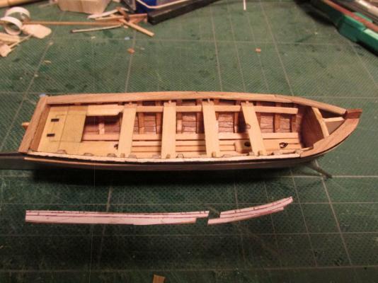
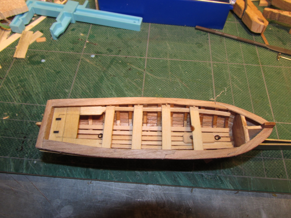
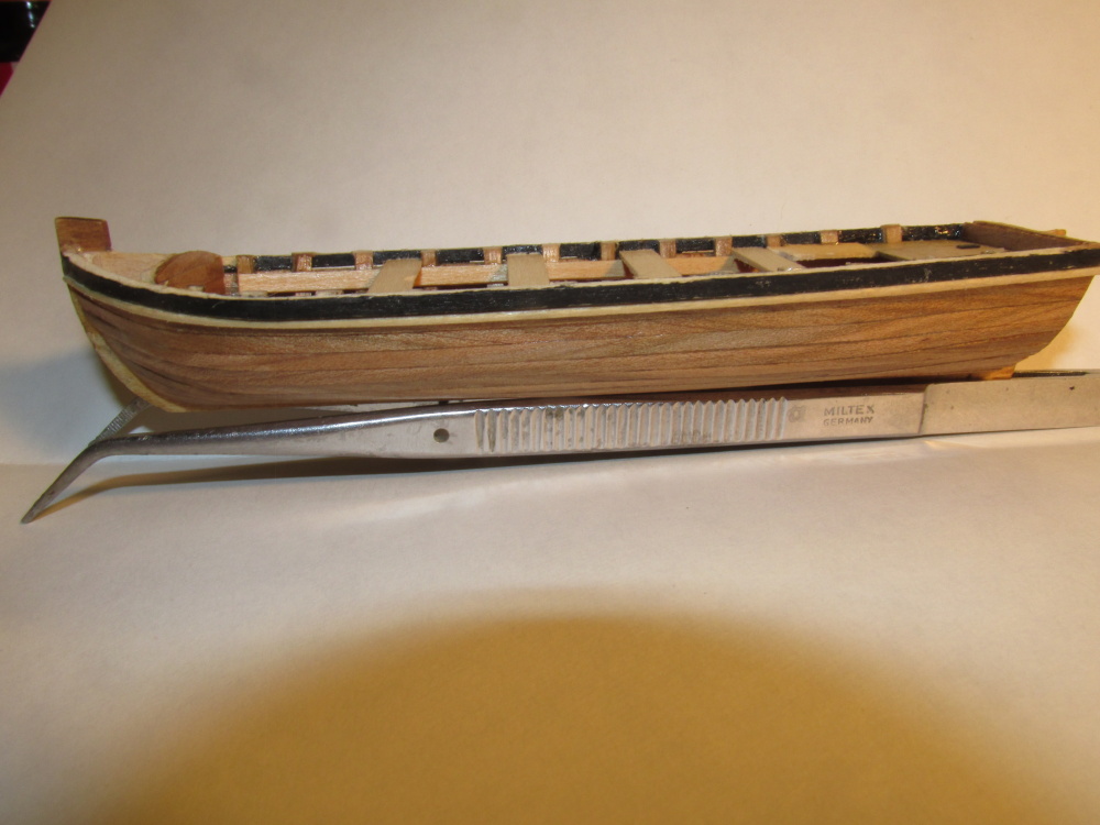
These final shots of the boat show the raw planking complete. The last shot, the boat has been removed from the building jig. The outside has had a preliminary sanding. The planks still hang over the stern and the interior desperately needs to have excess glue removed and sanded. No treatment to the wood surface has been applied yet.

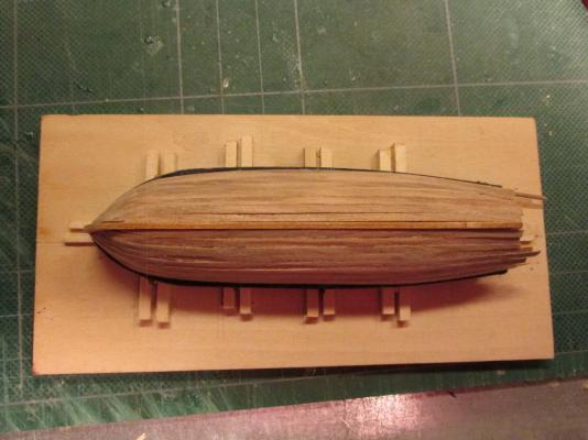

- alde, themadchemist, KevinR and 5 others
-
8
-
It’s been a while since my last post, but progress has been made. Slowly I applied the planks, removed them and applied them again trying to keep the fine gaps between the planks at a minimum. Due to their thinness, the planks have a tendency to bow between the ribs. It would have been a lot easier to plank had there been more ribs.
- Martin W and themadchemist
-
2
-
The result was a strong 1/16” x 1/16” strip in perfect shape. After a little sanding and trimming, it was glued into place.
- WackoWolf, sport29652, Martin W and 1 other
-
4
-
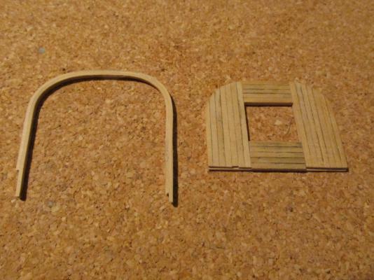
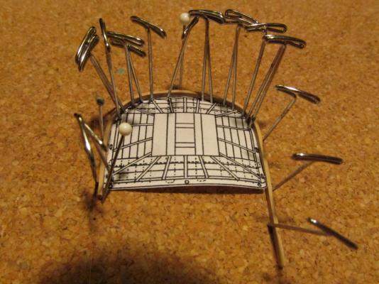
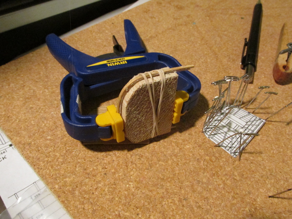
Grabbing a “spare” piece of boxwood stock (if I run out later, I’ll buy some more), I milled 1/16” x 1/32”strips, half the thickness called for. After a half hour these were ready and pliable. Instead of the pins, using some balsawood, I made a form in the shape of the platform. I laminated two strip pieces together with WeldBond and wrapped them around the form This glue gave me plenty of time to set it up and clamp before the it dried.

- Martin W and sport29652
-
2
-
NOTE: For those faithfully following this log, I apologize for going at a snail’s pace. Each step for me is new territory and although I try not to make too many mistakes, it seems to me that although I may not repeat too many of them, it seems to me that I have made every one of them at least once. So bear with me as I plod along; there is no rush.
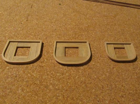
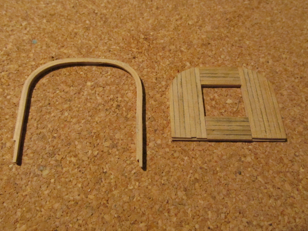
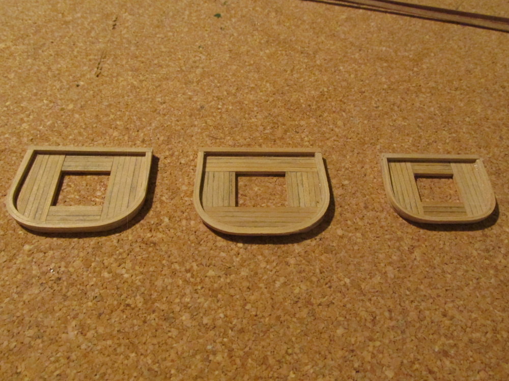
Using the Hahn’s platform drawing as a template, the curve of the platform was traced onto the platform construction and the excess was then trimmed off. I used a disc sander. The platforms have a perimeter strip which is made in two parts. The back piece is simply a 1/16” square strip glued to the edge. The remainder is one long strip that is bent to shape. Mr. Hunt stated in the Practicum that he soaked his piece for 30 minutes to get it pliable enough to bend and glue, bend and glue in place using CA glue. I don’t know what kind of magic he was casting but that didn’t work for me.
Initially I tried soaking the boxwood strip 2 days and then wrapping it around pins following the template I made earlier. As careful as I was, using both the heating iron method and a plank bending tool that make fine creases on the inside of the bend, the strip broke in two places due to the tight curve. I had the same problem when I was making the ribs for the ship’s boat. If there is some technique that makes this work, I don’t know what it is. It was time to be innovative.
-
-
The two planks next to the sheer rails were reinstalled. Additionally I installed the garboard planks and the planks next to it but not until I did that twice. It’s not perfect, but it’ll do. All of this was going on while I had my problems with the Rattlesnake’s mast tops (see log). Boy, was I having fun!


Ship’s Boat by JSGerson - FINISHED - Model Shipways
in - Kit build logs for subjects built from 1751 - 1800
Posted
I had noticed that a lot of tillers pivoted vertically either for storage when the rudder was removed or for easier access to the boat. Although I didn’t plan on mine being functional, I wanted it to look like it could move. This required two short pieces to be added to the tiller post. The tiller itself was carved with a slight S-curve.