


JSGerson
-
Posts
2,163 -
Joined
-
Last visited
Content Type
Profiles
Forums
Gallery
Events
Posts posted by JSGerson
-
-
Two holes had to drilled for the sheave at the top and a square hole at the bottom for the fid. The square hole was made by drilling the appropriate size hole with my Dremel drill press and then cutting out the corners. One can’t tell, but the “squareness” of the hole is just near the surface.
-
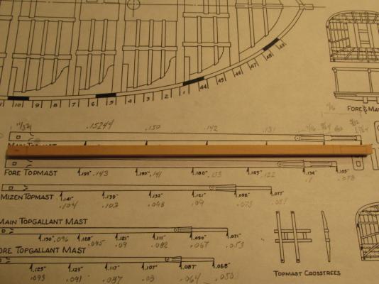
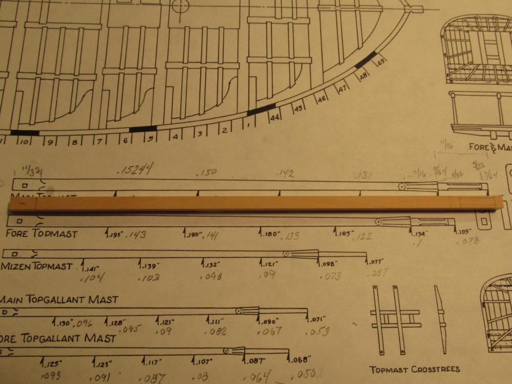
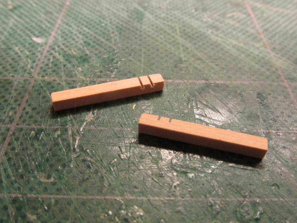
Spare Main Topsail Mast
The other spare is the Main Topsail Mast which is a little bit more complicated to make. It starts off as a 6 1/8” piece of 5/32” x 5/32” boxwood. I measured off where all the transitions from square to round to octagon sections were. Hahn’s plans conveniently provide the thicknesses of the mast and yards at multiple key points to get the proper shape. One just has to remember that those numbers are for the original scale of ¼”=1’. Each of the dimensions had to be reduced by 74% to get to the 1:64 scale.
-
TBlack - Thanks for dropping in. Your tip for putting in the eyebolt holes now is a good idea. I'm so used to drilling holes and immediately filling them with something it just never occurred to me to leave the holes open. It's so obvious, I just didn't think to do it.
As for perfection, I never expected it, being relatively new to this aspect of model building. I was just trying to convey to others that although it's not perfect, it's good enough for my purposes and those imperfections will not be noticed by 99% of the people who will actually view the physical model. If anything I want to encourage new builders to try their skills and not be discouraged by errors along the way. For me, the enjoyment is the journey of the build, the model is just the trophy of the journey.
-
Spare Main Topsail Yard and Main Topsail Mast
The Practicum’s next step is the Ship’s boat and then the spare Main Topsail yard and Main Topsail mast. I’m reversing the order and building the spares first. The boat has to be mounted on the spares so I might as well make them first.
These are my first ever yard and mast constructions, so bear with me. Luckily any mistakes I make will probably be hidden under the ship’s boat.
CAUTION:
Because the spares are obviously duplicate pieces that have to be made again for the model, Mr. Hunt copied pasted the instructions from Chapter 1 of Rigging of the Rattlesnake into Chapter 9 of Modeling the Rattlesnake. Also since the steps required to make one mast and its yards are duplicated to make the other two, he states that most everything is the same except for the dimensions. All fine and good except that all of the detailed instructions for the yards and mast are for the Foremast. When he copied those instructions into Chapter 9 he didn’t alter the dimensions for the spares which are for the Main mast.
The builder must ignore the dimensions given in Chapter 9 for the spares. They are for the Foremast topsail yard and fore topsail mast. The Builder must take off his own dimensions from Hahn’s plans.
It took me a while to figure this out. Luckily I didn't cut much material before I realized something was amiss.
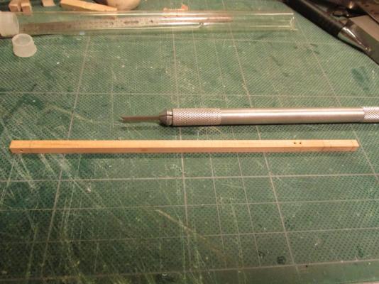
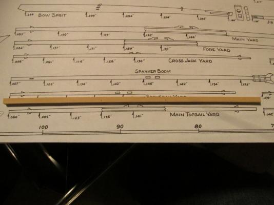
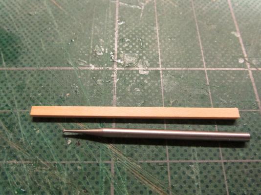
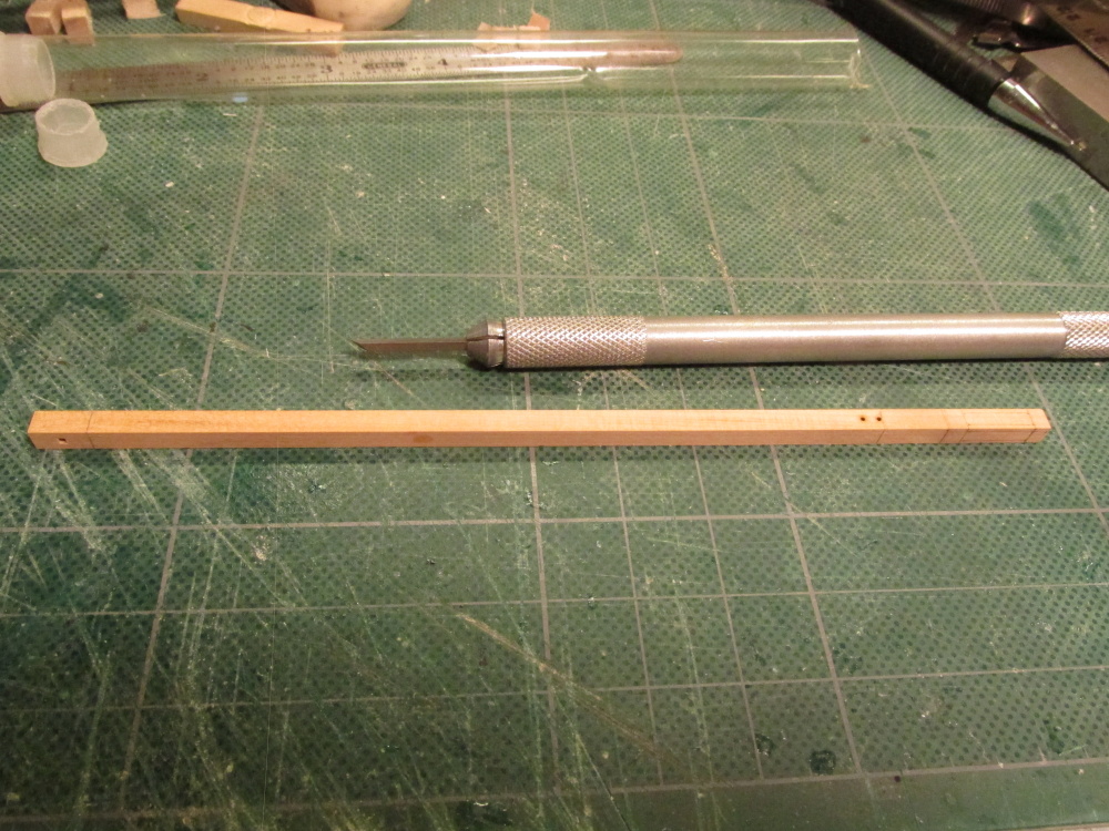
Spare Main Topsail Yard
Of the two spares, the topsail yard looked easier to create. Staring with a 6” piece of 1/8” x 1/8” boxwood, I rounded and tapered the ends to length as indicated on Hahn’s plans. Interesting enough, neither the Mamoli plans nor the Model Shipways plans provided separate drawings or dimensions for the mast sections or yards. The center of the yard is eight sided. This looked easy enough to do, just trim off the four corners to make eight. Not so, I had a lot of difficultly maintaining an even cut.
If anyone knows a simple yet effective way to precisely cut a square cross section into an octagon, I would love to hear about it. I've got a bunch more carving to do soon.
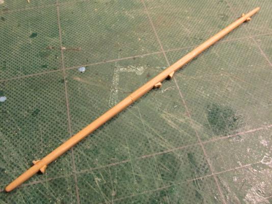
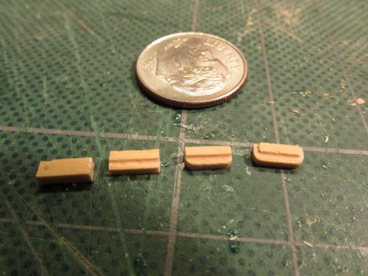
The cleats were made from 1/16” boxwood. The Practicum did not state to add them, but because of other Practicum omissions I've documented, I couldn't be certain they weren't supposed to be there or not. I just don’t how complete the spares were built when stored on board ship.


-
Sr. Old Salt - This model was built using Robert Hunt's Practicum with the expressed intention that it would NOT be painted. That is why different colored woods were used. That being said, some paint was used primarily for the black color. Ideally I would have used Ebony wood in these areas but my supplemental wood package did not come with any. That may have been a blessing as I have read that Ebony is very hard and difficult to work with and the wood dust is slightly toxic.
I'm no expert on paints so I can't tell you off the top of my head whether to use diluted paint, stain, or dye acrylic or otherwise. If it were me, I would try out some test strips and see what happens.
If anyone out there knows more about this, please jump in.
-
Thanks Martin, I would not have found this section in a timely manner when working on the bowsprit in the near future.
I was wondering why he didn't mention the boomkin, he did only it looks like it was an after thought in the context of things. He states:
The boomkin is made from a piece of 1/16" boxwood cut to a length of about 2". It fits at an angle against the stem on each side just under the bowsprit and rests on the headrail. It is angled outward and slightly downward and typically there would have been an iron plat over the boomkin at the head rail to hold it in place.I must assume the "iron plat" is a typo and he meant "iron plate" because I could find a definition for "plat" that made any sense. -
I had thought about the eyebolts and elected not to install them at this time because I thought a block or something would be attached to them. I reasoned that it would be easier to seize a line or add a block to the eyebolts off-ship and then install the complete component at once like I did for the cannon rigging. I would install eyebolts that are not used (say for use with the running rigging) now if I only knew which ones they were.
-
I went back over your log and I found an image where you drilled the bumkin hole. Now I understand what you did. It works for me. Oh, and I will remember to use the...um, colorful language to give some authenticity. Thanks again.
-
Thanks for the feed back Martin. I have all but two of the sources you quoted and one of those, i just ordered last week (Lee). The other, Antscherl, will have to wait. If I get one of his, I'll want all and they ain't cheap. Of the ones I do have, I had looked at before and if they only show the base of the bumkin where it meets the stem. They don't explain the mechanics of how it is attached. So I guess your method is as good as any and I'll follow suit when the time comes, unless I learn something new by that time.
-
I've also have been curious about the bumkins when someone told me not to forget them. Forget them, I didn't even know they existed! So I researched them a bit and at least for the Rattlesnake, I still don't know how they are attached to the stem on the actual ship. Is there a notch they slid into? are they tied or bolted somehow? On the model, most likely they are just glued in place.
Once I've completed the ship's boat on my model, I will have entered into a new phase of my build, the rigging and the bowsprit will be the first thing I tackle. So any info will greatly be appreciated.
-
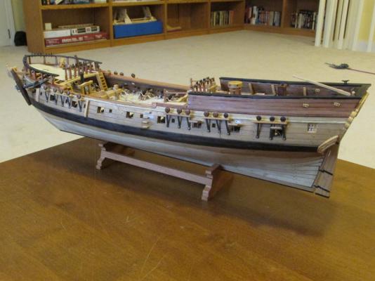
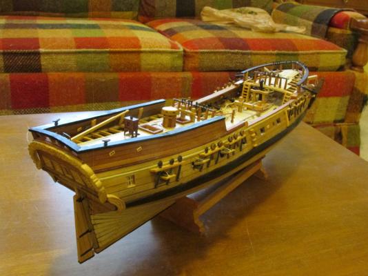
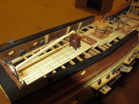
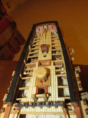
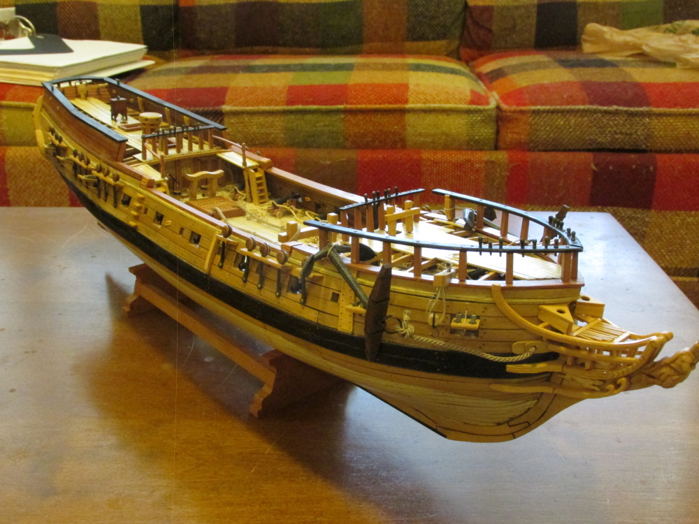
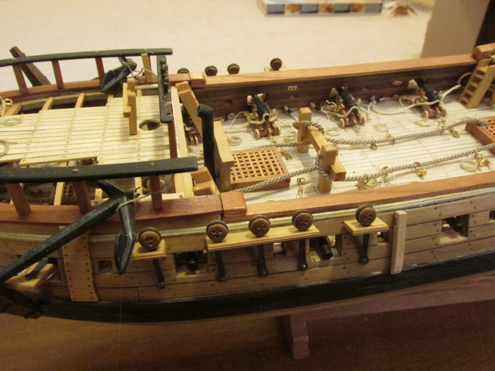
At this point, according to the Practicum, the hull is complete. What is left in Chapter nine of the Practicum to complete is the ship’s boat and the spare masts it rests on; and maybe a tweak or two here and there. Here are a couple of parting shots.
Well, it not perfect. I would have been very surprised if it was but it will have to do.

- wallyinstittsville, MEDDO, CiscoH and 1 other
-
 4
4
-
Pins were then added for added strength when attaching to the side of the hull

-
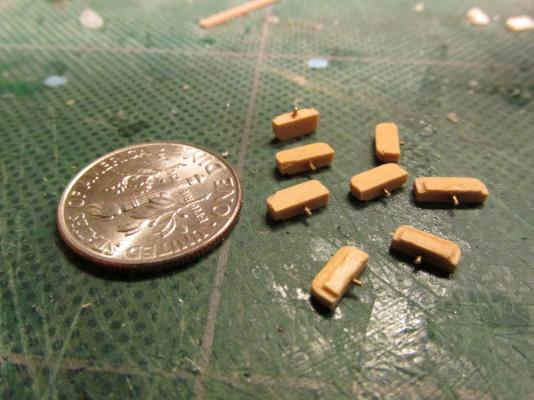
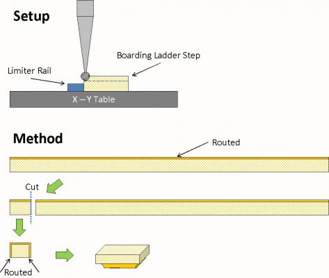
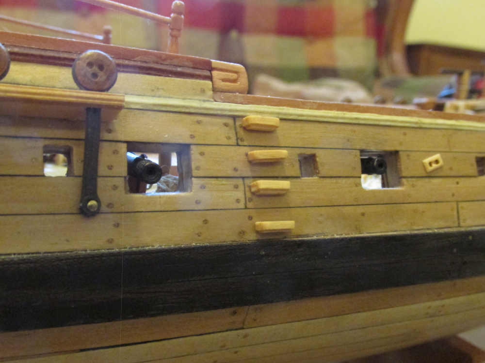
Boarding Ladders
Surprisingly (or not) the Practicum also does not address the boarding ladder, those little steps on the outside of the hull. Mamoli does have an illustration as to how to construct them but I didn’t like the looks of it when I reviewed how other models made theirs. they were to be made with stacked upside down L-shaped channels. So to put it into technical terms, I winged it.
Based on the picture of the steps I “guestimated” their dimensions. The steps are not simply slabs of wood stuck to the side of the hull. They appear to be either two layers of wood, one smaller than the other, or one thick piece carved.
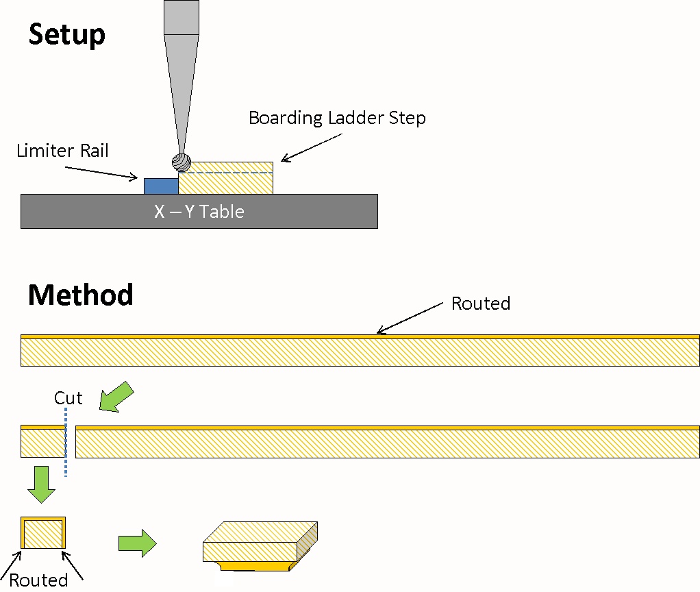
Because of the size of the step pieces, I chose to make each out of one piece of wood. I converted my rotary drill into a pseudo router again using a dentist sized ball burr tip as my cutter. A piece of 1/16” x 3/32” boxwood about 2” long was placed into my pseudo router to cut an inverted rounded corner along the whole length of wood strip. Then eight ¼” pieces were cut, four steps for each side of the model. The new two edges of each piece were then “routed” leaving the fourth side untouched.
-
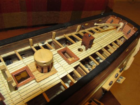
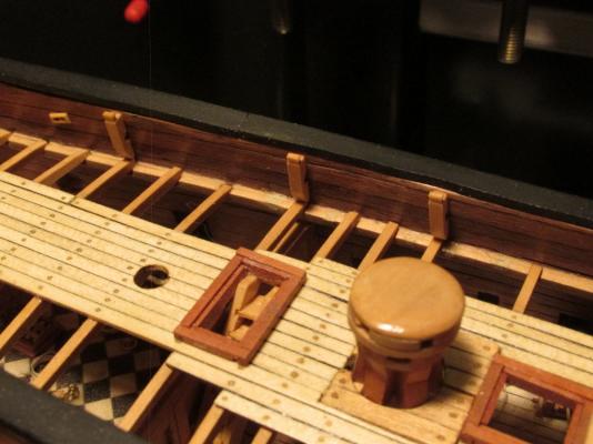
Miscellaneous Stuff
It was time to install three more items to the deck, two of which I had previous fabricated. First the tiller was added to the rudder post and the binnacle was glued to the deck. The third item, the “iron horse” was not addressed in the Practicum. This piece is nothing more than an upside down square shaped “U” wire structure behind the rudder post. Seemed simple enough, but because of the problems I encountered earlier with the transom and quarter deck, I had little room for its installation. My rudder post was practically against the transom. So being technically minded and handy with the tools, I fudged it, artistic license…so sue me. The kit called for brass wire, but that is very soft and therefore deforms very easily. I chose to use music (piano) wire. It’s dark in color and very stiff. My “horse” had to go above the rudder post for clearance due space considerations I mentioned earlier. As a result, mine looks a bit tall and narrow as opposed shorter which would make it look squatter.
-
Igor - I understand, that was my intention. They ended up looking like they do because they were based on the measurement from Hahn's plans which my model pretty much approximates. It should be an exact match but somehow it didn't work out that way. It's easy to draw lines on an image to get the exact angle but I wasn't quite certain how to do it with accuracy on the model itself. I suppose I will have to adjust them in the future when I know better where the lines will actually be. Thanks for your insight.
-
All of this rigging stuff is new to me so I am watching you and Blue Ensign closely. I am getting very close to finishing my Rattlesnake hull and will have to tackle this phase of the build soon. My apprehension grows daily. But like all things, I will take it one step at a time and hope I don't screw it up too badly.
-
The Byrnes saw is a great piece of precision and workmanship. I could not have done many of the things I did without that saw. I also have his dimensional sander and draw plate.
I met Jim and his wife at the Nautical Research Guild convention in Charleston SC this past October and they are great people as well. He allowed me to buy an accessory to the saw with no money provided I went online and ordered it when I got home. And because I got it from him directly at the convention, he made sure to deduct the automatic charge for shipping. He backs up his products.
-
The easy part is gluing them into place. Note two of the kevels are attached to aft rail post where the anchor is tied. The anchor had to be re-tied after the kevel was attached.

-
A chesstree is essentially the same as a kevel except it is installed on the outside of the hull and does not have a knighthead.
-
Using a very fine chisel, the wood material between the lower horizontal cuts was carved to look like the side of a wheel when it will glued in place. Care must be taken here because even a slight slip may cause the chisel to slice through the tiny piece of wood between the cuts.

- Martin W, sport29652 and KenW
-
3
-
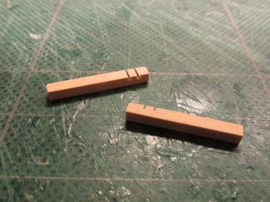
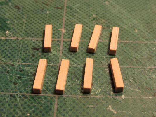
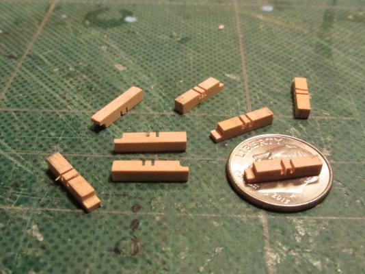
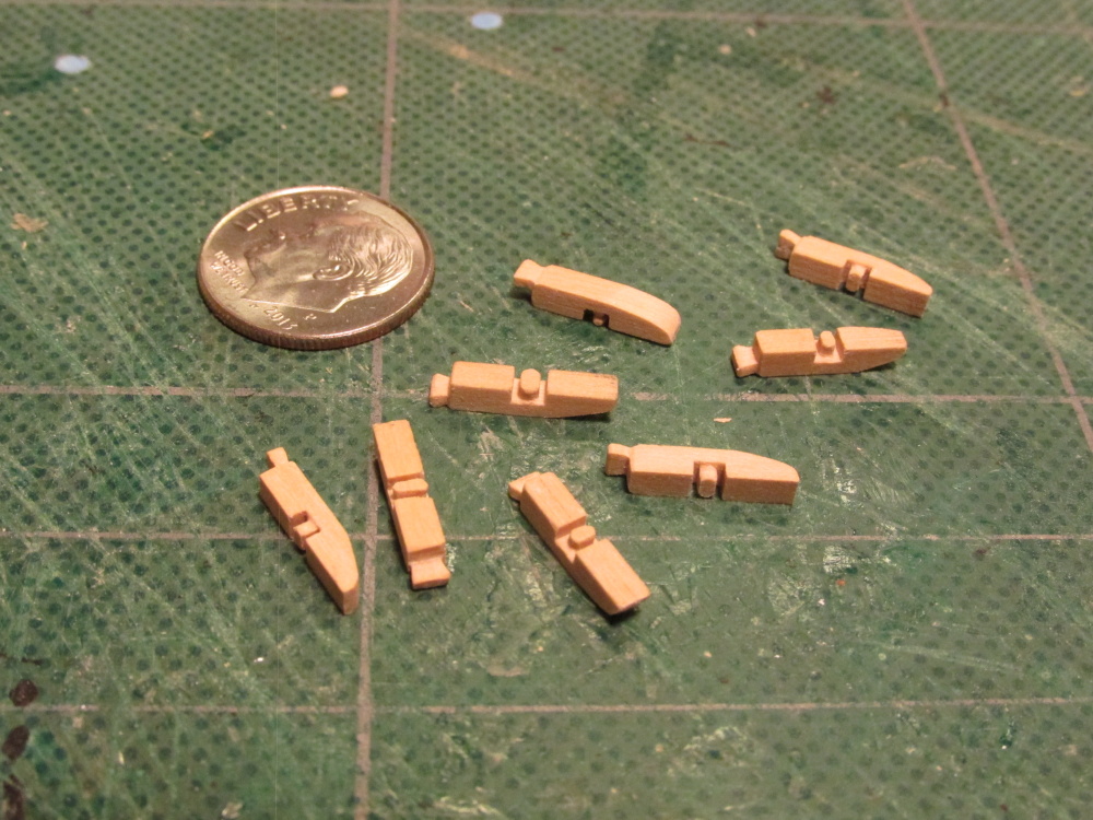
Kevels and Chesstrees
A kevel is basically a post with a sheave in it. The Practicum calls for eight 3/32” square boxwood ½” long pieces. Once more, like the hull sheaves, Mr. Hunt uses one hole for the sheave. I elected to follow the Mamoli plan which shows two. Actually it shows a representation of pulley wheel as well. Because the side that is to be glued to the inside of the hull is exposed during fabrication, it is possible to create a pseudo wheel which I did. Using my Byrnes saw, I made three 3/64” deep cuts across the side and one more across the top to create a notch for the knighthead. It looks like the knighthead is used to tie off and hang excess line.
-
Oh, I like your idea using the Xacto blades for scrapers which allows you the use of a handle! (I had been using a razor blade) Cutting the metal scraper was easy; cutting the metal scraper to the exact profile and proper width I found difficult. Your moldings came out looking real good.
I'm not clear how you are making the hinges out of rings so I guess I will have to be patient and just wait to see what you do next.
-
The names of scratch builders that come to my mind are Harold Hahn (of course), Raul Guzman Jr., and William E. Hitchcock,
-
At least I learned that they are vertical planks and not horizontalNow you've got me confused. The bill board is made of horizontal planks to create a sweeping curved vertical protective wooden plate to protect against the anchor.
What vertical planks are you referring to?


Rattlesnake by JSGerson - FINISHED - Mamoli - 1:64 - Using Robert Hunt’s practicum
in - Kit build logs for subjects built from 1751 - 1800
Posted · Edited by JSGerson
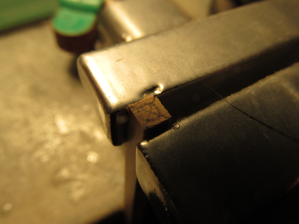
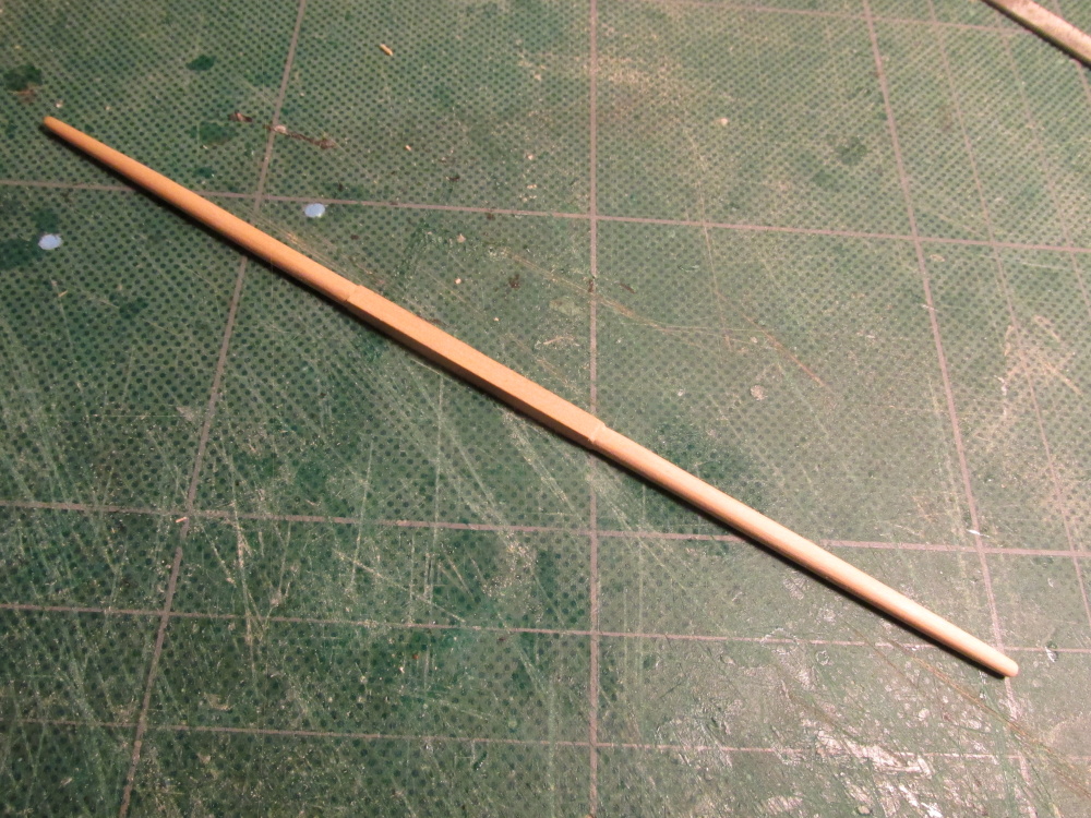
Using my newly constructed V-block jig, the spare mast was cut, carved, filed, and sanded to shape.