JSGerson
-
Posts
2,646 -
Joined
-
Last visited
Content Type
Profiles
Forums
Gallery
Events
Everything posted by JSGerson
-
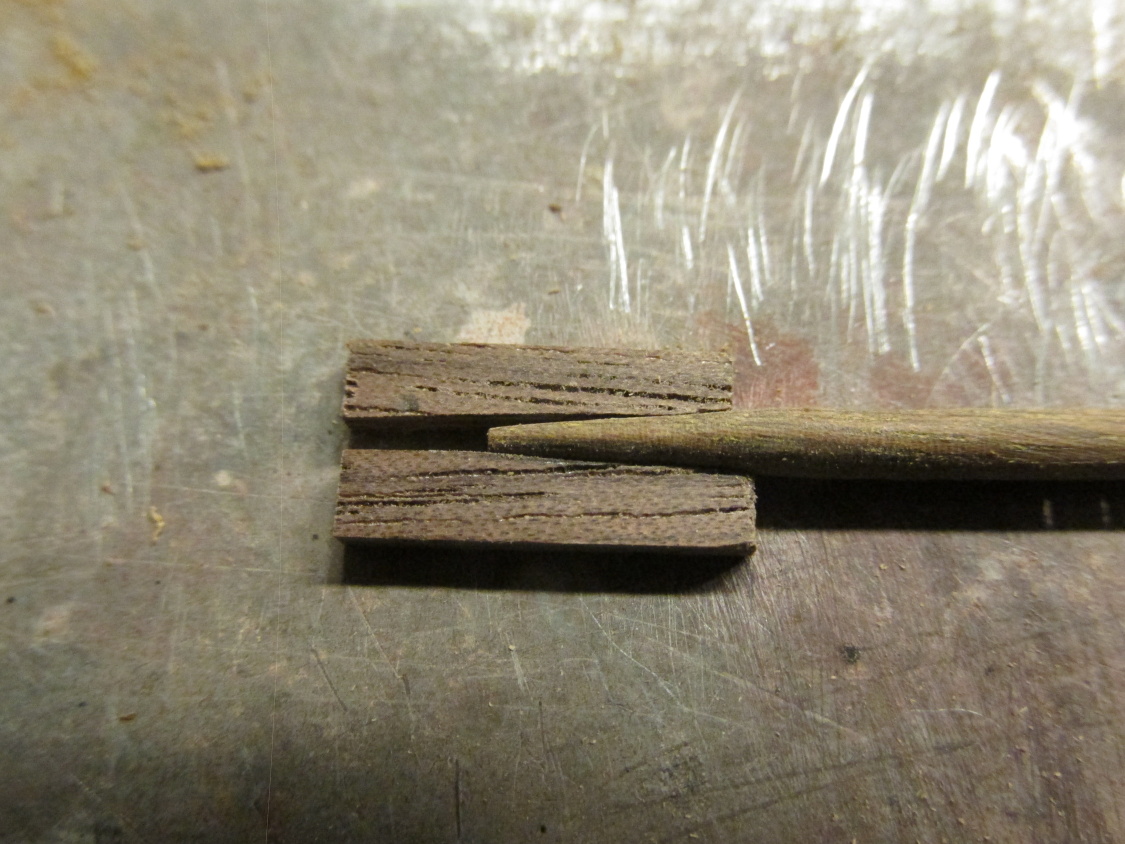
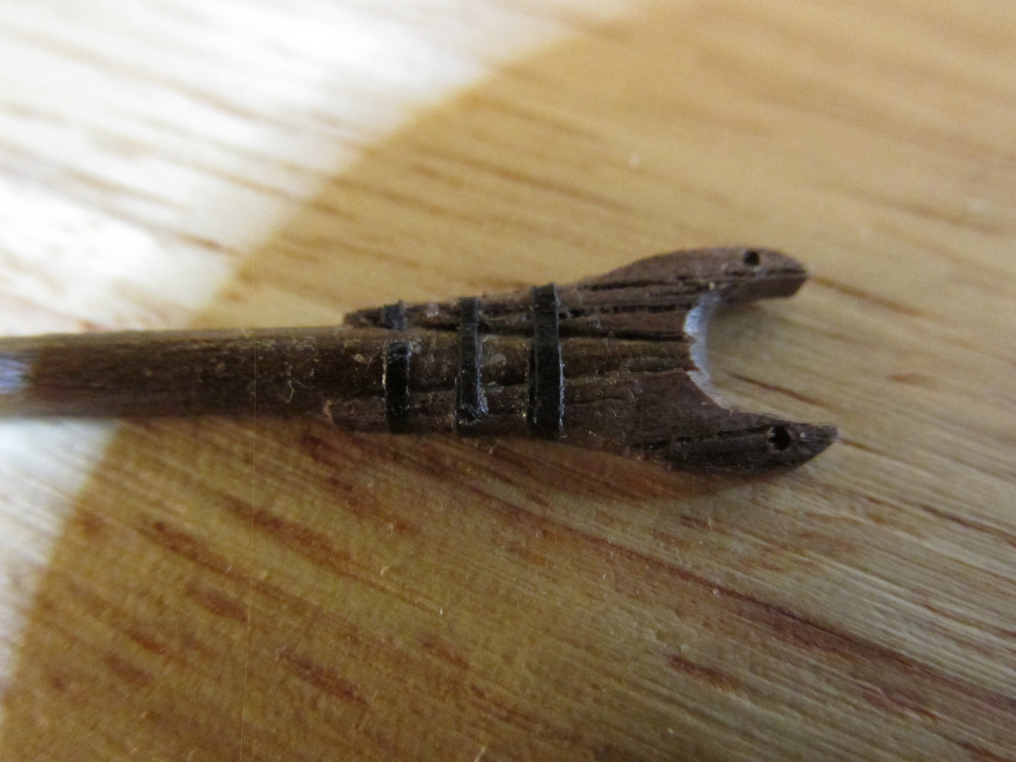
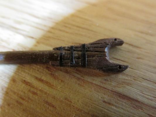
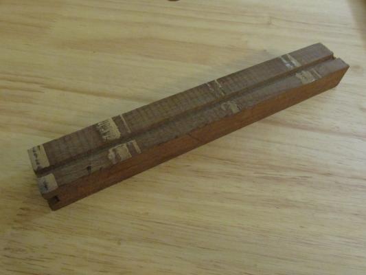
 I started with the Boom and Graff because their jaws looked interesting. The Mamoli kit provided cast metal jaws but I had gone this far with fabricating my own parts, I wasn’t about to stop making stuff here. The jaws were constructed from a couple of pieces of walnut tapered slightly to match the ends of the boom/gaff. Once the white glue set overnight to make sure I had a real solid connection, they were carved to match the drawings on Hahn’s plans. The Practicum stated that Mr. Hunt used lead tape for the three straps that went around jaws. I didn’t have any so I used narrow paper strips colored black using a Sharpie pen. Holes were drilled through the tips of the jaws for the parrals which will be constructed and installed a bit later.
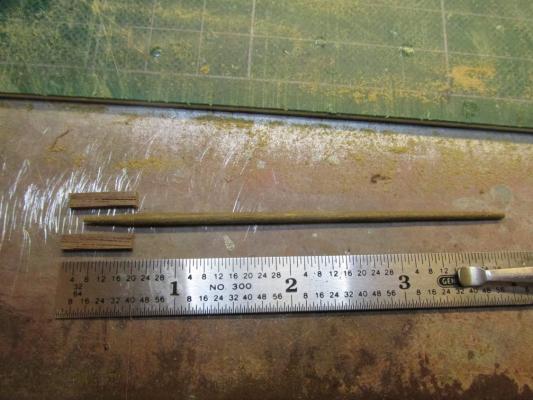

- 974 replies
-
- 7
-

-
- rattlesnake
- mamoli
- (and 1 more)
-
Thanks for the compliment but it is undeserved. I got it from reading other build logs. Isn't this site wonderful?!
- 974 replies
-
- 2
-
-
- rattlesnake
- mamoli
- (and 1 more)
-
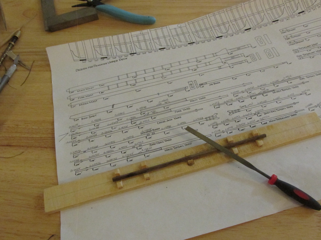
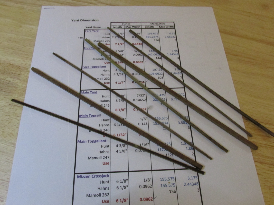
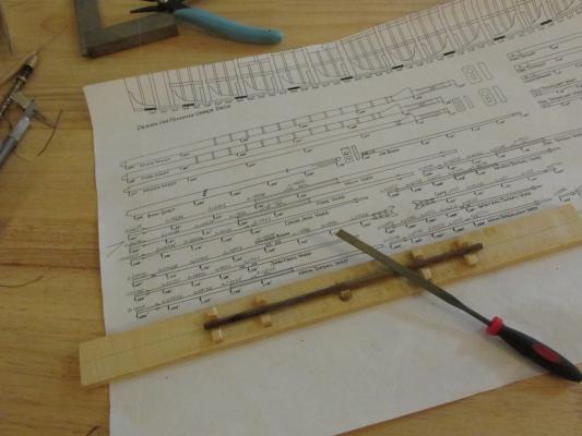
As mentioned earlier, I used the Hahn yard diameter dimensions notated at regular intervals along the length of the yards and booms on his plans. Because Hahn’s plans were drawn at ¼ scale or1:48 the numerical dimensions were reduced by 74% to get them to 3/16 scale or 1:64 of the kit. You might see my hand written notations above Hahn’s in the second image below. All the yards and booms were made using the simple jig I used before on the masts to hold the square cut pieces so than the corner edges could be trimmed and rounded or left alone as needed. The only tool used was a file. I am not that skilled in using a plane or other bladed tool to trim the wood on these slender and delicate pieces. I can control a file a lot easier because it trims off a lot less material at a time. All the wooded pieces that remain to be constructed and added to the yards and booms are the various chocks, sling cleats, and jaws. The rest is all rigging…as far as I know.
- 974 replies
-
- 6
-
-
- rattlesnake
- mamoli
- (and 1 more)
-
I found another video on ebonizing wood, This gentleman shows three methods: The vinegar and steel wool method previously described in the first video Leather stain Archive India Ink (Specifies two brands only) Long story short, he shoots down the vinegar and steel wool as messy, smelly, expensive, time consuming, and highly inconsistent; the leather stain is OK; but he really recommends the India Ink. https://www.youtube.com/watch?v=-0E7E6uSPJY It's worth watching as he details how teach method works and gives the pros and cons of each.
-
Thanks Bob, I did see that photo before but I never noticed the pulley.
- 277 replies
-
- 3
-
-
- model shipways
- 18th century longboat
- (and 1 more)
-
All I can say is, you won't know how well you can carve until you try. I NEVER carved before I attempted the Rattlesnake decorations. You've got nothing to lose in the attempt. You can always go back to what you originally planned if it doesn't work out. Jonathan
- 481 replies
-
- 2
-
-
- rattlesnake
- model shipways
- (and 1 more)
-
You did a beautiful job with the rails. Because my Rattlesnake was my first build, I did not know that the head of the rail was to be used for a line tie off. I would have added the "head piece" as well. I only learned this recently as I was rigging the bow. I totally agree with your decision to install the bowsprit and gammoning at this point. Following Mr. Robert Hunt's practicum almost blindly because I didn't understand how things were interdependent, mine was installed at a latter point when it was much more difficult. May I suggest that you also get your figure head at least prepared and dry fitted if not installed, before the bowsprit installation just so there is no complications down the road. Jonathan
- 481 replies
-
- 1
-
-
- rattlesnake
- model shipways
- (and 1 more)
-
The discussion I saw was on the Amazing Photos Forum and in there Chuck did state that you could post a link to the site where the original photo exists.
- 277 replies
-
- 5
-
-
- model shipways
- 18th century longboat
- (and 1 more)
-
Sport29652 - "close to finishing" what a nice phrase, I wonder what it means? At the rate I work, who knows how long it will take. From the looks of their catalog images, the Micro-Mark and Proxxon milling machines do look very similar so I guess they would have the same abilities as well as faults. But getting one of these machines or something similar (Sherline) is all pipe dreams for now. I'll start to really get serious when I prepare to start the Constitution after I finish the Rattler in the next decade or two. 8-)
- 974 replies
-
- 2
-
-
- rattlesnake
- mamoli
- (and 1 more)
-
There is nothing wrong with my wood lathe other than it's too big for what I need. Nice to know about the Micro-Mark milling machine, I'll cross that one off my list. Just out of curiosity, did you mean the components that came with the machine don't fit, or that standard accessories from other mfgs. don't fit, or maybe both? Jon
- 974 replies
-
- 1
-
-
- rattlesnake
- mamoli
- (and 1 more)
-
When I decided to build the Rattlesnake, I anticipated that I would need a lathe for the masts and yards, so I bought a small wood lathe before I started the kit. I should have waited. I had never used a lathe before and didn't know what I really needed. As it turned out, the small wood lathe (bought from Micro-Mark) was still too big for the delicate work that was required. The lathe has too much torque and can quickly twist and break the small diameter pieces of wood even starting at very slow speeds. My cutting tools leave a lot to be desired as well. Probably I will sell the lathe and get the Proxxon or something like it, but for now it's files and sandpaper. Sigh 8-{ Jon
- 974 replies
-
- 2
-
-
- rattlesnake
- mamoli
- (and 1 more)
-
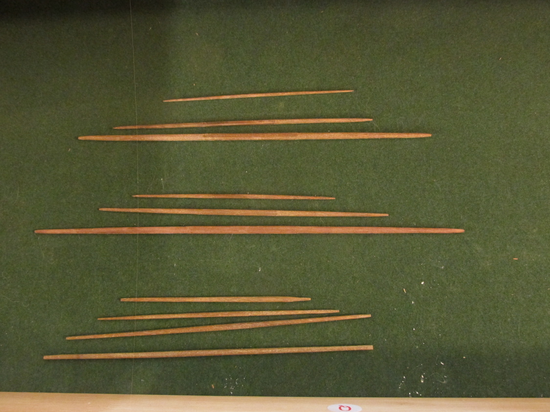
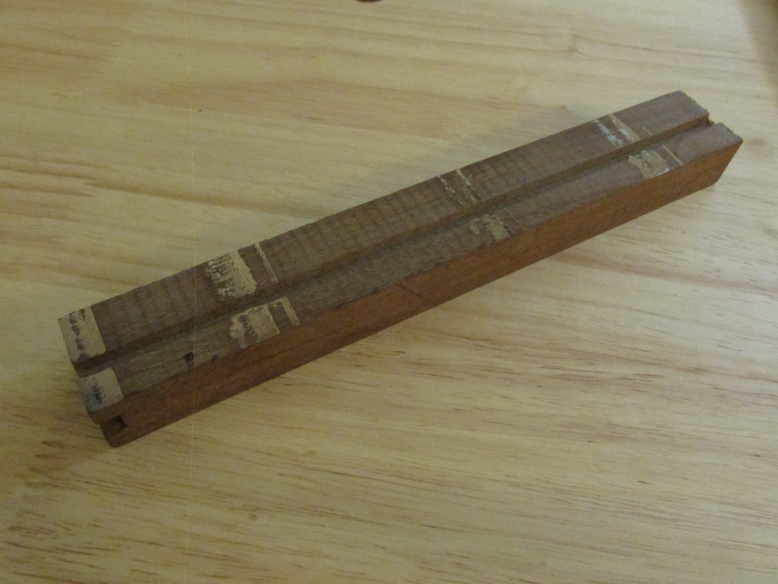
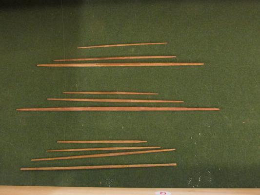
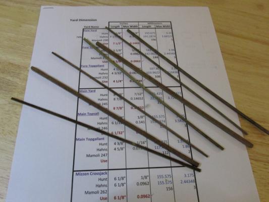
The plan is to mill my own walnut stock for the yards which should be interesting since I have never milled wood before. Ok, what size do I cut the wood to? The Mamoli kit provides overall dimensions and so does the practicum. As near as I can tell, the MS plans do not give numerical dimensions. I guess you just have to do trial and error until the pieces match up with the plans. Hahn’s plans also provided numerical diameter dimensions along the length of the yards to give the yard its proper shape. And just like the old proverb, “A man with one watch knows what time it is, but a man with more than one watch does not,” I compared the yard dimensions of Hunt, Hahn, and Mamoli. You guessed it, nothing completely matched. Some of the dimensions varied as much as 3 mm. Because Hahn provides the interim diameter dimensions along the length of the yards and I followed his dimensions for the masts, I decided to continue using his figures. They appeared to create a finer yard than Mamoli’s and some of his dimensions did actually match with the practicum. The chunk of walnut could make all of the yards except for the main yard, it was too short. For that I would need to cut the board. The Byrnes Saw made the mill work easy. Here is an image of the stock pieces I milled for the yards out of the furniture chunk. I had yet to tackle the big board. Now for the hard part, shaping and making the yards.
- 974 replies
-
- 6
-
-
- rattlesnake
- mamoli
- (and 1 more)
-
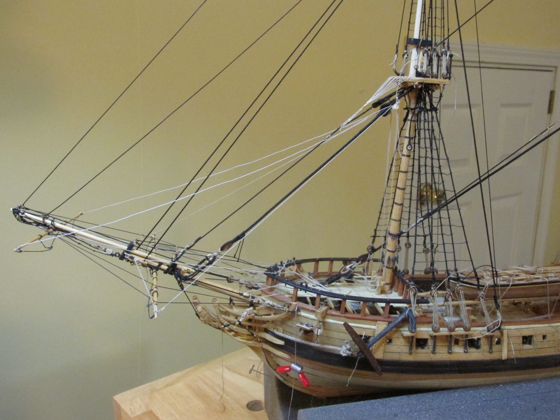
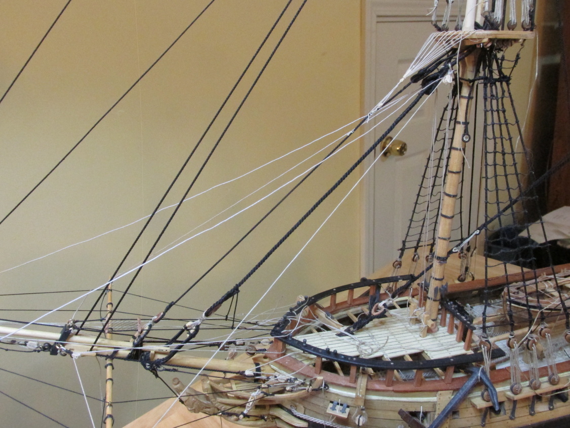
The Yards The time has finally come for the construction and installation of the yards. Continuing to read David Antschrel, he stated that “the yards are usually blackened.” I did not know this. I went back and looked at all of the pictures of ship models I had and lo and behold, most of them had black yards. It was too late to make the yards on my bowsprit black, but I did notice some of those models with black yards had light colored yards on their bowsprit. So I guess I’m alright. Neither the Mamoli kit, nor the practicum addressed this. It may be buried somewhere in the MS plans but I did not bother to look. Since my model is colored for the most part through the use of different woods, I wanted my yards to be made of dark wood and not painted if I could help it. Neither my kit nor the supplemental wood that I purchased for the kit bashing way back at the beginning of the build had dark wood to make yards. But as it happens, I bought some additional wood from Jeff Hayes when he was closing down HobbyMills and in that package of wood, were 3 x ¼” x 12” walnut boards. I also had a hunka chunka of walnut that I purchase from a furniture repair shop a while back.
- 974 replies
-
- 3
-
-
- rattlesnake
- mamoli
- (and 1 more)
-
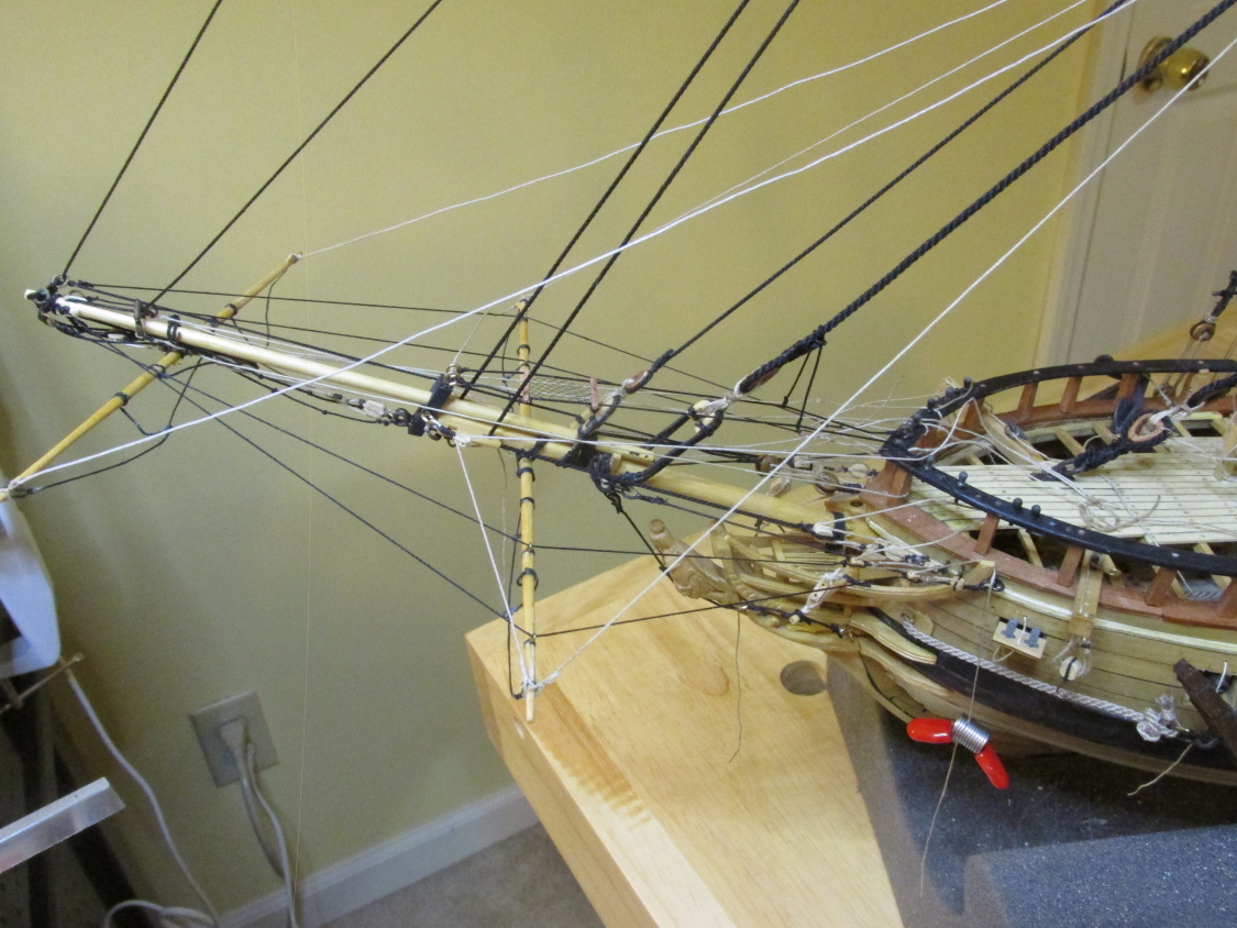
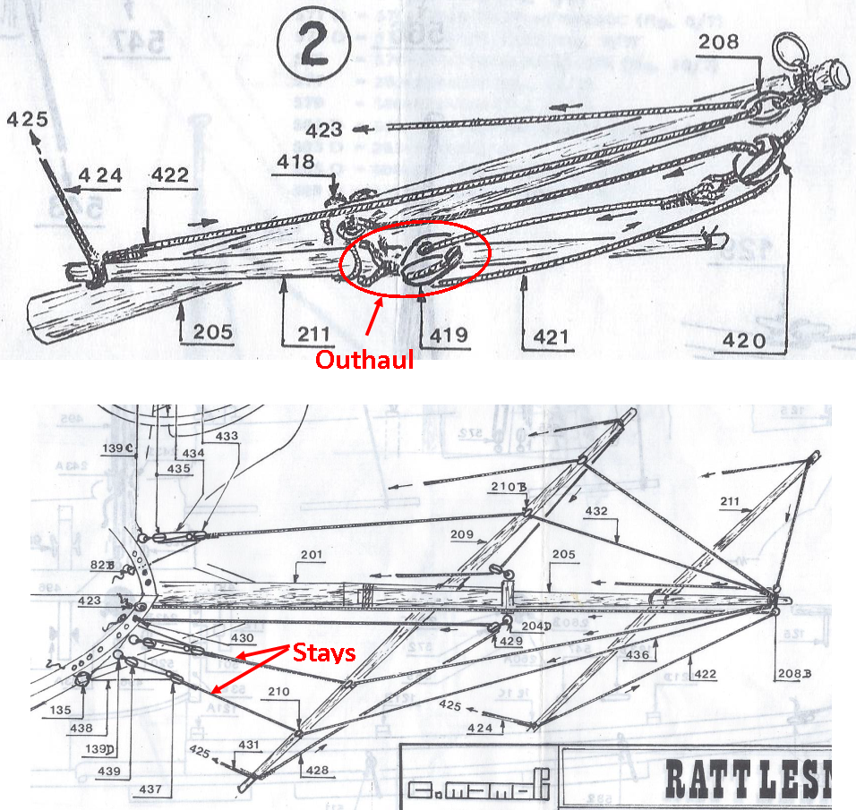
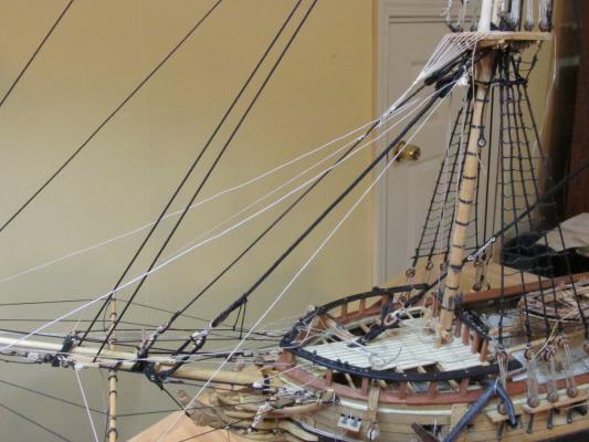
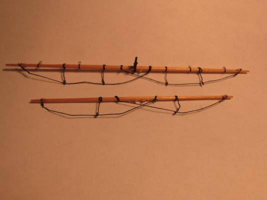
The first thing that happened was the outhaul rigging on the spritsail topsail yard came apart just as I started to rig its blocks. The white glue did not hold and because the threads were all trimmed off, there wasn’t much left to hold on to. Trying to reattach the outhaul while the yard was on the model was a b*tch. I then checked the blocks on the eyelets and they too fell apart when I applied a little tug– all that effort, poof. Screw it, I went back to CA glue which I know holds. I only use a very fine amount. Let’s see what else happened - a couple of eyelets pulled out of the hull and Spritsail yard (used too little glue), I got tangled up in the rigging near the tip of the jib boom and tied things together that should not have, learned to speak that would make a pirate blush (luckily I’m not married so was anyone around to offend and my cat didn’t understand me or maybe just didn’t care), and did I mentioned that I was involved in a fender bender (rear ended at a traffic light – no one hurt, just damage to my car). But I finally got it done save for finalizing the haul line tie-offs.

- 974 replies
-
- 13
-
-
- rattlesnake
- mamoli
- (and 1 more)
-
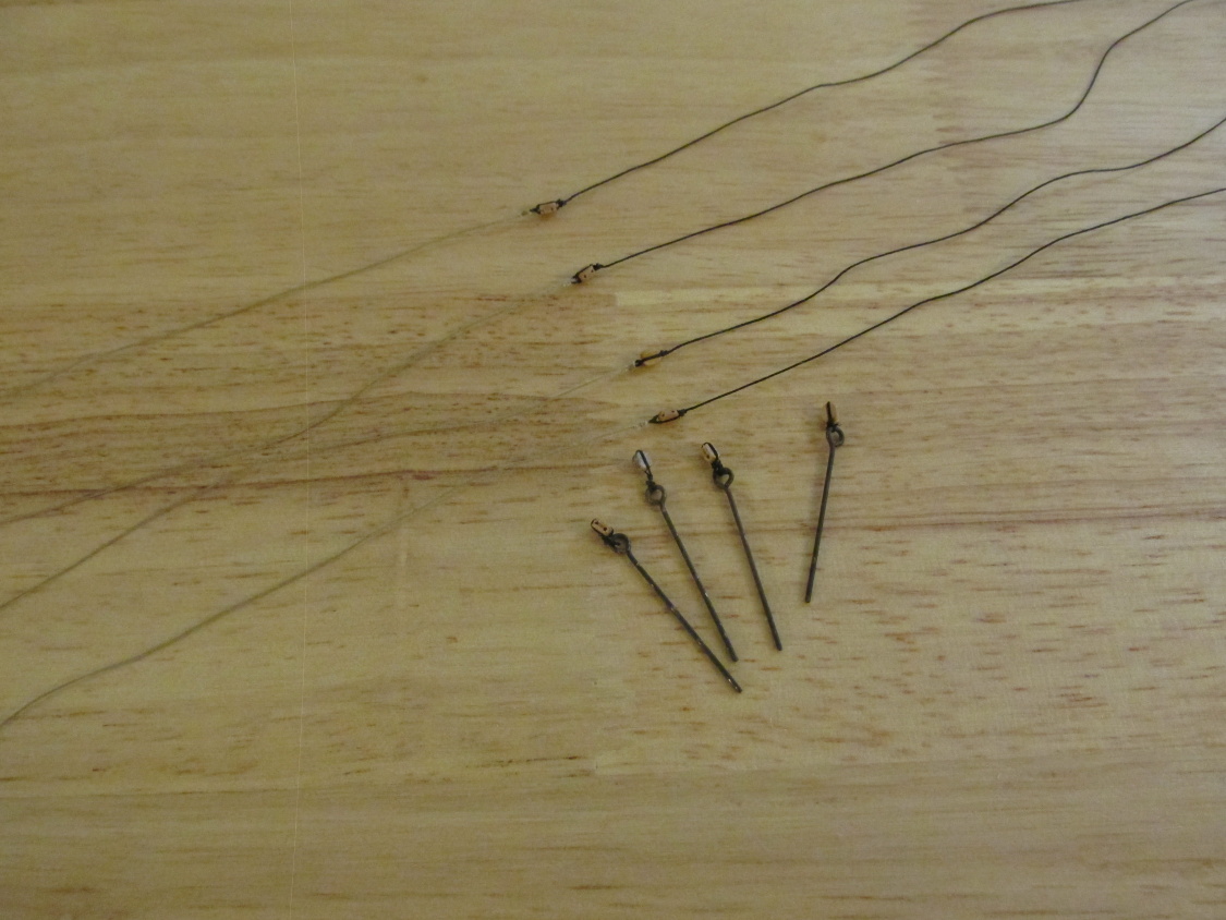
Let me stop here for a moment and talk about glue. I had been using a very fine drop of CA glue on my knots but per a lot of build logs and builders of high respect, the recommendation was to use 1:1 diluted white glue because it didn’t stiffen or discolor the thread. So I started to use the diluted white glue. I made and installed the rigging on the spritsail topsail yard, the blocks attached to eyelets that are to be attached to the hull for the spritsail topsail yard stays, as well as the tackle for the stays. Then the trouble began. I was having difficulty working with the fine rope trying to tie the eyelets to the blocks so that the knots wouldn’t large and/or bulky. These too took multiple tries before I could complete them. OK, I completed all the parts and was ready to assemble the rigging.
- 974 replies
-
- 8
-
-
- rattlesnake
- mamoli
- (and 1 more)
-
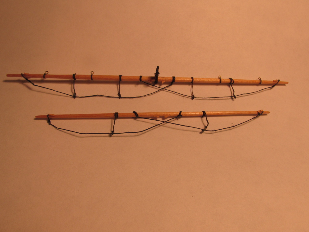
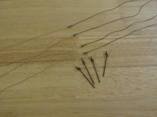
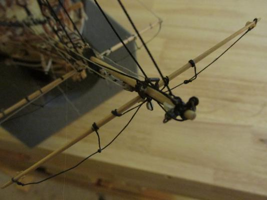
Therefore the first thing to make was that rigging. The sling that held the yard to the jib boom used a finer rope and was smaller and more delicate than the one on the spritsail yard. I must have made at least three slings trying to make the loops small enough and yet still functional and most importantly the proper length. First I made it too long, then too short; the difference was only millimeters. It finally got hung.
- 974 replies
-
- 7
-
-
- rattlesnake
- mamoli
- (and 1 more)
-
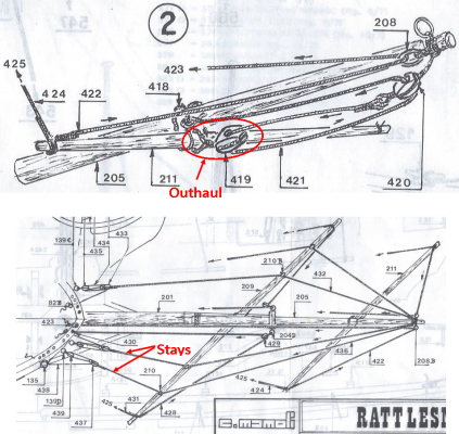
Spritsail Yard Stays and Spritsail Topsail Yard My traveling is done for a while, the Holidays are over, I have no excuses left to explain my lack of progress. It was time to install the spritsail topsail yard. I thought this would be a piece of cake seeing that it was almost a duplicate of the spritsail yard installation. It wasn’t. When I made those yards last year, I added the rigging for the outhaul only to the spritsail yard. The rigging for the spritsail topsail yard outhaul used a block instead of a hook.
- 974 replies
-
- 3
-
-
- rattlesnake
- mamoli
- (and 1 more)
-
You must have a good memory, It's been a looooooong time since I started the Rattlesnake. Your Conny is looking real good. I hope to started mine before the millennium is up. 8-) Jonathan
-
What method did you use to make the mouse?
-
I went looking for your reference and had no luck. And where can I find the full image of the painting they used as justification? The Constitution is next for construction some time in the future and I'm trying to get all my reference together now. Thanks
- 1,354 replies
-
- 1
-
-
- constitution
- model shipways
- (and 1 more)
-
Ken, the carving is a matter of personal taste and pride whether or not anyone else can see it but you and God. I get a lot of praise from my family and friends on my Rattlesnake carvings even though I know it's very rudimentary. It was after all my first ever carvings. They didn't see the fine Bob Hunt example I was following. So, put in what ever detail makes you feel good. Jonathan
- 481 replies
-
- 2
-
-
- rattlesnake
- model shipways
- (and 1 more)
-
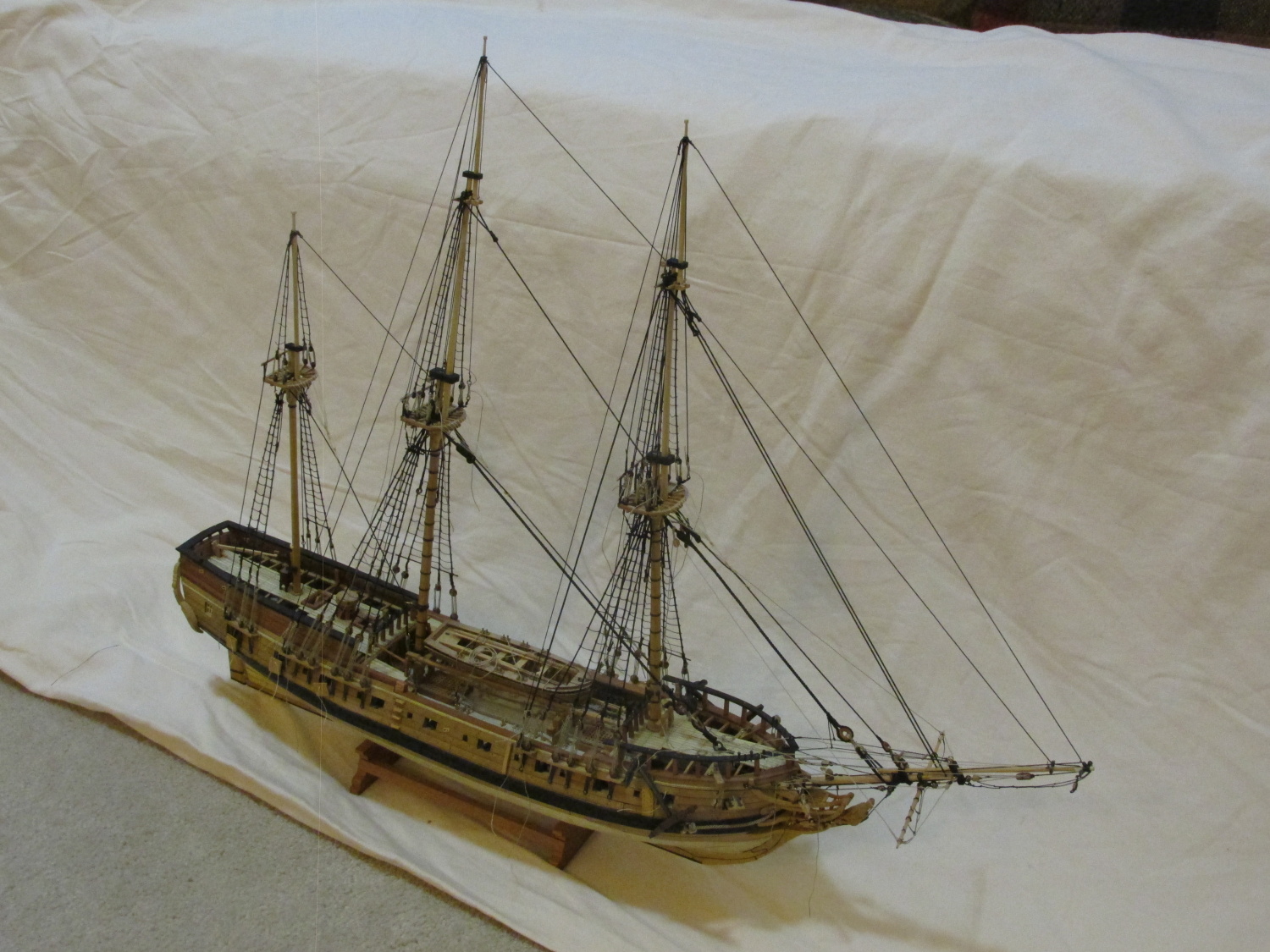
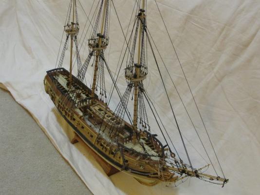
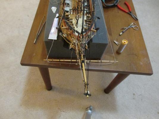
That being said, here is the state of the model as she now stands.

- 974 replies
-
- 14
-
-
- rattlesnake
- mamoli
- (and 1 more)
-
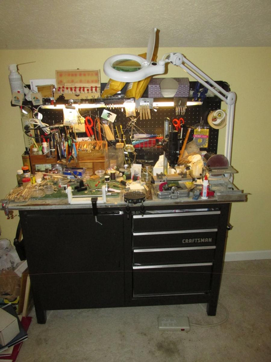
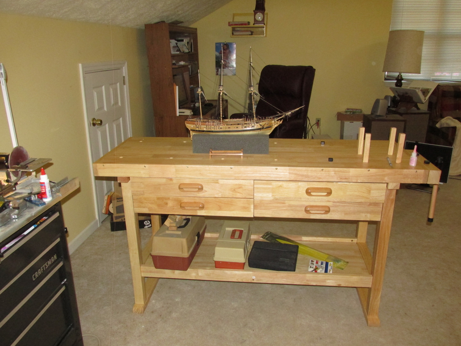
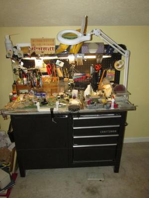
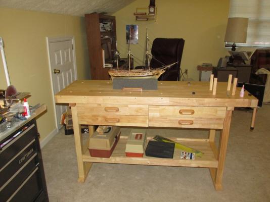
Status My last log entry was posted a few days before Thanksgiving. Then I left for my annual trip to my Sister home in colonial New England where it not uncommon to see signs on homes stating they were built in the early 1700’s. It’s just outside of Hartford CT but very picturesque. Her house is only 35 years old, but that’s another story. Anyways, I spent the week there so no work was done on the model. Last week I returned home and thought I was all set to start work on the Spritsail Topsail Yard when I decided to check the rigging list provided by my Mamoli kit. And low and behold I discovered that I had forgotten to install the main and fore masts Topgallant stays which are very similar to the topmast backstays. So here it is, the beginning of a new week, the stays were constructed and installed, and now I am preparing to visit Mom in Florida (where else) for a week. She’s 97 and she’s got a bunch of “honey do’s” for me. I don’t know how much I’ll get accomplished this week on the model before I leave. There was one other item that also took a day of my time. About 10 years or so ago, I bought a metal work bench. It had a clean metal work surface, drawers, and a peg board to hang tools and stuff. I added the power and lights. It work great and it would still work great today if I didn’t have so much stuff on it now. It’s gotten so bad that I have to clear a small spot very time in order to do anything. The model has to be on the coffee table because there is no room. Fed up, I finally bought a wooden work bench from Harbor Freight (a China store) for $135 - cheap. It weighs about 100 lbs so it’s solid. The instructions to assemble it were easy to follow, all the holes lined up, and all the hardware fit and worked. I couldn’t have asked for more. The two benches were placed in an L-shaped configuration and the work lamp can swing to either bench. This should make things a bit easier, at least until I started accumulating stuff again.
- 974 replies
-
- 4
-
-
- rattlesnake
- mamoli
- (and 1 more)
-
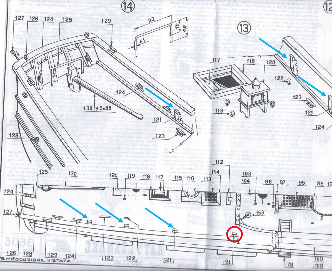
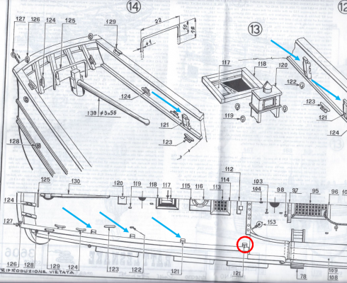
I am building the Mamoli version of the Rattlesnake and am just beginning the running rigging, so your question peaked my immediate interest. According to the MS plans (of which I have a copy) there are only 3 Kevels per side on the Poop deck and none abreast of the main mast. That would be just about impossible with the gang plank at the waist. I looked at the Mamoli plans and at first glance, they confirmed what was shown on the MS plans…except for one sheet (No. 3) which I have reproduced below. I have marked with blue arrows the location of the kevels. The one circled in red is a forth kevel not shown on the other sheets. I believe that is the one you need. I have not installed this one on my model because until now, I didn’t know that it existed or that I even needed it. I hope this helps
- 481 replies
-
- 2
-
-
- rattlesnake
- model shipways
- (and 1 more)
-
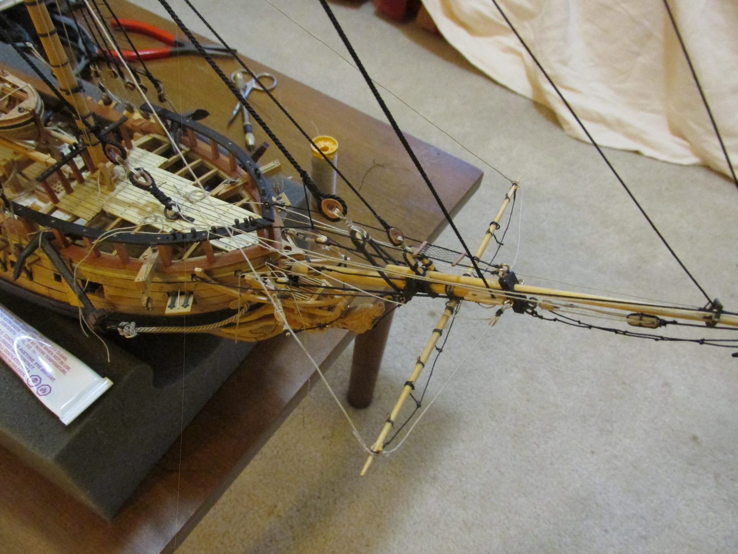
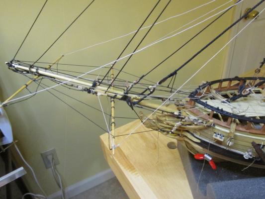
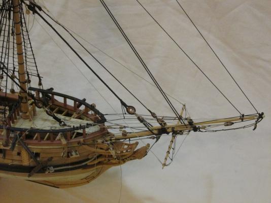
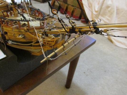
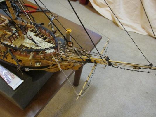
Once the double blocks where installed, the spritsail yard braces and lifts were strung. The braces go from the tips of the yard directly to the pin rail. The lifts, go from the yard tips through a block on the side of the bowsprit cap (previously installed) up through the double block on the forestay and down to and through a sheave in the bitt just forward of the foremast where it’s tied off. At this point none of the lines have been tidied up or finalized. They are still a bit loose.
- 974 replies
-
- 6
-
-
- rattlesnake
- mamoli
- (and 1 more)