


JSGerson
-
Posts
2,482 -
Joined
-
Last visited
Content Type
Profiles
Forums
Gallery
Events
Posts posted by JSGerson
-
-
Just discovered your log today. Thank you for the kudos on the ship's boat. Everything you see on my log I'm experiencing for the first time so beware and read ahead, I make mistakes...lots of them. Hopefully, you won't fall into the same pitfalls I did. Good luck on your build, I look forward to follow it.
Jonathan
-
Main Preventer stay and Foremast shrouds completed

- GuntherMT, KenW, Blue Ensign and 4 others
-
 7
7
-
I didn't actual buy a decal kit Per Se. I just bought a small pkg. of decal paper (for inkjet printer in my case) and a 3 oz spray can of Testors Decal Bonder.
- I first print the image on regular paper so I know where it's going to print and to check for scale
- I then taped a piece of decal paper onto the regular piece of printer paper over where the image printed and run it through the printer again.
- Then I spray the bonder over the printed decal paper and let it dry
- I trim off as much of the excess decal paper as possible
- Dunk the decal in water, apply to the model surface, and adjust the position
- When dry, I apply a coat of Micro Sol Settting Solution for Decals to soften the decal so that it tightly conforms to the surface and it conceals the decal edges
- Finally I apply a clear non-gloss (glossy as applicable) coating (usually polyurithane) to the complete surface, not just the decal, which seals it permanently
- CaptainSteve, GLakie and usedtosail
-
3
-
If you are going to print the ship's name you might want to consider the method I used for my Rattlesnake using homemade decals:
Just remember, you cannot print white lettering! There is no white ink. You must print it as a negative with the background color matching the required color of the model area to receive the lettering. The area to receive the decal must be painted white, The printed white lettering will be transparent on the decal and the white area you paint will show through.
- GLakie, usedtosail and CaptainSteve
-
3
-
JerseyCity - Just a thought, could a clear plastic straw been used instead of the bamboo skewer? You could have painted the inside of the straw to give the "lamps" a transparent lens look or would the wire detailing not work with the flimsy plastic?
- mattsayers148 and GLakie
-
2
-
wq3296 - The practicum does two things, first for those people like me who never built one of these model before, it was a great help. Second, Bob Hunt's practicum is a kit bash. He deviates from the basic model to give more detail and panache.
Jonathan
-
Now is a good time to review my log so you won't commit the same errors I did to the Captain quarters:
Transom Modification - Somehow my transom came up shorten length which had repercussions further on in the build
The short answer is yes you can customize the bench. I didn't follow Bob's directions completely for the bench either due to previous errors and building technique. However, the visibility on the bench will be limited to just a few viewing angles so don't over do it.
Jonathan
-
Sport - Because I have the plans from Mamoli, MSW, Harold Hahn (Robert Hunt) , and the Smithsonian I can see numerous variations. Looking closer at the MSW plans, the "rings" are labeled "thimbles" and the MSW plan shows what a thimble looks like. What it doesn't say is what the material is. As near as I can figure out based on my "google" research, thimbles were made of metal. So according to MSW you are partial correct. Your wooden "bullseye" should be (?) metal but not a ring as shown in Mamoli. The others plans don't specify the material for this item. Were rings used, were bullseyes used, or thimbles? Your choice.
Scott - it was my build log which lamented that Hunt's Rattlesnake Practicum was rushed at the end, but as I have stated numerous time in different log comments, I could not have built my model without his help. I too have most of Practicums. He had a "sale" a few years ago in which he was selling all of his practicums for the price of one. Since I was and am still planning on building the USS Constitution, I needed that practicum so I ended up getting all that he was offering.
When I get to the Futtock Shrouds I will be taking a crack a silver soldering to make the Futtock Plates. Having never done this before we will see how it goes. If unsuccessful, I will probably follow your lead.
Jonathan
-
Just for your info, the Mamoli plans show a brass ring where you used a bullseye. Who's right, I haven't a clue.
-
I knew that back and forth business was the culprit, but I could make such nice tight seizings with my seizing machine. Yeah, I've got a number of various size needle tweezers, forceps, and what nots, but what I really need is a third or possible forth hand (preferably tiny ones) and my feet and toes just don't cut it! My only excuse (and it's not a good one) is this is my first crack at rigging one of these models where I think I know what I doing (debatable) so I have some slack?
-
The way I have been doing the deadeyes was with a paperclip as you described. I'd wrap the shroud around the deadeye and grab the line tight to the deadeye with a strong clip so the deadeye couldn't move. Then I'd remove the shroud from the model making sure not to disturb the clip and attach shroud line to my seizing machine and seize the line in three places above the deadeye. Then shroud would then be returned to the mast and I do the other end. Trying to seize the line while on the model proved to be messy. I couldn't make a nice clean seizures wrapping the line by hand. I was wondering about how a working ship could keep the deadeyes lined up straight and basically you inferred they can't, so I feel better.
-
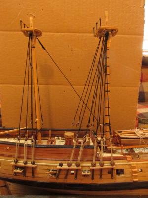
The Main Mast shrouds were next. Getting the deadeyes to line up proved to be troublesome. This may have been the result of my seizing the lines off the model using the sizing machine. Once the deadeye was sized, any adjustments to it were impossible.
There was one other hiccup: if you ever drop a tiny part onto the model deck, finding and retrieving it is just a matter of pure luck. If it falls into one of the stairwells, it’s gone. That part will find a nook or cranny to wedge itself in. You will not get it back; period.
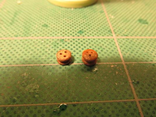
This happened with a deadeye. I saw it drop onto the deck and then it vanished. That was it, poof! Because the kit had a finite amount of deadeyes, losing one and getting a replacement part wasn't an option with Mamoli who is now out of business. I had to make one. Luckily I had a leftover piece of a dowel that was the same diameter as the deadeye. I slice off a piece the same thickness as the deadeye and then drilled the three holes. The first time I tried it, I drilled the holes with a hand drill. That didn’t go so well as one hole angled into another. On my second attempt I was successful when I used my Dremel drill press rig. The piece was then hand filed to its final shape and then stained with Early American Min-wax. It worked. In the picture of the deadeyes below, the original one is on the right and my replacement on the left side.


- CaptainSteve, KenW, Blue Ensign and 1 other
-
4
-
-
I don't know why you were so worried about the clutter. It looks essentially like my work bench!
- mattsayers148, GLakie and 7 Provinces
-
3
-
Actually it is shown on the Model Shipways plans, you just may not have recognized what it was. The instruction booklet does mention the billboard once (that I have found) on Page 23 figure 34. They just didn't give you much to go on. That's one of the reasons that I'm going so slow in my build. I do a lot of reading and comparing what others have done and then I do some wrong and do it over again, once if I'm lucky. 8-).
Even though my model is made by Mamoli, I have the Model Shipway plans and instruction booklet, Harold Hahn's plans, and even the plans for the model that resides at the Smithsonian. No two are alike.
Jonathan G
-
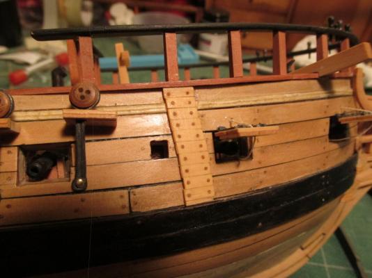
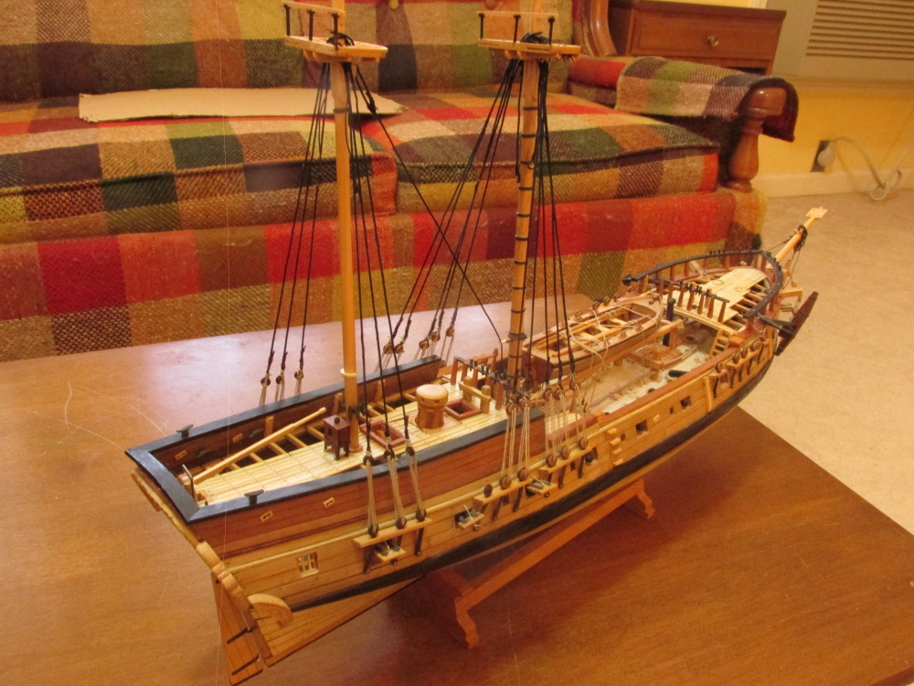
The billboard is at the bow of the ship. It protects the hull were the anchor rubs against it. It's called the billboard because the triangular points on the anchor are called "bills."
As for the side hull stern window decoration, I followed Harold Hahn's plans which were based on the Royal Admiralty original rendering of the ship when they captured her. Those plans don't show any decorations at all, so I didn't put any on. You will find that a lot of Rattler modelers didn't ether. The choice is yours.
-
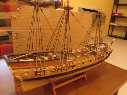
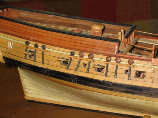
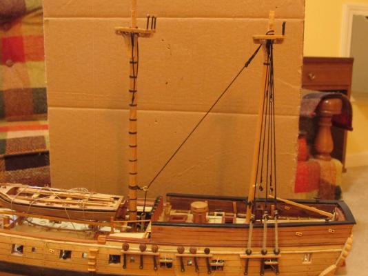
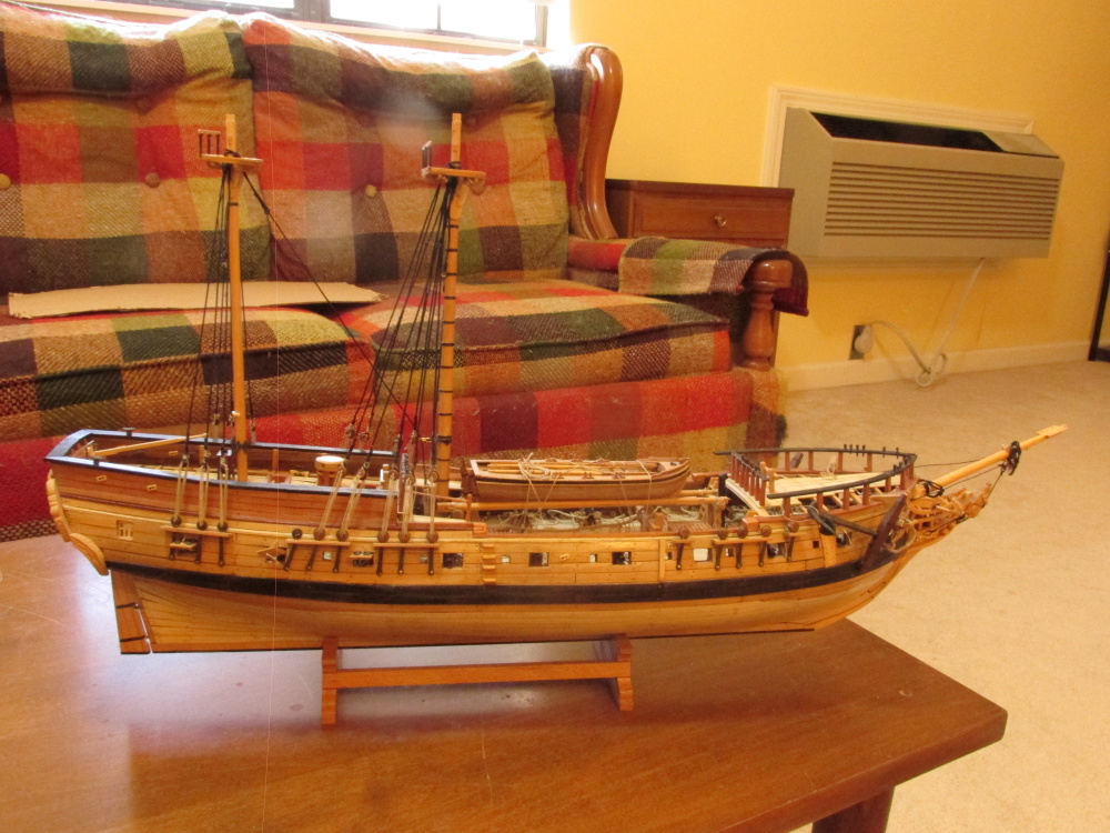
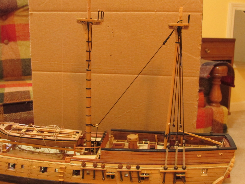
You've made a very nice clean looking model.
Got any close-up images on those deck details? I also noticed that you added the hull ladder. Don't forget to add the billboard. It's easier now than later.
-
-
-
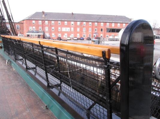
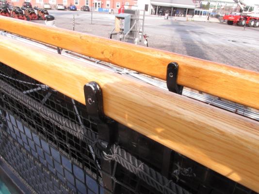
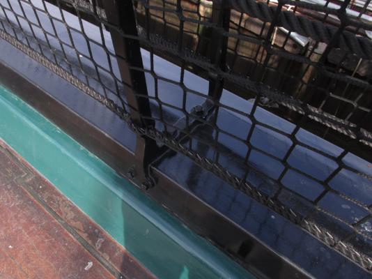
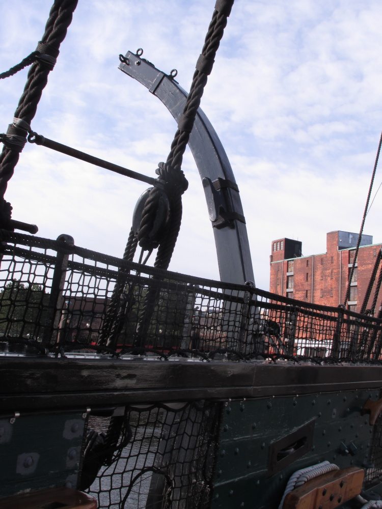
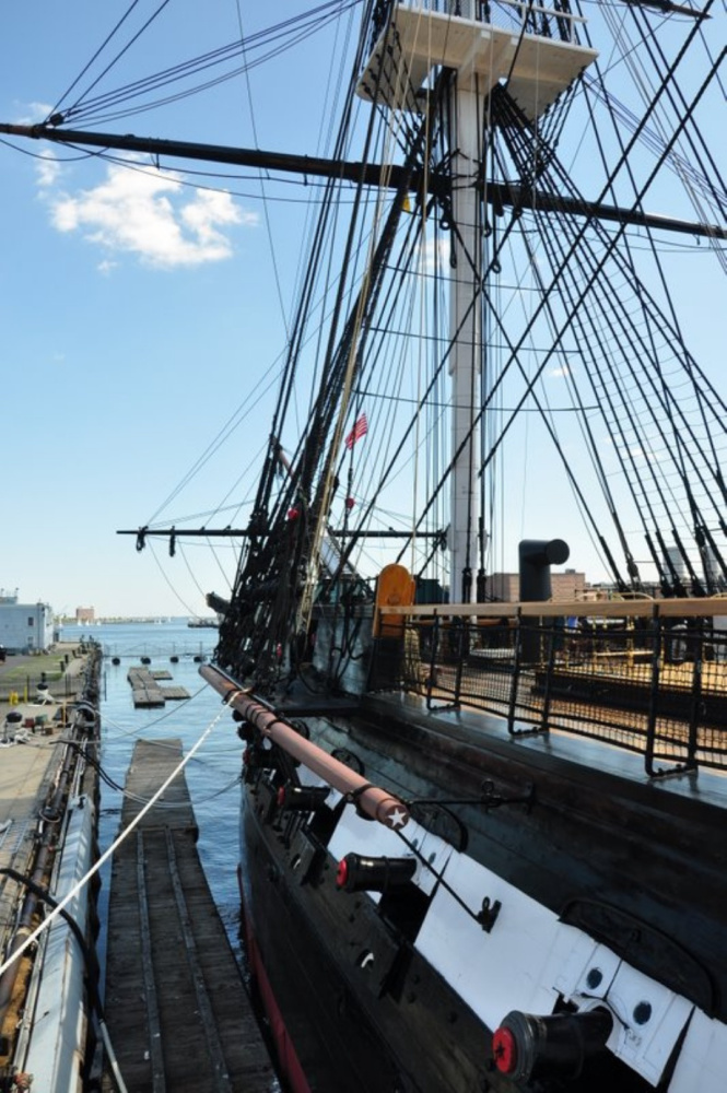
Jay, I recently visited the Constitution last Thanksgiving just as she was being taken apart for her move to dry dock for her next 3 yr renovation. All of her deck guns were removed and well as the yards. However, I just happen to take some close up images of the hammock netting and thought you might need/want another look/see.
Just realized the last image (from the dock) is not mine, I got from the internet somewhere


- dgbot, CaptainSteve, Modeler12 and 2 others
-
5
-
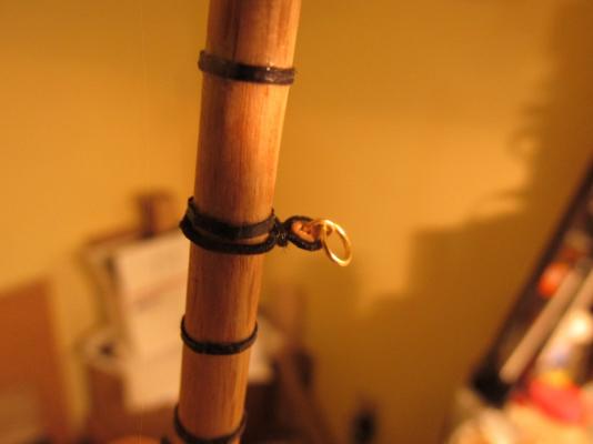
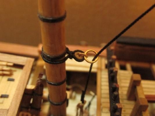
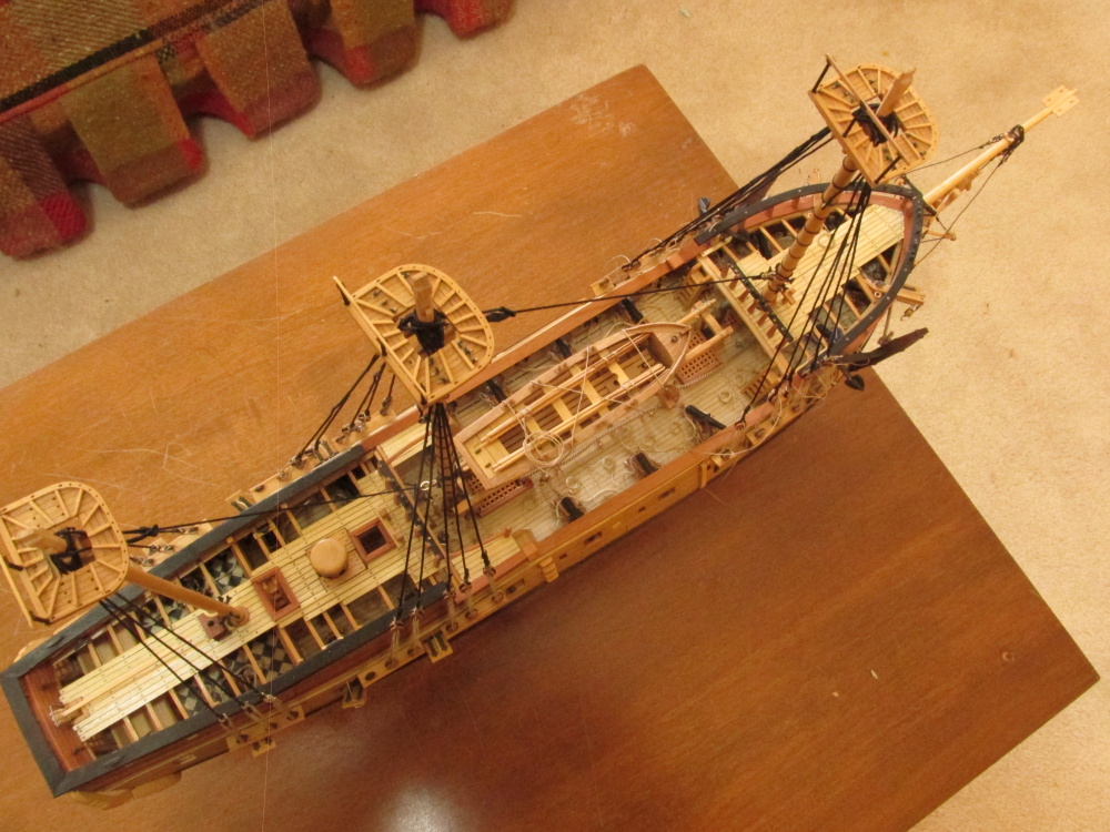
The Main Mast and its mast wedge were set into position and then another ring assembly made of stropped heart, a small ring, and a larger ring were lashed on. This ring assembly guides the Mizzen Stay where it is lashed to the deck rings.
NOTE: Do Not Make This Mistake See Post 727
- GuntherMT, msberkman, Salty Sea Dog and 3 others
-
6
-
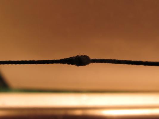
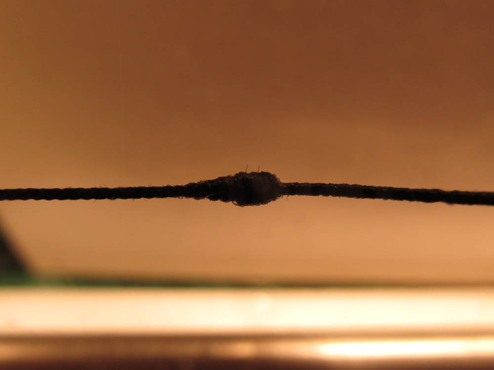
The mouse was built up into cone shape on the sizing machine and held in shape with some CA glue.
- KenW, Salty Sea Dog, CaptainSteve and 2 others
-
5
-
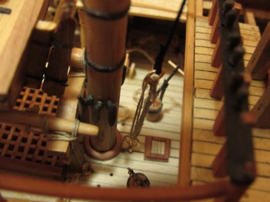
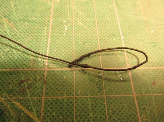
Mizzen Stay
Working from inside to outside, the Mizzen Stay was next and it required a mouse. I saw a number of ways to construct this item. One was making a wooden cone, a pseudo mouse, and staining it black, another was going a step further and sizing the black cone, another method was building up the line with sizing to create the mouse, and final actually weaving a mouse on a jig. Since the stay had to be sized from the mouse all the way to the end loop, and due to the relatively small diameter of the stay and subsequently its mouse, I chose to build up the sizing to create the mouse.
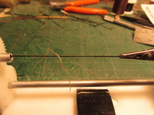
A measurement was taken to determine the location of the mouse and marked on the line with a light piece of thread tied to the appropriate mouse position.
- Salty Sea Dog, KenW and Martin W
-
3
-
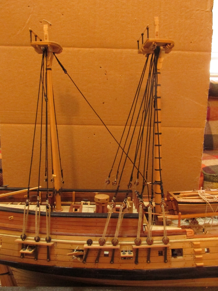
It was brought to my attention that the single shroud (cut-splice) should have been placed in the most aft position. This mistake was not corrected. It would have meant dismantling and re-installing all of the rigging for something that was almost impossible to see.
If you looked closely you may have noticed that the lashings of the shrouds were made with a dark brown thread. This was done for two reasons. First when I tried using black thread on the black shroud, I couldn’t see what I was doing and therefore was doing a lousy job. My eyes are not the greatest. I’ve been wearing glasses since I was seven and now I need tri-focals and a clip-on eye loupe. The second reason was even if I did a good job, nobody would be able to see it. If that was the case why bother? Hence, a slight lighter thread but still dark enough solved both problems. Also, if you have microscopic vision, you may notice that I painted the bitter ends chocolate brown to simulate leather protective caps.


Rattlesnake by KenW - FINISHED - Model Shipways - Scale 1:64 - American Privateer
in - Kit build logs for subjects built from 1751 - 1800
Posted
Just because I'm ahead of you doesn't mean you can't ask questions. Ask away.