HOLIDAY DONATION DRIVE - SUPPORT MSW - DO YOUR PART TO KEEP THIS GREAT FORUM GOING! (Only 72 donations so far out of 49,000 members - Can we at least get 100? C'mon guys!)
×


Piet
-
Posts
3,568 -
Joined
-
Last visited
Content Type
Profiles
Forums
Gallery
Events
Everything posted by Piet
-
My heart goes out to all those poor people. I also watch the news and it brings back memories to what the people in the Netherlands experienced in the early 1950's. I lived very near to the massive flooding there as the result from a terrible storm. Many people and livestock died. My sincerest sympathies to your family and all the people there. Hang in there Nenad,
- 4,152 replies
-
- 2
-

-
- cutty sark
- tehnodidakta
- (and 1 more)
-
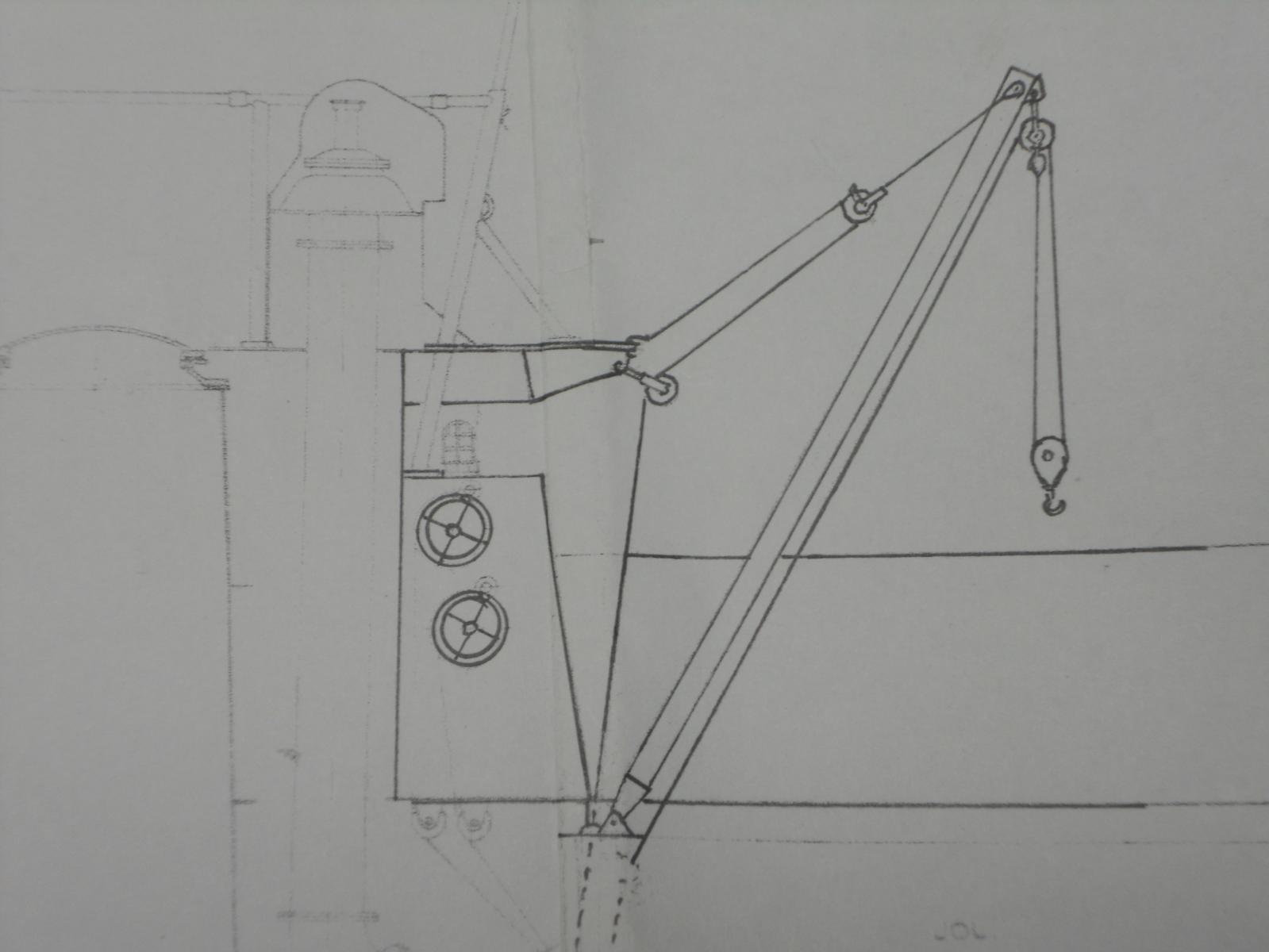
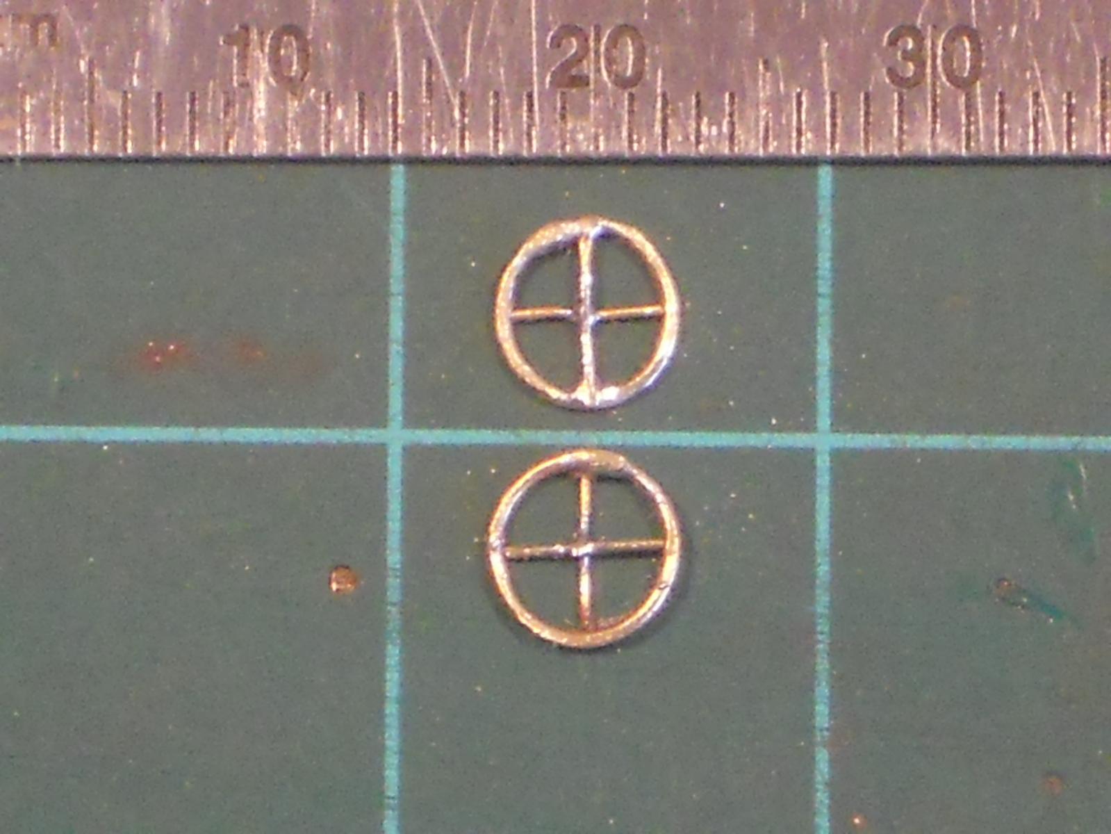
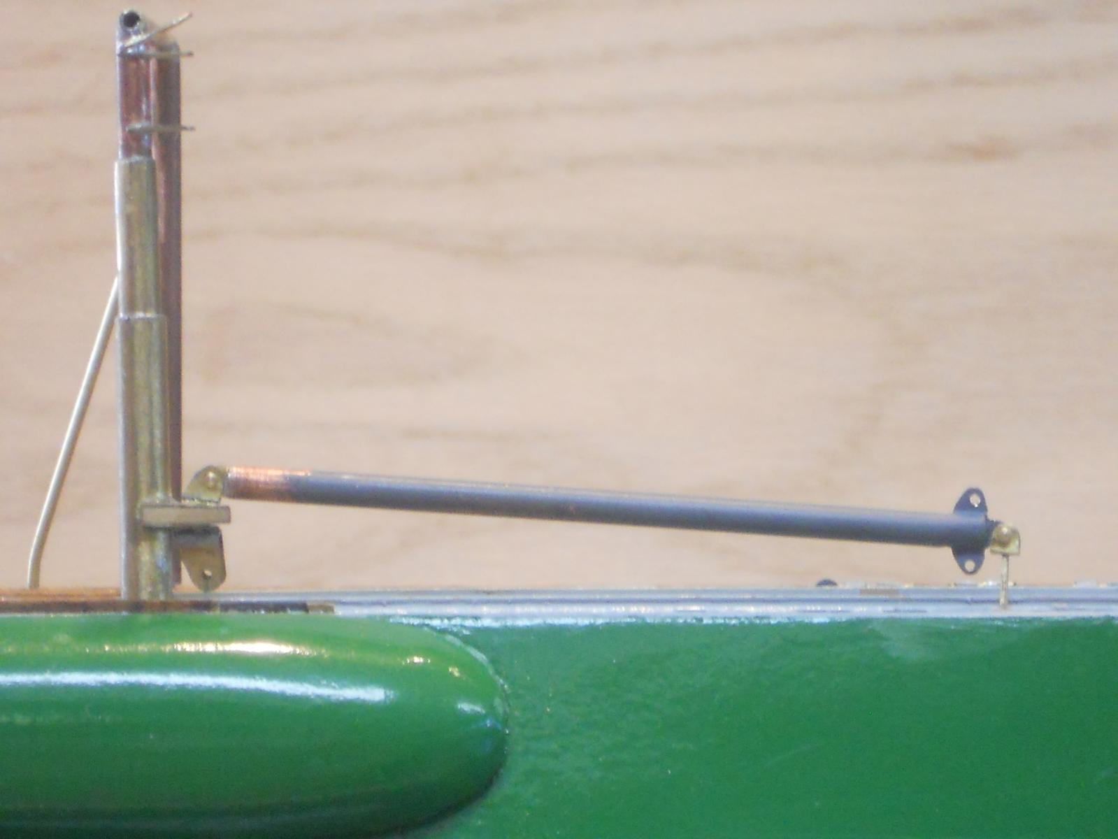
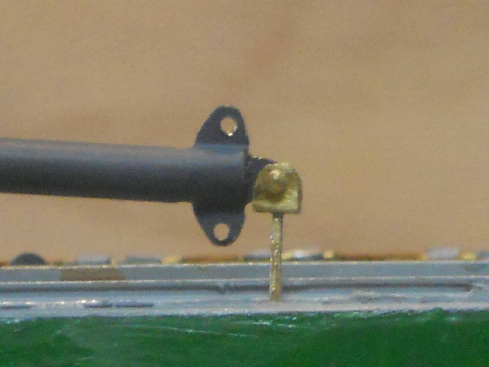
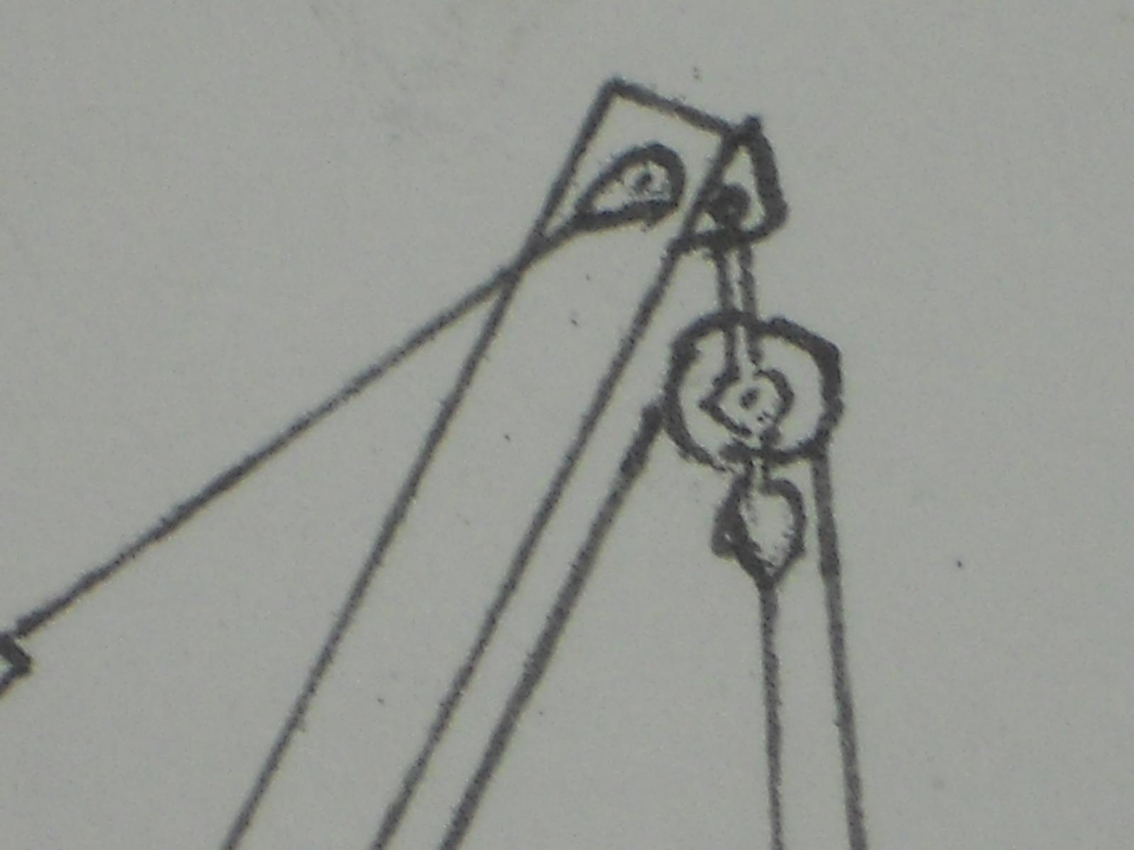
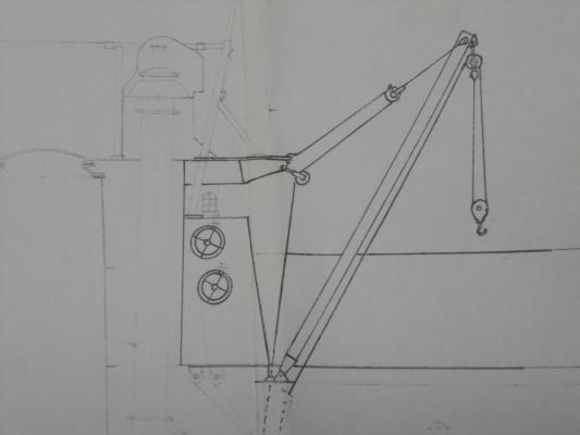
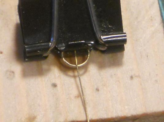
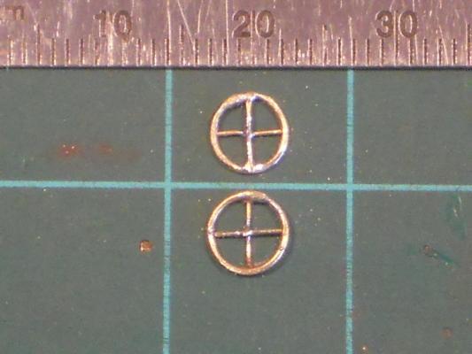
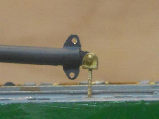
 My thanks to all who came to visit and liked my posts. Today was another doctor visit day and with doctor "Bendover" the proctologist. I'm kidding of course, his name is not Bendover but Ritter. We had good news and just keep on trucking This afternoon I made the dingy tackle handwheels that'll be cemented to the port aft side of the conning tower where the engine exhaust pipe comes up for snorkeling. I have a photo of the location but the exposure is such that the black painted handwheels do not show. But I do have a copy of a drawing so yuns get the idea where they are located on the boat. It was a little tricky soldering 0.1 mm brass wire to the 0.8 mm brass rod that I made into a ring of 5.5 mm OD. But with enough small heat sinks it worked okay. I also sprayed primer on the gantries and some of the attaching hardware. The rest of the hardware like the pulley brackets and so will wait till tomorrow after I mow the lawn. Well, that's it for now, pics below. This photo was taken at the commissioning of the O19 where I was present at the ripe old age of 4. You can't see the handwheels because they blend in with the black paint but they are located under the light fixture cutout. The drawing below will show it better. This drawing shows clearly where these handwheels are located and you can even see how the cables run. This show how I secured the 0.1 mm brass wire to the 0.8 mm brass ring. This steel office clamp also served as a heat-sink. To solder the cross spoke I used a second clamp, it was kinda getting crowded and had to crank the heat up on the soldering iron. This shows the completed handwheels. Don't forget that this is extreme magnification and shows all the little scratches and solder I was not able to clean away. This shows the torpedo loading boom secured to it's securing fixture that'll be cemented to the deck. It's now also painted as we speak. This is an extreme close-up of the boom secured to the deck fixture. Cheers,
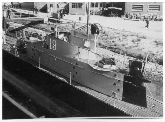

-
Hello everyone and thank all yuns who visited and left a like, much appreciated !!! Today I tried to finish both gantries. In reviewing the photos in my archive I discovered that I put the diagonal braces on the wrong post Soooooh - - - I desoldered them, filled the holes with solder and filed them smooth. Then I proceeded to drill the diagonal holes in the thinner / opposite posts and soldered the braces in and smoothed the solder out with small files. After they are painted nobody will ever know I had to make another set of the boom / pulley swivels and the ratcheting "come-along" for the aft side too. That ratcheting device gave me more of a problem then the first one. I screwed up one but the second try worked out okay. More metal scrap I also made the boom stowing brackets that'll be cemented to the deck. Another tedious part but they look rather nice. Sorry no pictures yet, forgot Well, that's about it for all the parts and pieces for the torpedo loading gantries and the dingy loading boom. Oh yeah, I started to to make the two tackle handwheels for the dingy boom tackles. These will just be dummies (like me) and cemented to the aft side of the con. Then that aft end of the con can be painted black. So, we are now ready for the pulleys, that'll be a fun project. Cheers,
-
I'll add my kudos as well Remco. It certainly looks very dark and I can see a few treenails too. Very nice looking wale. Cheers,
-
Hey Popeye, that deck looks incredible! If ever I attempt to do my Revel Thermopile I'll try to do the same, if I can remember Cheers,
- 165 replies
-
- 1
-
-
- united states
- revell
- (and 1 more)
-
Hello Ian, good to see you back in my shipyard, it's always a pleasure to see friends pop in. Thank you for your compliments and I'm glad you enjoy my explanations of the how and why's. Yes, the more I get involved with this build I also begin to understand my father's boat better. Cheers,
-
Hello John, very nice work - - - love those can't frames! Cheers,
-
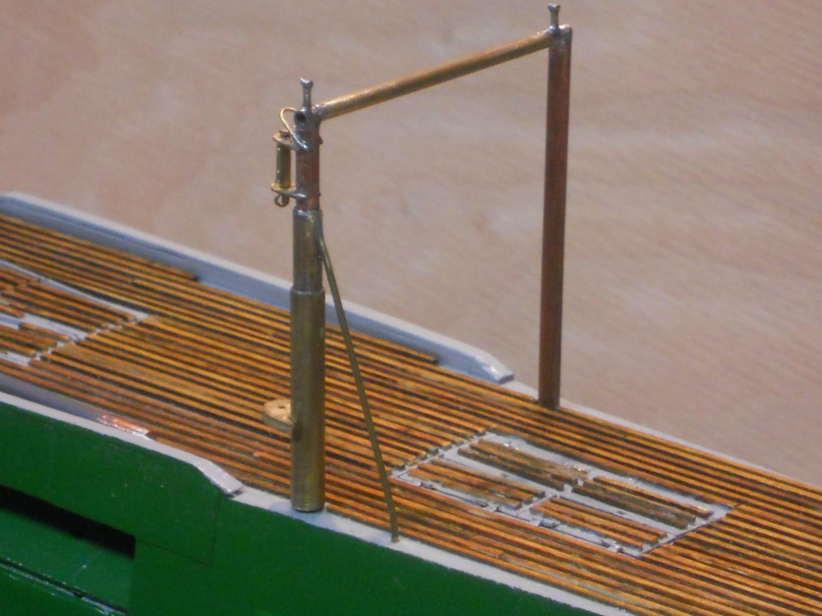
I thought to spend some time today doing some less tedious work and do some prep work for the antennas. Well, like all plans of mice and men this turned out to be even more tedious then the thimbles. I had to put two stand-offs on top of the forward gantry for the antenna support cables. I made these from small pieces of 1 mm brass tubing with a 1.2 mm long piece of 1 mm tubing on top, to cap it off so that I can run a brass support cable through them. First I took a length of 0.2 brass wire and stretched it to stiffen it by clamping one end in my bench vise and clamping the other end in a pair of vicegrips, then slowly pulled. Okay, that was easy. Next I cut 18 pieces of 1 mm brass tubing of 1 mm in length to simulate the cable tensioners. The actual antenna wire will be laced to this cable. Antenna wire by itself is not strong enough in that length without it being supported. These tensioners are a spring loaded device allowing the cable to contract and expand with temperature changes. I put them in a pill box for safe keeping. I drilled two 1 mm holes in the top bar of the gantry right above the upright posts and soldered the 5 mm long pieces of 1 mm tubes into them. Great so far. Now came the task in soldering the 1.2 mm pieces on top of these. First I filed a grove onto them lengthwise and tinned them, then took these small pieces between tweezers and held them on top and placed the soldering iron on top to let them solder together. After a few tries with cranking the temp up they finally held and I could clean the excess of with a fine file. Next i had to make a diagonal brace to help support the gantry vertical post on the boom side. This diagonal I made from 1 mm brass tubing. I drilled a 1 mm diagonal hole ⅔ up the gantry post and soldered a pre-measured piece of the 1 mm tubing into it and bend the bottom end to fit into a 1 mm hole in the deck. I cannot yet cement the forward gentry into the deck because i still need to make the boom swivel attach bracket with the pulley bracket and fasten to their support shoe. This and the ratcheting "come-along" has also to be made yet for the forward gantry. All the pulley sheaves can be made later and installed so that I can clean, prime and paint both gantries as soon as all the parts and pieces are made, hopefully in the next few days. Tomorrow is spend with doctor visits, so not much time for boat building. Nothing serious with these visits I only took one picture of the forward gantry to show the results of todays work or at least part of the work I did. No sense in showing all the minute pieces of tubing for the tensioners and the antenna support cable. That'll come when the antennas go up, pretty much at the final end of the build otherwise they'll just be in the way. This then is the forward gantry with the two antenna support cable attachment posts. As you can see the tops are the 1.2 mm pieces of 1 mm brass tubing. I'll thread the support cable through them with the simulated tensioners in front and to the aft end of them. They will consist of three of the small pieces of tubing for each. A dab of solder or 5 minute epoxy will secure them in place. The aft end of the support cable is fastened to the antenna bridge over the cockpit also with the tensioners. The actual antenna wire will be laced to this support cable and then led down to the radio room via a pipe on the starboard side of the cockpit. I also still need to make the DF antenna, that'll be fastened to the forward end of the cockpit shroud. Hmmm, so much to do yet. Cheers,

-
Batavia by *Hans* - FINISHED
Piet replied to *Hans*'s topic in - Build logs for subjects built 1501 - 1750
Hello Hans, beautiful carving my friend, your wife must be very pleased with the likeness Ref to previous post, yes, my Mulo experience ended in 1950. Reason for the stressful times were associated with politics and the general "we don't care" attitudes by the powers that be. A long story but this is not the place to get into. Cheers, -
Hello Nenad, she's looking really great, nice job!! Cheers,
-
Thank you all for visiting and your kind remarks - - - and all the likes, much appreciated!!!! @ Mark: Thank you for that great compliment It's been a challenge but very enjoyable and rewarding. @ Pat: Thank you too for your kind words. Actually I did set up an assembly line for the rest of the thimbles. I had to make 8 of these buggers with four of them narrow at the large end. Hmmm, a dozen eh? That's a tall order my friend, when do you need them - yesterday? - - - sorry, too late @ John: Nice to see you again and thanks for your compliment. @ Row: Thank you as well my friend. No, these parts are not for show but they actually work. They are sturdy enough to handle quite a (scale) load, and then some. The torpedoes and the mines will be made from wood, thus they don't weigh much and are perhaps even too light to make the "cables" taught enough to haul them up without jumping out of the pulley sheaf groove. @ Popeye: Thank you my friend, and yes, I can't wait to start making the pulley sheaves so I can actually assemble everything and doing a test run. Well, today I completed all eight thimbles needed for the front and back. I also managed to complete the aft gantry. All parts are now ready for primer and paint. I may take a run to the local sporting goods store and see what kind of line I purchase that'll look like steel wire rope in my scale. Cheers,
-
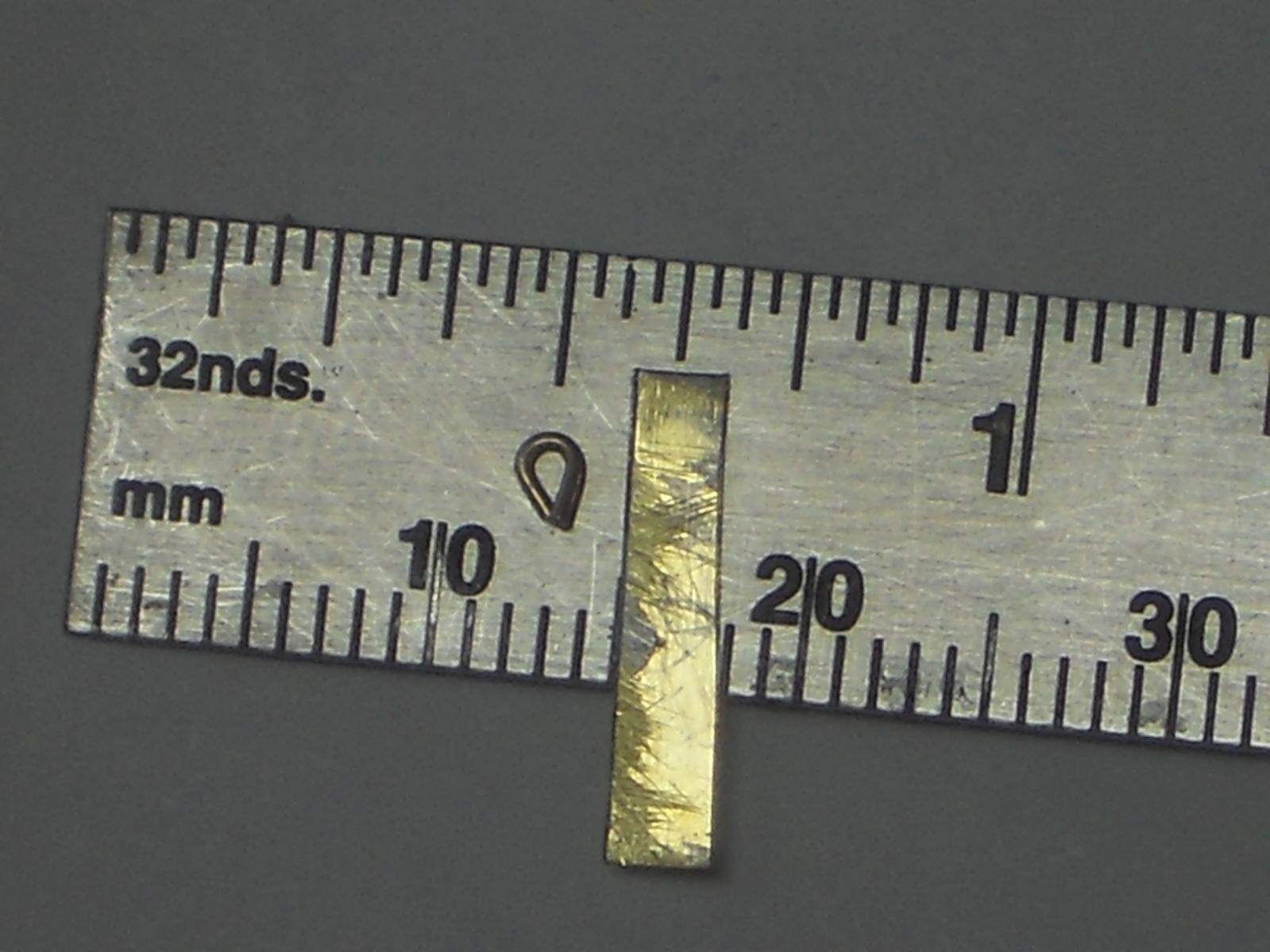
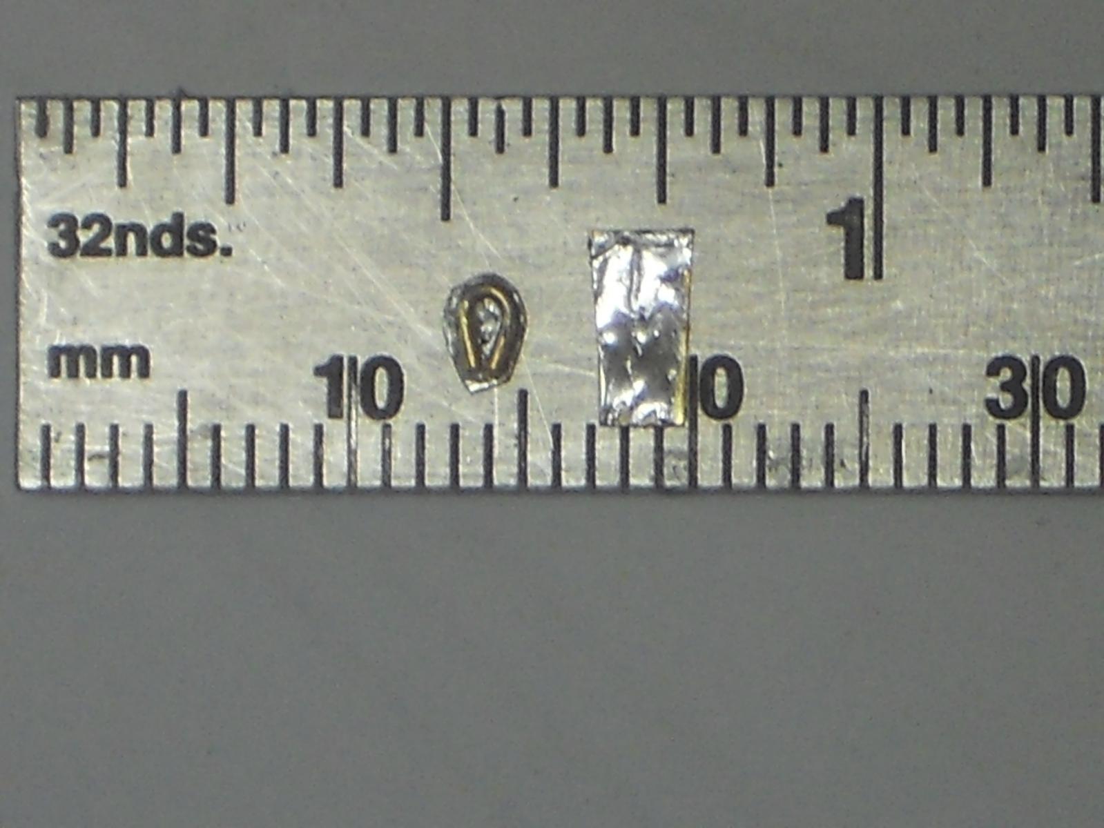
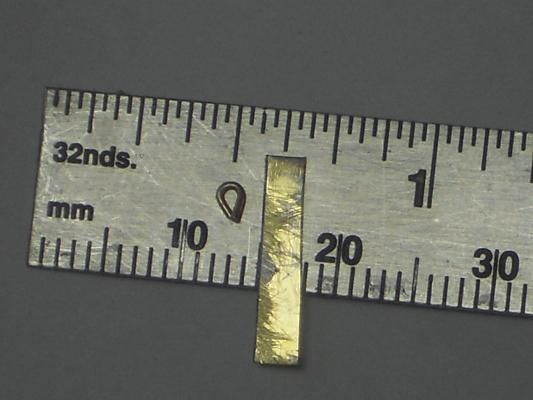
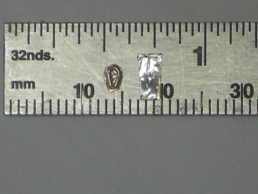
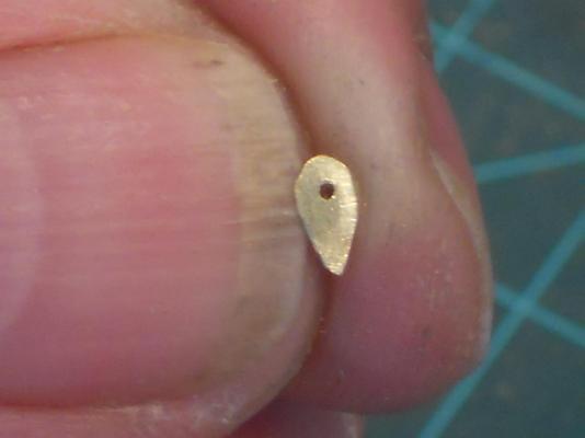
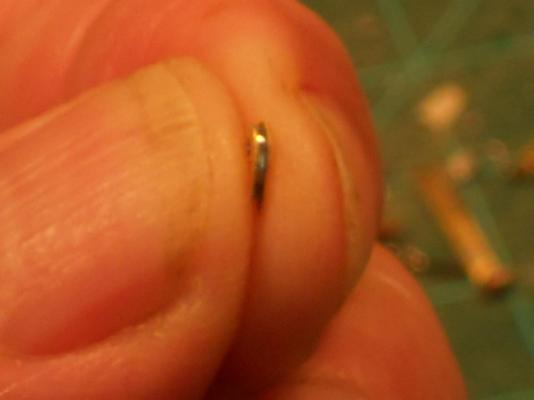
Thanks to everyone who came and visited my shipyard and your likes, much appreciated!! @ Ian: Thank you Ian for visiting. Yes indeed, the fingers do a splendid job but, as you said, they are also closer to the tools like files and drill bits. But so far I have been lucky with just a few minor scrapes and punctures. Today I finished up on all the pulley brackets needed for both the front and aft torpedo loading gantries and the dingy loading boom. Soooooh - - - I really needed to do something about those pesky thimbles. I wrecked my poor brain on that for several days in how in the world I could make thimbles close enough to scale. So, as I was mowing the front yard I thought about it and hit on a possible solution. It was one of those "ah yes, of course with a slap to the forehead" moments After lunch I went back into the hot garage and started on the prototype for a thimble. I took a 0.5 mm brass rod and bend it into a thimble shape as small as I could possible make it. I figured that if I sandwich it between two 0.1 mm brass shim pieces and file then to be a little larger then the bend piece rod I would have a workable thimble. After about one hour I had the prototype done and found it to be quite workable. I even wrapped a 0.021 inch rigging cord to it. This'll need some practice or go for a smaller diameter cable. I may have to visit a sporting goods store for fishing line as John Texnn5 suggested. Now that I had the process pretty well in hand I made the second one, which turned out really good and is just slight larger then scale but once on the boat it'll not be too noticeable, I hope This one took "only" 45 minutes. Then I made a second one and that one came out slightly smaller yet, so I know that I can make them close to scale. The problem comes in with the center hole for the attaching pin. This is the limiting factor in size and I must be satisfied with it. Okay, here are a few pics showing me efforts with the thimbles. This shows the parts for the thimble. A smal pice of 0.5 mm brass rod bend into a thimble shape and a piece of tinned 0.1 mm brass shim. I put them on my ruler to show the size. This shows the second step in the process. I first soldered the rod part to the tinned brass shim, then shaped that to a little larger then the rod piece. Next I drilled the hole in the center of the bend rod for the attaching pin. The next step is shaping the brass shim to slightly larger then the rod and removing some of the excess solder. Then I soldered the second piece of brass shim to the rod piece and final shaping the whole assembly. There is really no way to hold that in a pair of pliers so I first cut away most of the excess with a pair of scissors and then filing. Yes, my poor left index finger took the brunt again with the file I now reverse drilled the hole in the second shim piece and started to dress everything with a fine file. This shows the completed prototype and as mentioned above, the seizing of the cable needs work. I'll have to make a jig to hold this thing so the cable doesn't come off and unravel on me. This is a face side of the first production thimble, and this is the side view of the first production thimble. Cheers,
-
Hoi Remco and Mark, yupper, I'm having a ball - - - does it show ??? I also like a challenge (at times ) and these tiny things are surely taxing my abilities. When it comes out okay you should hear the whooping and hollering in the shipyard and give myself a high five. You think I can now graduate to miniature ships in bottles and lamps?? That project is still pending but first I have finish this sub though. Thank you both for your compliments, I really appreciate it.
-
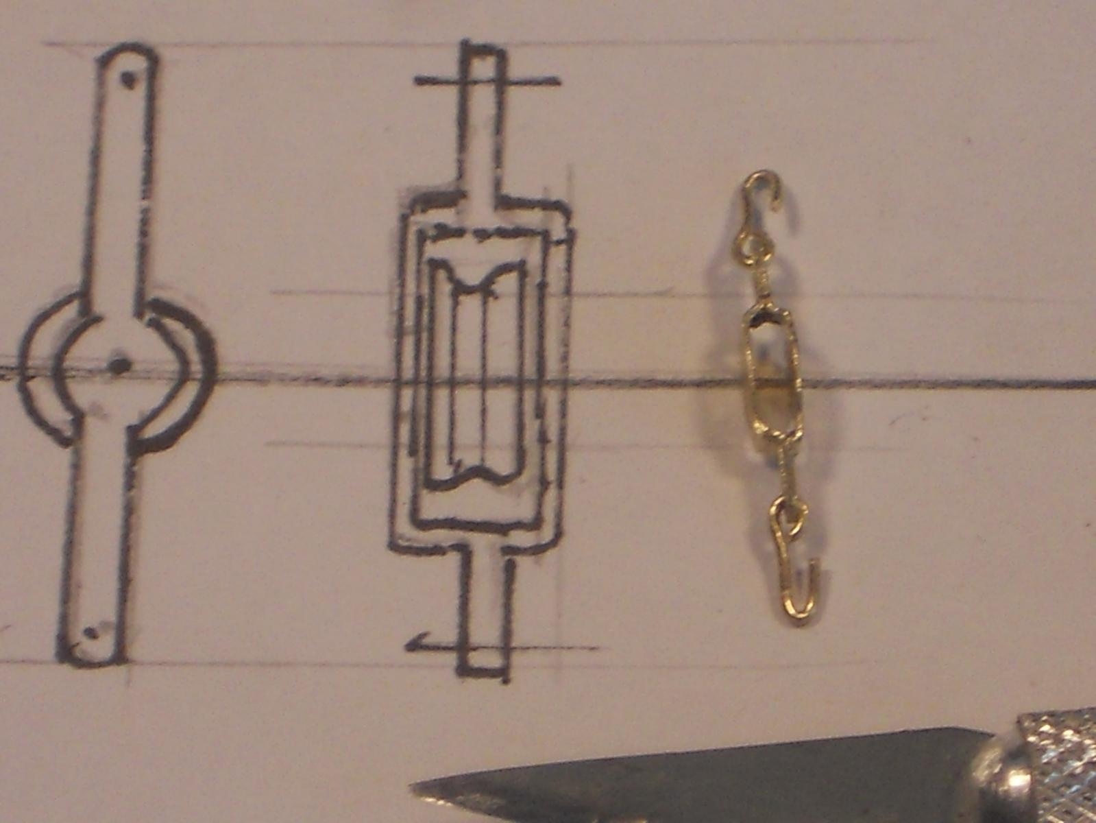
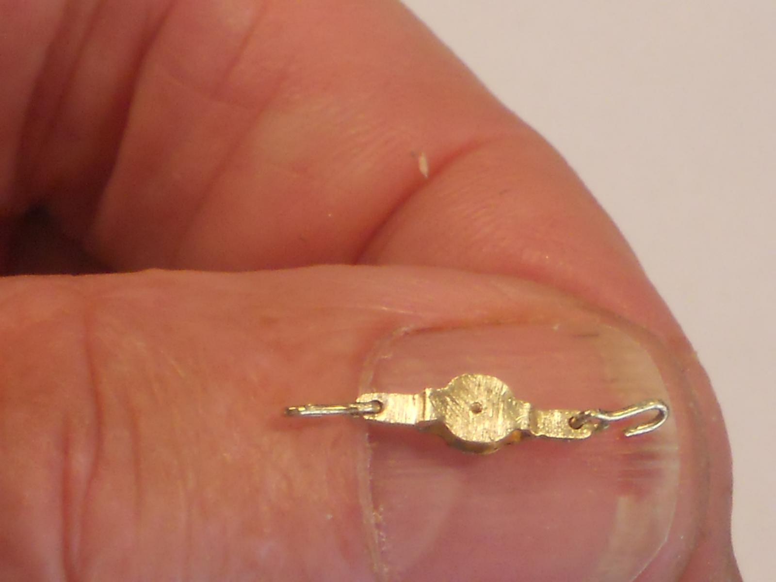
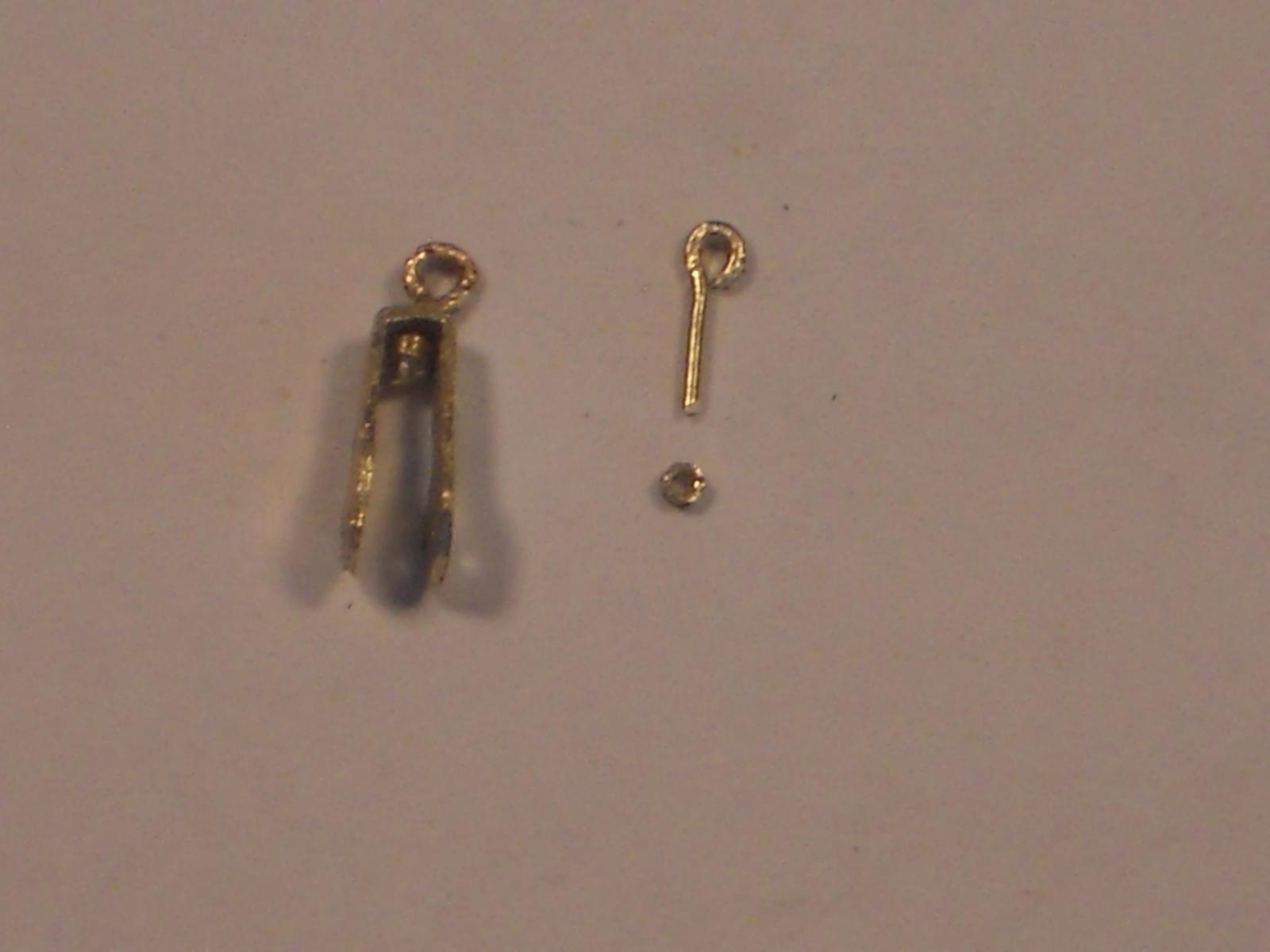
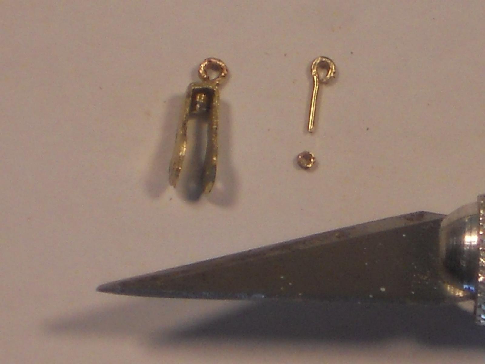
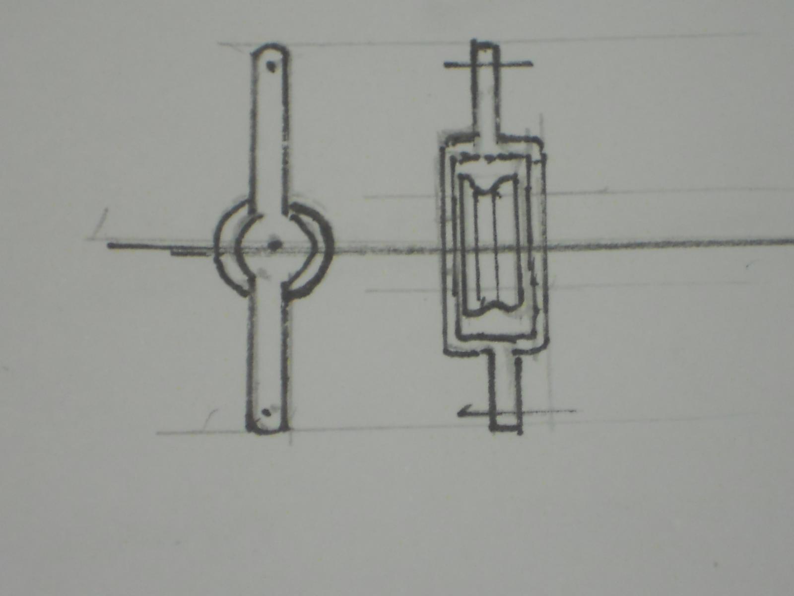
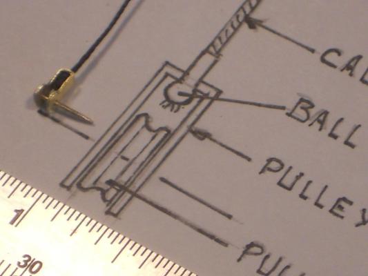
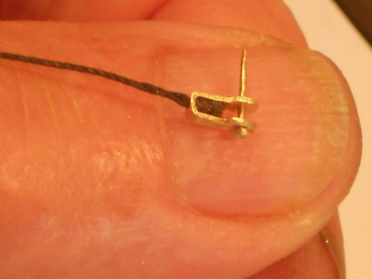
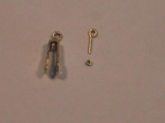
After some garden work I ventured back into the garage a k a shipyard, and tried to finish the dingy boom pulley brackets. Got all but one done. The raw parts were already made last Friday so I could dig right in. I started with the top of the boom "loading" bracket. That one seemed to be the most troublesome because of its shape and not much to hold onto. I shaped a small piece of wood to fit inside the pulley location and now I could hold it with a small pair of pliers and my left hand fingers. This worked just fine and I managed not to ruin it. After this was done I made two hooks to attach into the holes at each end. Holes are #77 drill bit for all. Next came the idler pulley with that funky ball end to the cable that attaches this pulley to the top of the boom. That worked out okay as well, so far no goof-ups I used a piece of 0.021 inch rigging cord as cable, poked it through a small hole -#77 drill - and tied a knot in it on the inside of the bracket to simulate the ball end. The other end will have to go over a simulated thimble. Okay, so far so good, knock on wood The last one I could manage to do today was the pulley bracket that hooks to the top of the AA gun deck. For that one I thought to put a swivel-able eye in the end where I can attach a hook into. This may be to large of an assembly and will most likely make another one that can be pinned directly to the "steel" part of the AA gun deck per the drawing. I started with the final pulley bracket that hooks onto the dingy or whatever other light loads we may have. It can even assist with loading the torpedoes. Here are a few pics for yuns to view and critique. This shows the "load"pulley bracket that'll hook to the top of the dingy loading boom. The next pic shows the side view. This is the side view of the load pulley bracket and yes, all of the brackets still need some final trimming with a small file or sandpaper on a stick. Yep, that's blood under my nail, poked it with a brass rod trying to pick it up. Mutter, mutter, domkop. This show the next pulley bracket I have dubbed idler pulley 1. You may be able to see the knot inside the bracket. This is another view of idler pulley 1. it's 0.15 mm thick. The bleeding in my thumb stopped and I cleaned it with some water and ordered all the germs to stay away, or else This bracket I dubbed pulley bracket 2. The way I made that swivel-eye is to first make an eye rod from 0.5 mm brass and a small piece of 1 mm OD brass rube. The thickness of that piece of tubing is about 0.2 mm. I first drilled a hole through the end with a #77 drill bit, then inserted the eye rod and held it with a small wooden clothe pin. Holding it straight up I then clamped the clothe pin in my mini vice and then soldered the tubing piece to the pin. I lucked out that I didn't solder everything solid, it swivels !!!! Yeah, it's getting pretty long this way and then with a hook yet. This is a close-up of all the parts. And yes, it still needs some cleaning up with fine sandpaper and then we can prime and paint everything. Cheers,


-
Thanks to all for hitting the like button, it's really appreciated. @ Al: Thank you again for visiting my build and appreciating my work. @ Row: Thank you for the compliments, I'm blushing Well, you'd better believe me about the size of my hands, they are really rather small with long, thin fingers. That trait runs in the van Warmerdam family, many artists. Cheers,
-
Hi Popeye, Never heard of lacquer bursting into flames as you described, that's news to me. When we were painting aircraft as part of our business we elected not to use lacquer anymore, too labor intensive and too problematic. Acrylic enamel, urethanes and epoxy paints. After the EPA rules on stripping we gave that up and just did sand a paint. I'll stick with urethane anytime or enamel. Keep up the good work, and have a fire extinguisher handy Cheers,
-
Hello Al, Just got caught up with your build, fantastic work! Here I am a certified machinist but your equipment might as well be from another planet to me My training dates from 1952! Never earned a living as machinist though, just used all my training in my business repairing aircraft. And thanks for visiting my father's submarine build, appreciate you stopping by and liking my work on her. I'll be visiting your shipyard more often, that new fangled stuff is intriguing to me. Like to see the continuation of your build. Cheers,
-
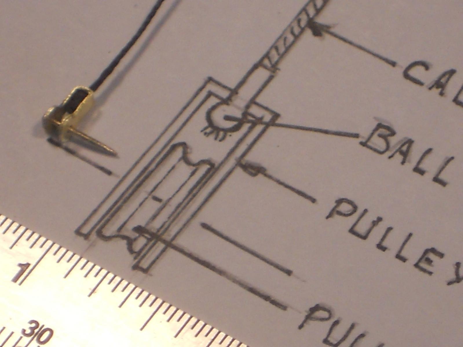
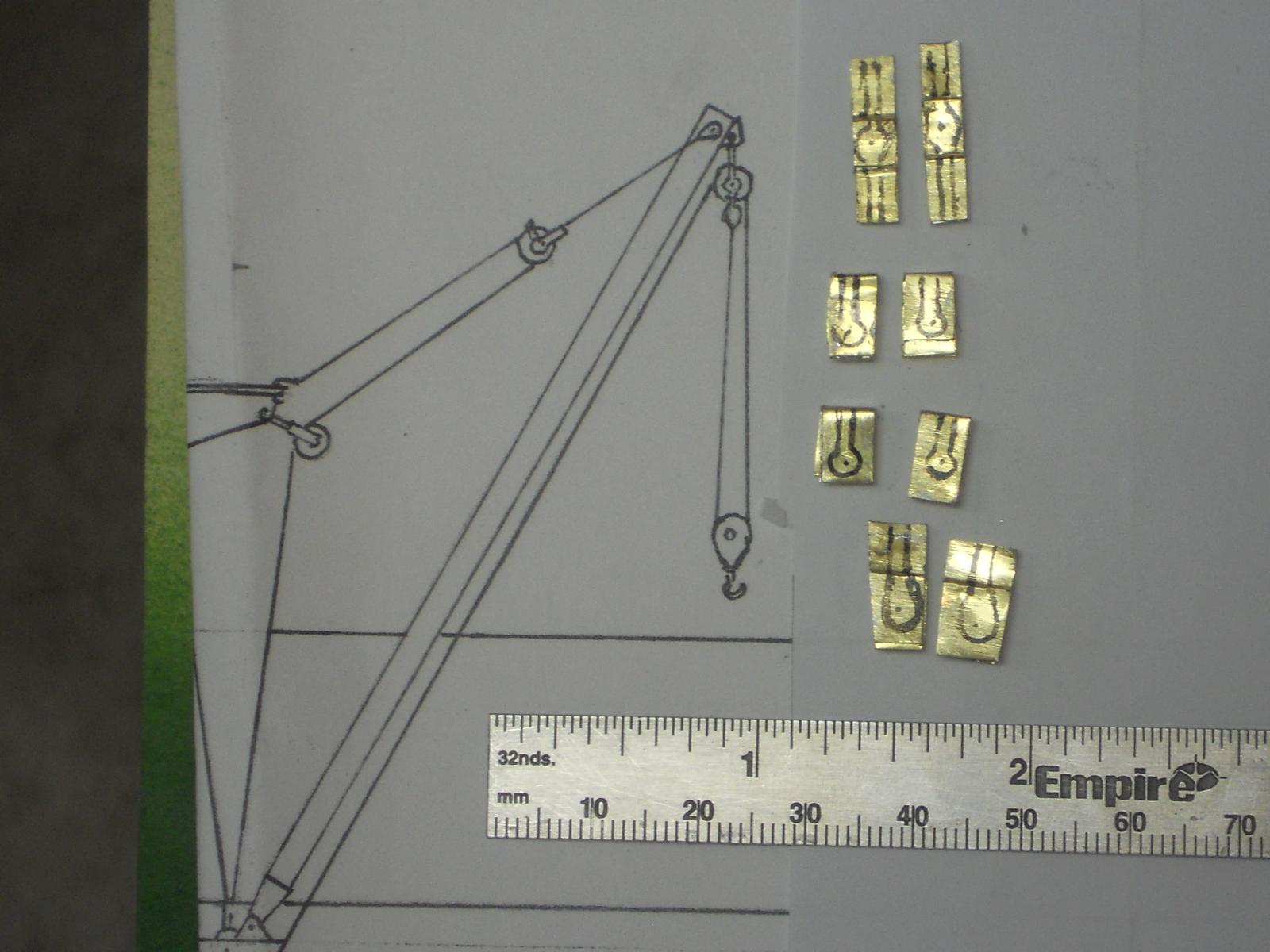
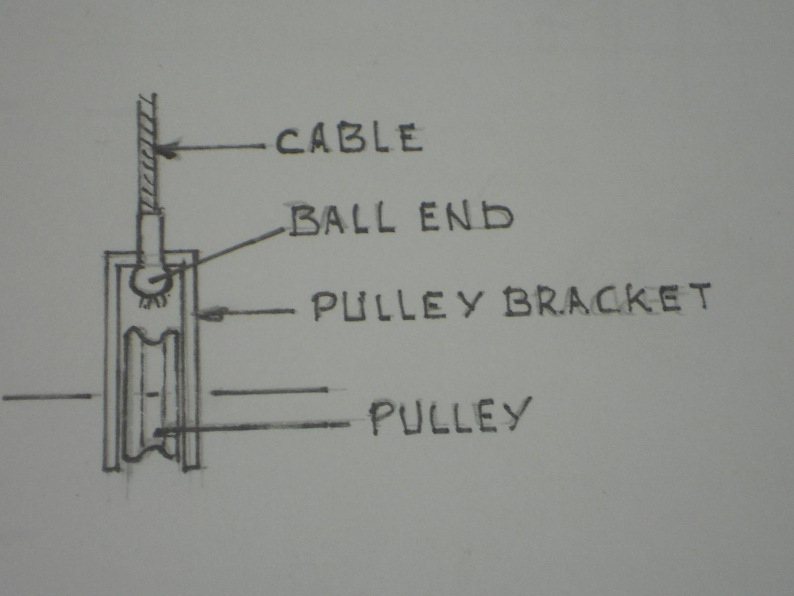
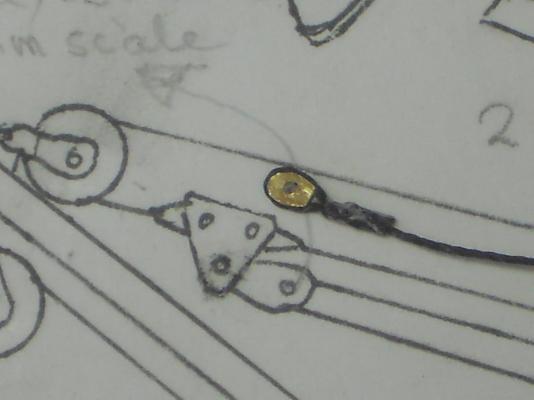
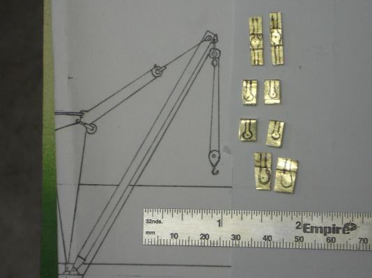
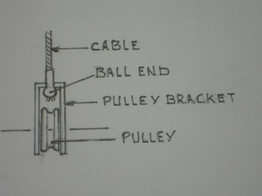
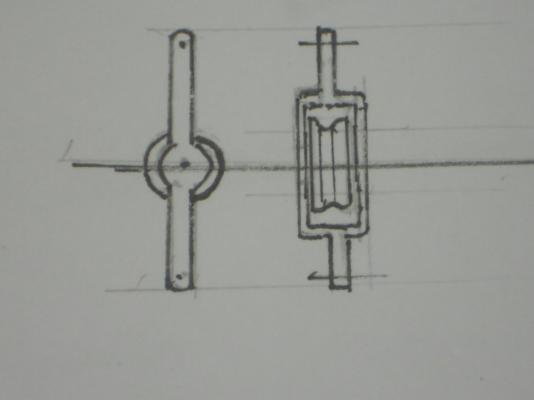
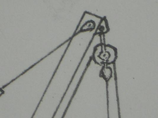
Hello everybody and my sincerest thanks for all who visited and clicked like. So today I had to remake a few of the 3 mm pulley brackets for the dingy loading boom. They are all still in the rough state and require a LOT of filing to produce the final product. I'm afraid that I have to leave them a little larger then scale otherwise they cannot be handled. We are definitely not going to do 0.1 0r 0.005 millimeters Even so, I'll try to make them as small as possible so that I can still drill the holes for the hooks and the pulley sheaf pins. This'll be a try as I go project, that's why the extra brackets - - - yeah, my mammy didn't raise a dummy Here are a few pics of today's status. Here I have laid-out all the pulley brackets in the same order as the dingy boom arrangement shows. The 2 top ones are for te load pulleys. I made a spare for each one just in case I screw up. The middle four are for the idler pulleys and the bottom one is for the hook that holds the dingy or whatever is needed to be hoisted. This shows how I intend to hook-up the top idler pulley. This particular method is employed in aircraft control cabling. The "ball end" is crimped to the cable with a special tool. They may not have had this system before WW II and could have used a brass soldering system with regular steel cables. The other end of the cable is attached to a thimble that's bolted to the boom. I'll try come up with simulated thimble and a hook. I like the idea of having everything in a quick disconnect method. This shows the bracket that's hooked to the top or end of the boom. When you look at the sketch on the top picture the ends above and below the pulley will be the most trying parts to model. I just need to have enough material for a hole to attach a hook to the top end and a "ball end" on the lower part. This is shows the top end of the boom with the load pulley. I'll use a hook to attach it to the boom and a bal-end on the bottom instead of a thimble. Cheers,
-
Hello Nenad, good to see you again in my shipyard, you are always welcome - - and I love your humor! Hmmmmm, eyes on E-Bay eh? That would have been cheaper then having had a double cataract operation done. Well, actually that didn't cost me a penny, insurance paid it Right eye is 20 / 20 and left eye is now 25 / 20, not too bad. I also use a 3 X magnifier like reading glasses. Works great for me with good lighting. Your CS is coming along real great my friend, I love the looks of her !! Cheers,
-
Batavia by *Hans* - FINISHED
Piet replied to *Hans*'s topic in - Build logs for subjects built 1501 - 1750
Hoi Hans, Yup, and Mulo too! I like to forget those years, real stressful for me. Cheers, -
Can't tell the difference from here Remco Looks real to me ! Cheers,
-
Hi again Sherry, n i i i i i i i i i i ce !!! Cheers,
-
Hey Popeye, nice piece of work on the planking !!! Bravo. Yes, lacquer doesn't like humdedity. When I was painting airplanes in New Jersey I had to use a retarder when spray painting, which is not really that good for the durability of the paint but one has to do what one has to do. Other then that, I do like the end result with lacquer though, 16 coats hand rubbed !!! Although it's now superseded by much better paints. You gonna buy some more of that lovely lumber? It really makes the model outstanding. Cheers,
- 165 replies
-
- 3
-
-
- united states
- revell
- (and 1 more)
-
Hoi Remco, AWESOME ! ! ! Tool and die maker now too? This is so much better then "store bought" stuff, don't you think? The satisfaction of having made such a first class tool is well worth it. Just like with me, with all those compliments, just watch them shoes though that you don't trip over them