Piet
-
Posts
3,568 -
Joined
-
Last visited
Content Type
Profiles
Forums
Gallery
Events
Everything posted by Piet
-
 Hello Gary, Great to see another "iron" ship being build for a very worthwhile reason, to honor your dad. As my signature indicates I am presently building my father's submarine, also to honor him. When I started this build I struck out getting drawings or photos of the boat. Koninklijke Marine (Royal Navy, Netherlands) - zero. Navy Museum - zero. The Navy Archive was closed due to digitizing all microfilm but one of our friends here at MSW was able to sweet-talk them into letting him do the research and printing. Also very expensive, 10 Euro per print ! He and several others steered me to archives for photos, of which I have now quite a good collection. Not easy, being that I am working on a pre-WW II boat ! I'll be looking in at your build. Cheers,
 -
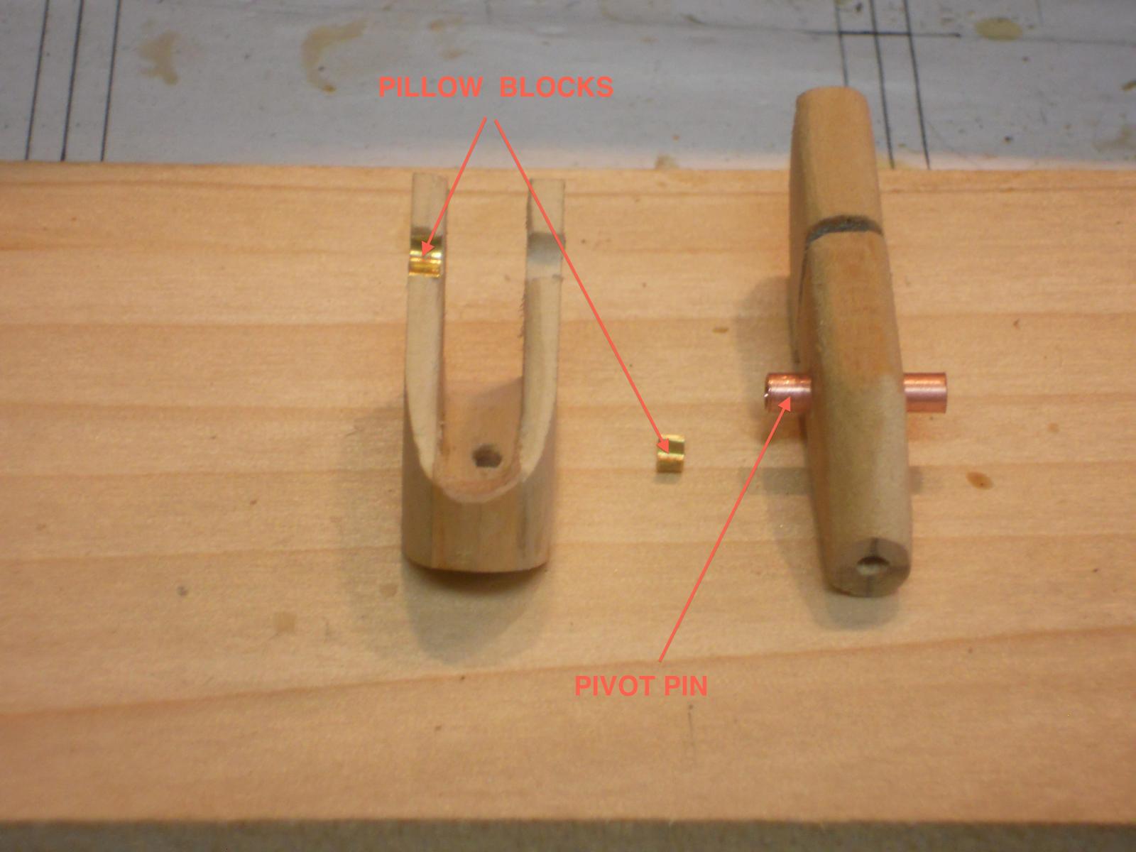
Thank you all for dropping in and your likes, it's much appreciated. Well, I had a change in plans. Instead of cementing the small pieces of tubes to the base unit and using a smaller diameter tube as pivot pin I decided to use pivot bearing pillow blocks instead, much like the real gun. I had to remove the already installed copper tube from the central barrel housing and replace it with a longer one that would now rest on the pivot pin bearing billow blacks. So far this worked quite well but now I had to make the closing saddles for the pivot pins and used a thicker brass sheet for that. I cut a few strips of 2 mm wide and shaped it around a steel pin of the same diameter as the pivot pins. This did pose a few problems and had to scrap two till I had what I wanted. I also glued the barrel to the center barrel housing using a 2.5 mm diameter wooden pin. I was quite happy that everything lined up nice and straight Then I started with the gun adjusting wheels and got as far as making the rims. The five spokes will be another story and need to make a jig for them. I also made the 90* drive unit for the gun rotation mechanism. This was all I could do today, not much progress because I had to do some necessary correspondence after lunch. Okay, here are a few pics. This picture shows the two baring pillow blocks for the barrel unit. I cheated by installing one piece of tubing through the barrel unit instead of "bolting" them individually to each side. Hmmmm, I may fake the attaching hardware with paper parts. There is not much space inside the base unit. These bearing saddles are from thin brass stock and epoxied in. Here we see the gun barrel glued to the center barrel housing. Both barrel pivot pin bearing saddles are now epoxied in. We also see the hole for the future rotation pin to the deck plate. The pin is made but I want to wait till most of the detail stuff is finished and installed to the gun. This is a shot looking at the business end of the gun. I put the barrel assembly temporarily to the base unit but had to keep it from tilling forward with a small pair of pliers. This shows the 90* drive for the gun rotation adjustment wheel. The rims are made and waiting the spokes and drive pins. Here you see one of the wheel rims temporarily placed on the drawing of the base unit to look for fit. Looks okay to me. This pic shows the barrel unit pivot pin locking saddles. Another view of these locking saddles Cheers,


-
Hello Peter, Very nicely done, a lovely little working boat. Congrats with your 25th wedding anniversary and many more. Cheers,
-
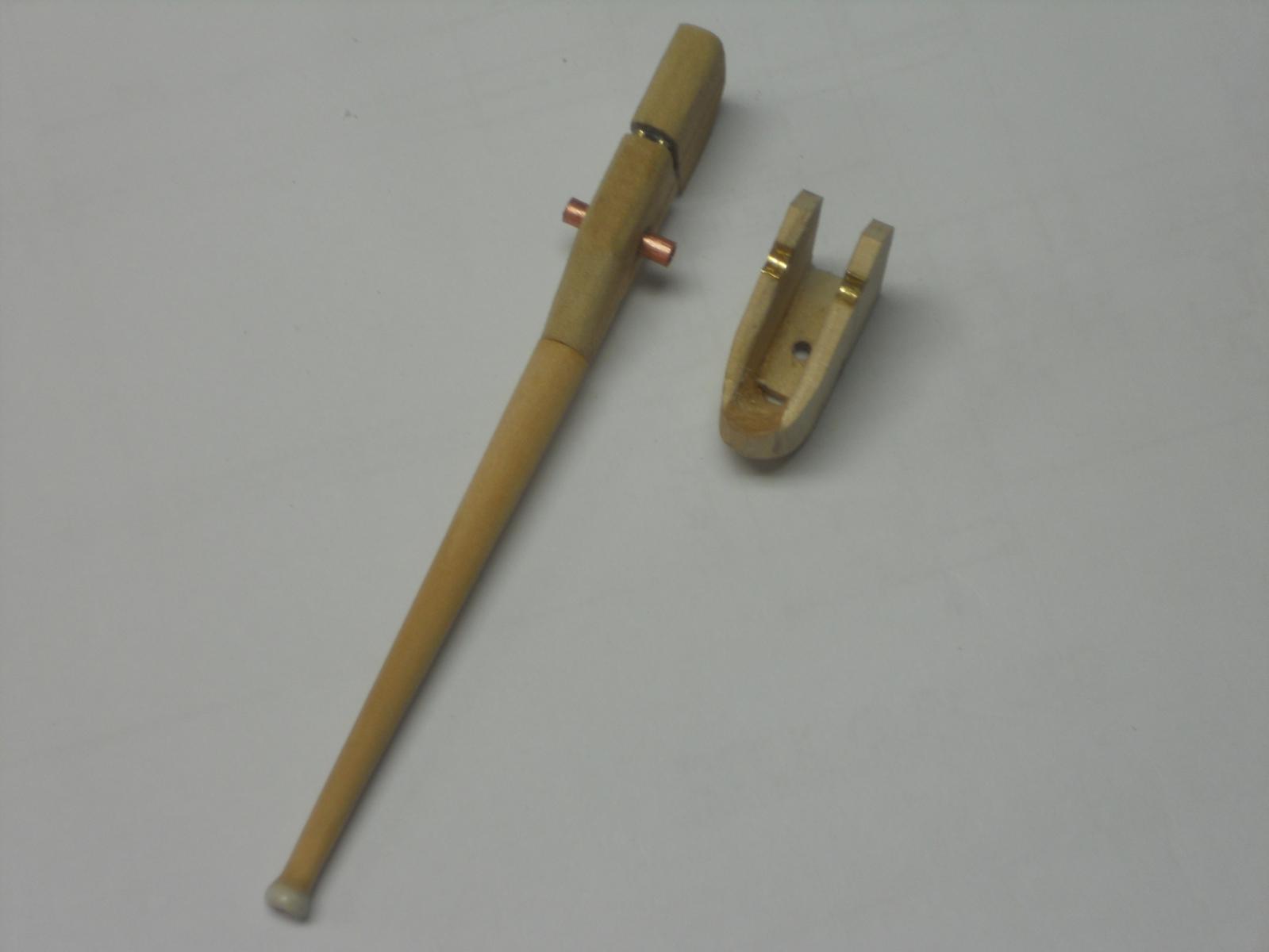
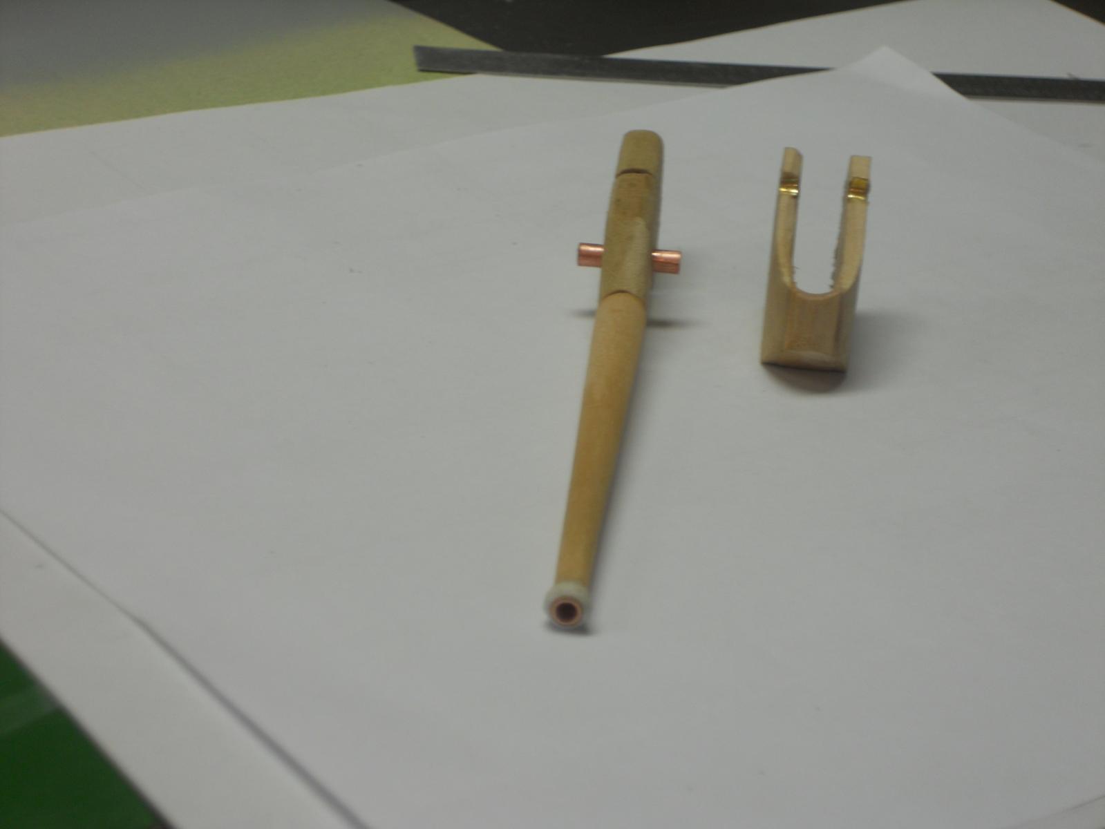
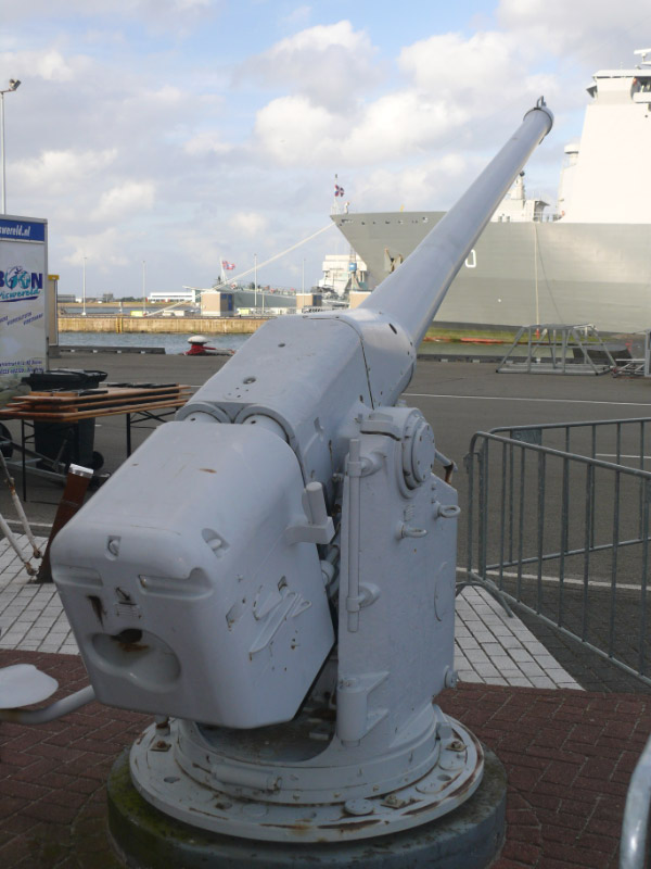
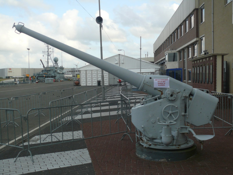
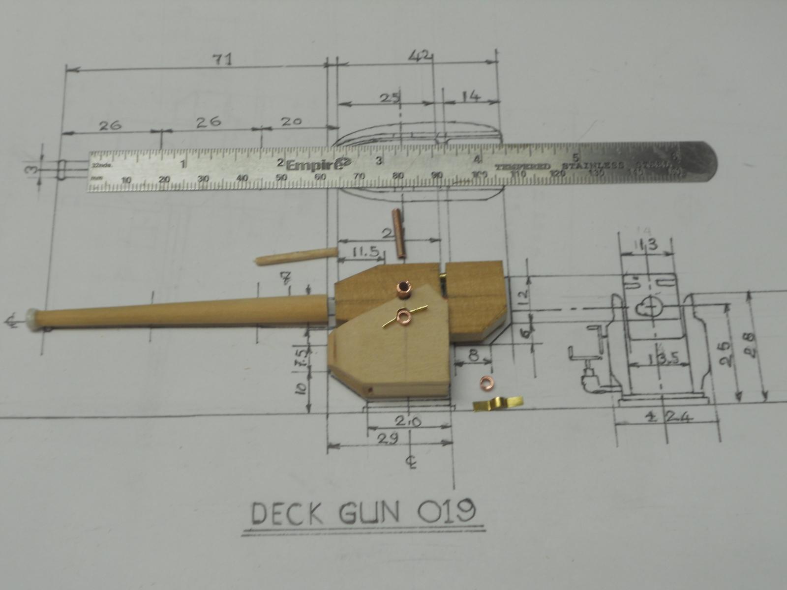
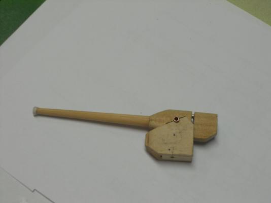
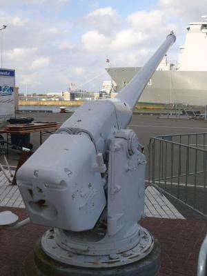
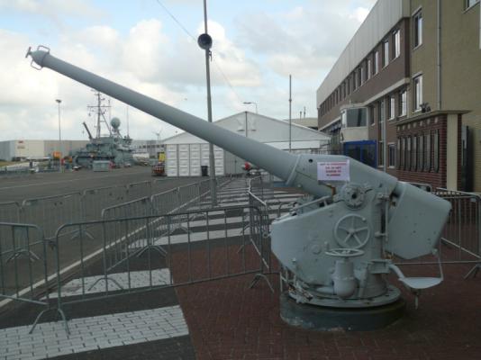
G'day to all and thank you very much for looking in and your likes, it's much appreciated. I continued with the deck gun in between some domestic chores. The main parts are made but need to be refined yet. Still a lot of work to be done with the small details. I'll post two pics of an actual deck gun that Freek send a few month ago for yuns to see what I'm trying to achieve. They disappeared from my build log and have not yet had the chance to put them back. BTW, quite a few pics have disappeared, arch The actual deck gun on display at the Navy Museum in den Helder, the Netherlands. This shows all the major parts for the gun. I finished the barrel and inserted a 3.1 mm copper tube in the muzzle end. It will be attached to the center part with a wooden dowel, which is shown above left of the gun. The aft part is attached with 2 small 1.5 mm brass tubes and a 3.1 mm copper tube in the lower center as part of the barrel. The two small tubes are most likely for the shell casing discharge gas to the breech assembly. I am inserting a 3.1 mm copper tube through the center part for the hinge. The hinge pivot pin is a 1.5 mm copper tube. I cut two 2.5 mm long 3.1 mm copper tubes to be cemented to the base as hinge bearings, I put them on the base unit just below for yuns to see and where they are supposed to go. Hinge bearing retainer straps are from 0.2 mm brass shim stock that'll be cemented to the base kinda modeling it after the real gun. I hope to be able to also use very fine sewing pins as the attaching bolts. As you can see there is still a lot of work yet to be dome but so far I'm pretty happy with it. Cheers,
-
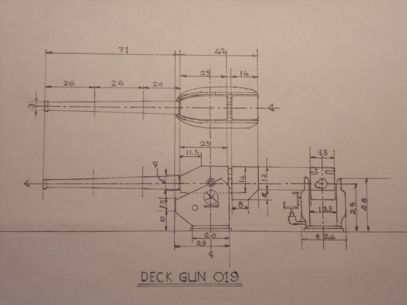
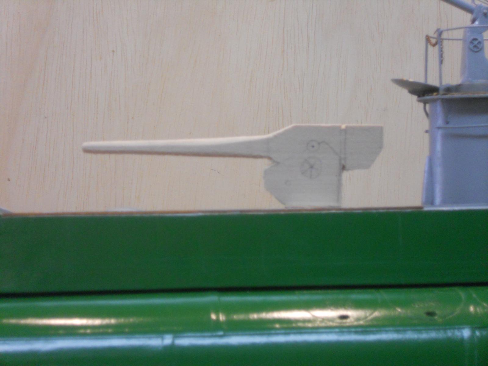
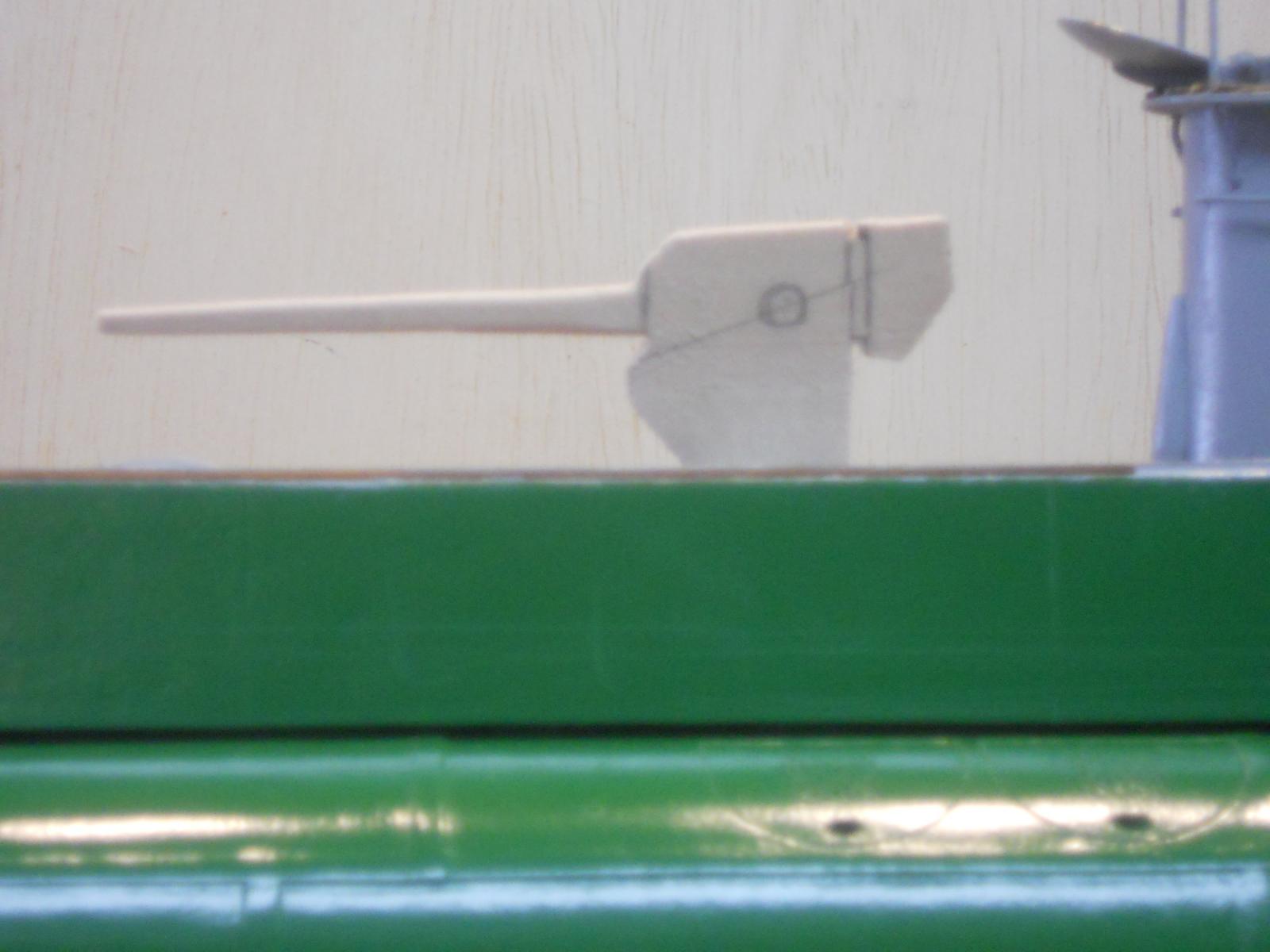
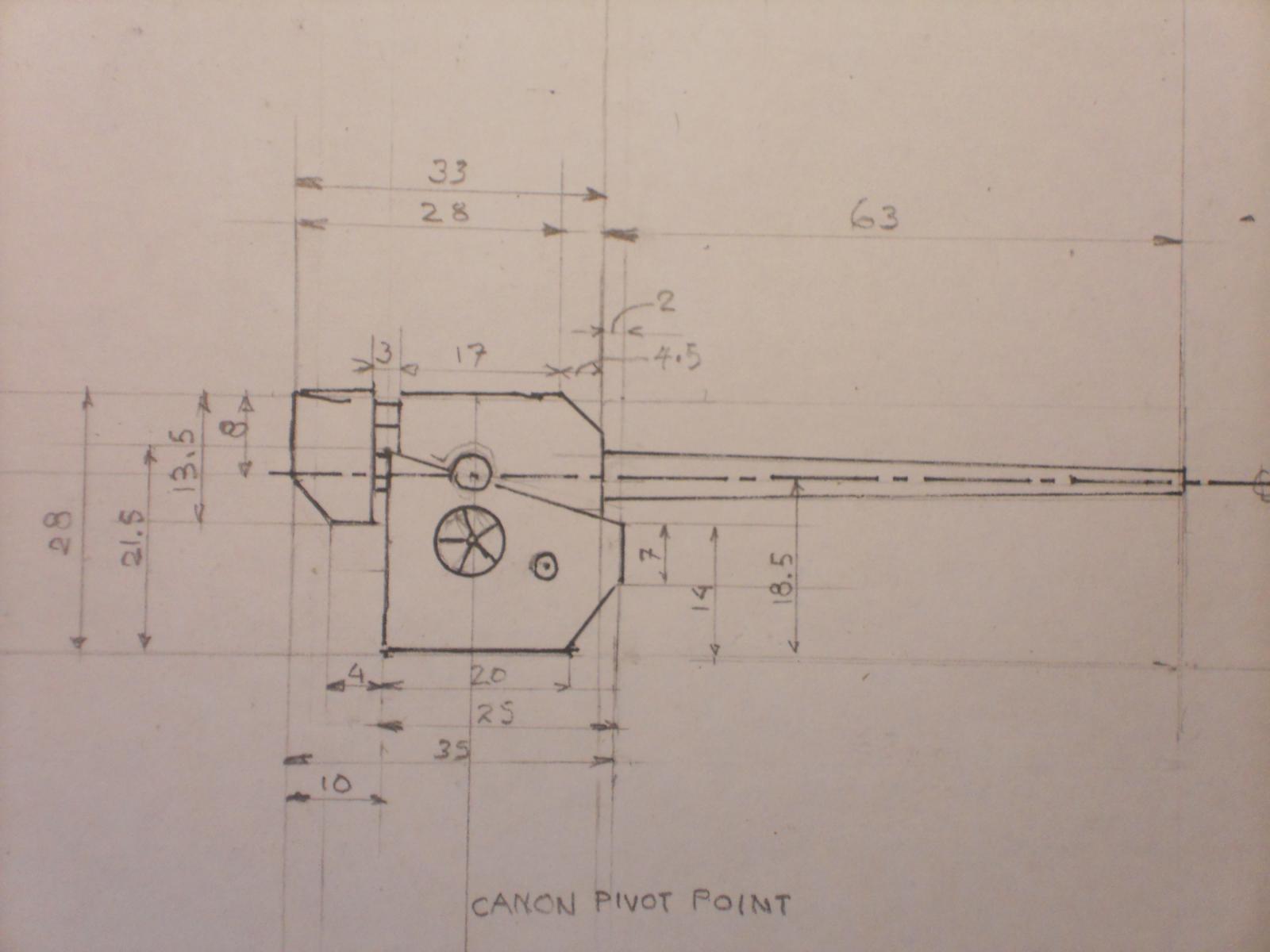
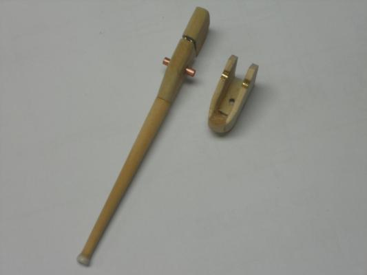
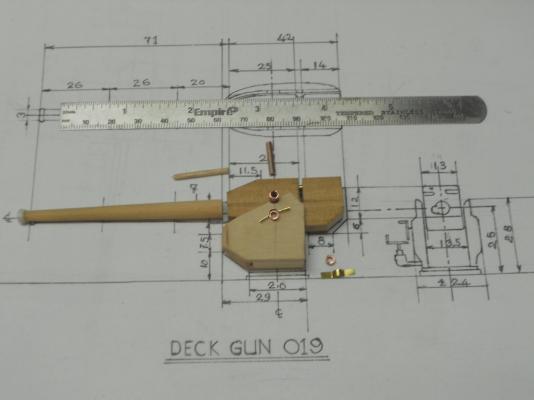
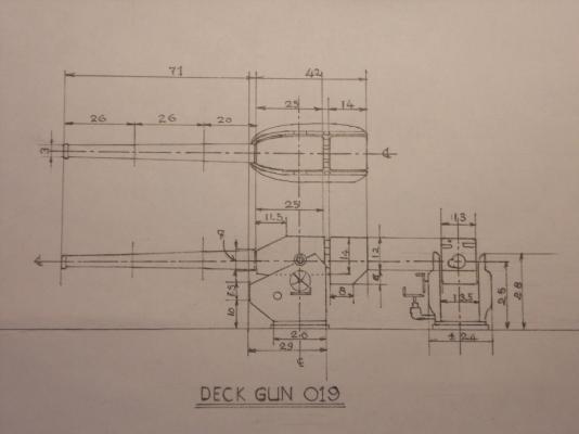
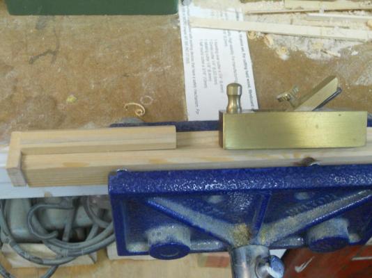
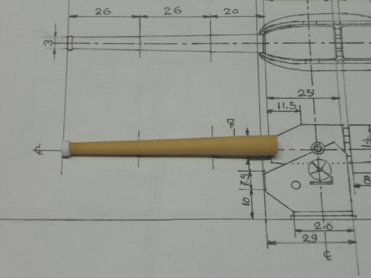
Hello fellow ship builders. I have been taking it a little slow, trying to give my poor back a chance to "un-strain" itself Weeding in Florida seems like a full time job, everything grows like the dickens. In any case, that gave me some time to redraw the working drawing for the deck gun. I made another sample gun from the new drawing and I'm much happier with that one. So I started making the gun I made the base from two peaces of 2 mm boxwood with a 14 mm block in front that'll be shaved nicely rounded as the original shows on the photos I received from Freek. I made the barrel also from boxwood. I had a piece left over from the VOC ship masts. Most of it was shaved off on my mast making fixture and the final rounding and tapering was done on my Unimat DB 200. Hopefully I can finish the gun sometime this week and then proceed with the torpedo loading gantries, for and aft. That'll be a can of worms due to the small size of the tackles. Everything will be made from brass. Okay, enough of the jabbering and time to add a few pics. This is the redrawn working sketch for the deck canon. Some of the measurements will most likely change a little as I proceed. Here is the mock-up according to the second drawing. I like the size much better, it's just about the right height. Like I mentioned above, the actual canon may have to be adjusted here and there but overall it'll work out okay. This block of boxwood was build up from three pieced and glued together to prevent warping. It was fortunately long enough for the barrel. First I used a small plane to reduce the size and make it round enough to clamp it in my lathe. Sorry, no pic of the lathe work but the taper was done using two hands and finalizing with a file and sand paper. The bulbous barrel end still needs to be finished and then finish boring the barrel and put the rifle grooves in it - - - NOT Here is the almost finished barrel. I did a Doris on the barrel end, I glued a strip of paper on the barrel end and will shape that nice an round, hopefully. Cheers,

-
Thanks Michael for dropping in and your compliment. After I was discharged from the Royal Airforce as an aircraft mechanic I wanted to go back to school and complete my studies for flight engineer with KLM. Something happened and couldn't go so I solicited for a job as draftsman with a engineering firm in the Hague. I also had an application in with KLM as mechanic and when they called to come to work for them I accepted and went to Amsterdam to work for KLM. Never got to actually earn a living as draftsman but, as you said, the training is invaluable. Well, actually when i was director of QC and Engineering for an airline near Philadelphia I designed a cargo interior for a few of their aircraft. I'd love to learn CAD but at this stage in my life the time to learn it is not worth my while. Too busy with modeling and my art. I'm painting and drawing freehand between model building Cheers,
-
Ah yes I remember the flying SF ! Hmmmm - - - she needs a set of wings then Cheers,
-
Wow, thanks to the many who clicked on the like button, that's really encouraging. Ahoi Mark, thanks for dropping in, it's always a pleasure "seeing" you here and your kind words. Yeah, after seeing the mock-up on the boat I decided to make it just a tad larger. In between some rest periods I started to redraw the gun and used the prints from the manufacturer as a guide. I think it'll look a lot better. I have thrown my back out weeding the front lawn last Tuesday and need to give that old poor back a little rest. Yeah, I could make a few rounds that size on my DB-200 and make some black powder, then get some cotton balls from Sjors and bingo we can bango Hey Daniel, good to "see" you again too. Hope all's well in your neck of the woods. Thanks for your compliments. Some time ago I did contemplate of buying drawing software but it would have taken me at least 6 months to basically understand it and how to use it. Computers and me don't mix very well So, I decided to just do it the way I was taught, T square, triangles and etc. Thanks to a very understanding trade school director I obtained certificates in 13 trades that included technical drawing and illustrative drawing. In my many moves I lost my drafting machine. It was big and cumbersome so I'm back to T square and triangles. I get a real kick out of doing this and used the same method when designing my VOC ship "Surabaya." Cheers to all,
-
That's outrageously gorgeous Sherry. That blue reminds me of flying at flite level 30 !! Cheers,
-
Hello Popeye, one word - - - NICE !!!! Cheers,
-
They look terrific Peter, congrats Waiting actiously for the final rigging. Cheers,
-
Well, instead of making a cardboard model of the deck canon I made one from that pesky balsa wood. When I placed it on it's base and looked at it with my eyes at deck level I think that it is a tad too small. Reason being that according to a few photos I have with crew members, it shows that the barrel pivot point is at waist level or top of the side railing and the top of the gun to just below the shoulder. Naturally I used by body to measure and I realize now that I am rather small thus the discrepancy. As mentioned above, it's a rather small gun but a little larger then I am showing here (see pic below) Soooohh, I'll add about one or two mm to the overall height and one mm to the aft side. The reason for this is that turning axle below and in line of the barrel pivot point I need some more material at the backside. I'll redraw the gun and at the same time I can now also draw the front, rear and top views as a guide to make de canon. The barrel is another issue. It'll be made from a brass or copper tube, encased in either skulpy or wood. The canon base and top will be from wood with perhaps the base covered with brash shim. Just thinking out loud, I'll see what develops. I'm not going overboard with this thing [pun intended], as long as it looks like the canon on the actual boat. Perhaps you may think that I'm being anal about a few mm but this is such an easy thing to do right. When we consider that the AA gun deck is at eye level then the top of the gun should be at the con handhold. There is also a base platform to consider that'll raise the gun by 1 mm, so I'll really have to watch my next measurements. But I think that you all agree it's a little too small, wether it's 1 or 2 mm. Cheers,

-
Thanks to all for your like votes, it's much appreciated. Remco and Jan, you guys have more confidence and faith in my abilities then I deserve. The desire is there but it's practically impossible. I couldn't even buy the tiny gears to make the barrel movement or the gun mount movement. Did yuns see the measurements? Oh I know yuns are just mess'n with me - - - but I love it. Hmmmmm Jan, life ammo - - - well, perhaps if we put a few 22 caliber rounds in some Preparation H and shrink them - - - but even then they'll still be too large According to the spec sheet the deck gun was an 8.8 cm (3.5 inch) rifled barrel, and fired shells, much like a high powered assault rifle. That works out to a bore of about 1.76 mm for the model. Now we all know that the German 88's were a fearsome gun and very effective but still no match for the 6 inch guns on the US subs like the USS Cod I visited last year in Cleveland. Compared to them these were just pea shooters. The shells were stored below and brought up via a "dumbwaiter," or lift as Dutch and our English cousins would call them. At least the US subs didn't have an elevator, chock one up for Dutch ingenuity Cheers to all,
-
YES !!! That looks really good Nenad, just like a picture frame. i wouldn't fret too much about the colors, you'll figure it out oaky after some more light sanding and match it with the deck or leave some contrast - - perhaps? Isn't scratch building fun? And talking to yourself too? I do that all the time and even scolding myself when I have made a mistake Cheers,
- 4,152 replies
-
- 2
-

-
- cutty sark
- tehnodidakta
- (and 1 more)
-
Hello Dan, those iron straps do look like hot hammered iron, hammered to the required thickness by an experienced iron worker. i.e. they look authentic !! That was not an uncommon practice in those days, many other parts were made from wrought iron. One of my trade certificates is smithing and iron work. Cheers,
-
WOW !!!! Sjors, that planking and filler job is just exquisite !!! And BIG - - - now if you build a second one then you can strap them to your feet and with a paddle you can walk on water You have water in Holland?? Okay, okay, sorry for the sick jokes, she's really looking great and so is Anja's Halve Maan, unless she treated it with preparation H Please say hi to Anja from this crazy flying Dutchman Cheers,
- 1,616 replies
-
- 2
-
-
- caldercraft
- agamemnon
- (and 1 more)
-
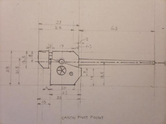
Hello all, Well, my wife's sister and husband departed last Monday to go home to the Netherlands. I may now have a little more time to devote on the O19 model between some needed domestic chores. Yesterday I spend most the time in the front yard though, weeding and mowing the grass. In doing so I must have strained my back and it hurts like the dickens, so I took it a easy today. I calculated the measurements for the deck gun and made a rough profile sketch to see how it would look on the boat. I'll make a cardboard cut-out first, if that looks good then I'll either finalize or redraw it. I'll also make sketches of the rear and front before cutting wood and / or metal. This thing turns out to be smaller then I figured and may have to forego the rack and pinion gearing inside the gun mount. The barrel assembly will rotate though as well as the entire gun. Here is a copy of my sketch. Cheers,
-
Now that looks super good Nenad, great fix! Love that half round moulding. Cheers,
- 4,152 replies
-
- 1
-
-
- cutty sark
- tehnodidakta
- (and 1 more)
-
Thank you all for your very kind support in your comments and "like" votes, it's not just for me but I see it as including my father who, I'm sure, salutes all of you. Mark, Sjors and all, I may seem to include my father a lot in my posts but y'all understand that he is the reason for this build and thus - - - - - For many this is just history and interesting but If I can make this history come alive and make you all a part of it because one of you on this forum is a living link to that history - - - that'll make me extremely happy. Yeah Shors, the O19 was indeed build close to where you live but we also lived nearby in Vlaardingen. But that was way before you were a gleam in your father's eyes Well, on to the next model, the deck gun, which has several parts or models, as Remco so aptly states !! Cheers,
-
Hello Michael and thanks for dropping in. When we arrived back in Holland after the war from the Dutch East Indies in 1947, I received three or four glossy black and white photos of the O19 when she was launched and one when she was commissioned with two pics of my father. My uncle, who was my father's best friend gave them to me, that was all I had to remember my father by. It was not till I started this build that I began accumulating a massive amount of photos through the help of Remco, Gino and Amateur Jan. I am glad all who visit enjoy the pics and related history, It's obviously very close to my heart. Cheers,
-
WOW Remco, very nicely done, congrats with that excellent bit of mortising. And you'll solve that door problem too, I'm sure. Hmmmm, 4.5 years into it and still have do how many more volumes???? Well, at least that'll give me the incentive and a very good reason to avoid that famous bucket - - - so i'll not kick it Cheers,
- 1,215 replies
-
- 1
-
-
- sloop
- kingfisher
- (and 1 more)
-
Thanks everyone for visiting, for your most generous comments and your "like" votes. Still no time yet to spend in the dockyard, still involved with entertaining Gwen's sister and her husband. We went to St. Augustine yesterday to visit the alligator farm / zoo, most impressive. Traffic was horrific, too many people due to "spring break." There is a replica of some sort of 16th or 17th three mast ship tied up there but Gwen read a sign that said it's a restaurant. Guess we'll have to go for a look-see. We also visited the old Spanish fort and I took a few pics of the cast bronze canons. I really need to go out into the bay to take a few pics of the fort from the water side, there are a few paintings brewing in my mind of Spanish treasure ships tied to the docks in front of the fort. Well, at least this post has some nautical info I hope that next week I'll have more time to devote on my dad's O19. Cheers to all y'all,
-
Hello Sherry, I have been silently following your magnificent build but can't resist saying, some very nice carving !!! Cheers,
-
De Zeven Provinciën 1665 by Dražen - Scale 1:45
Piet replied to Drazen's topic in - Build logs for subjects built 1501 - 1750
Hello Dražen, that's magnificent decking !!! Cheers, -
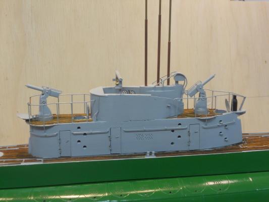
Well, it's been a few days since my last post and thank you all for your patience I have been busy entertaining Gwen's sister and her husband - - - soooooohhh - - - nut much work was done. But it's all been very nice and great for Gwen to be able to chat with her sister, getting updated on all that's been happening with the family back in Holland. However - - - - I have been able to sneak some time in between all this family stuff though First I redid the slats on the dingy hatch doors, starboard side, they are now looking straight. Next I completed both AA guns by adding some things to them and painting them. So in effect, the conning tower is completed except for the antenna wires, but those will be done as the final last things on the boat. Next month I'll start making the deck gun, I think. Here is the pick with the completed AA guns ready for action !! Forward and aft AA guns completed and placed in their buns, ready for action. They can be completely pushed down and the lid closed. They have hand wheels on the sides to swivel the guns up and down for tracking aircraft and shoot them sown. Cheers,