Piet
-
Posts
3,568 -
Joined
-
Last visited
Content Type
Profiles
Forums
Gallery
Events
Everything posted by Piet
-
 Fantastic and out of this world !!!! Awesome work. Cheers,
 -
That's beginning to look really great Nenad. I can't wait till the final deck is done, all scraped and smoothed out and weathered. But i have patience - - - a little Cheers,
- 4,152 replies
-
- 1
-

-
- cutty sark
- tehnodidakta
- (and 1 more)
-
Ahhhhhhh, some more eye candy to feast my eyes. Great stuff Remco, just magnificent. And a scylpy mattress, not so good for the back though but it looks real, great job, very innovative. Cheers,
- 1,215 replies
-
- 1
-
-
- sloop
- kingfisher
- (and 1 more)
-
Hi Adriaan, looking fantastic from Florida But I know what you mean, paint and photographs do show everything that's not quite right. Keep plugging at it my friend till you are happy. Cheers,
-
Hi Boris, That model looks very familiar - - - that's got to be a Dutch submarine Wow, very impressive model my friend. I hope that you'll have many buyers for it. Cheers,
-
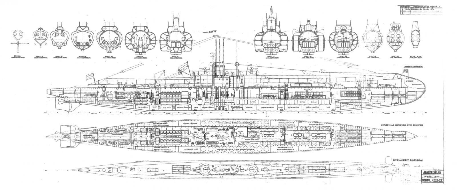
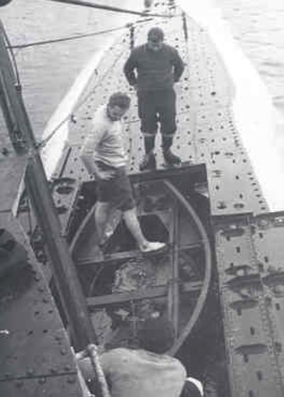
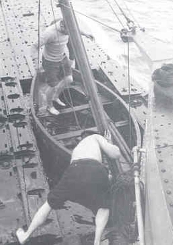
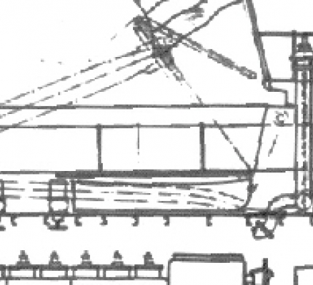
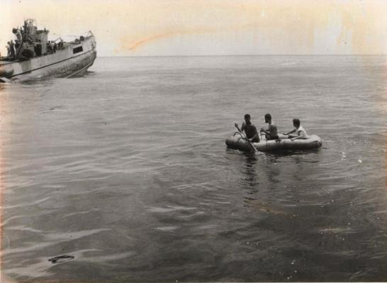
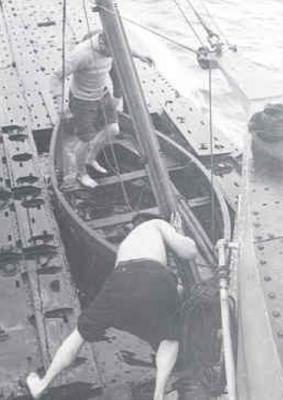
My thanks to the many who visited and clicked the "like" button", and you know who are are it's much appreciated. To Freek, Gino and Ian and others who may have silently questioned the same thing, thanks for your comments on the dingy or jol in Dutch. Lat year I guess, Gino and I had a private discussion about this little dingy or jol about the same issue. Was it stored upside down or right-side up. The question is of course either we have an air bubble trapped inside the little boat or it's always filled with water when right-side up. Either way, the solution would obviously be holes do let the air escape or to let the water drain out. This all sounds very logical and without having much or anything to go by it'll become a guessing game. Before I had concrete proof that I was fortunate to obtain in the meantime, I opted for storing the dingy inside side up with a few bung holes in the hull somewhere, but most likely the stern bulkhead. They could have used either rubber or wooden "bung hole" plugs to close the holes. I also thought about wear and tear on the holes, how would they hold up in use. Where would these alleged holes be, in the bottom hull planking? Would they be thick enough? Would there be some sort of reinforcing? However, when Remco send me a copy of the general layout of the O19 and a few other drawings from the Dutch Naval Archive, the dingy shows stored in the inside out position. See copy 1 below. I enlarged that particular section for y'all to see that it was placed in the inside out position with the bow forward. See copy 2 below. Right now I'm not going to argue with the drawings and accept them as fact. I also have a few pics of the O19 when on Ladd Reef where they were just extracting the dingy from it's little "house" and lowering it into the water. As y'uns can see the dingy is already in the inside out position hanging from the loading boom See pic 3. Ah, but we could say, well they could have turned it over before the pic was taken. Yes, they could have but is that what happened? Without anything to go by the best we can do is give it a "swag" and no one would be the wiser, at no fault of ourselves. I just was extremely fortunate to have received the needed info from my dear friends Remco, Gino, Boris and Fred Huijgen, not only about the dingy but other details as well. Lo and behold, I also received a few pics of the O21 where they were in the process of taking the dingy out of it's little hangar. See pics 4 and 5. Here we can see clearly that the dingy is in the inside out position on it's cradle. I trust that I have now satisfied the questions and opinions, and accept the shown facts that the dingy was indeed stored inside up. How the water drained out when surfacing I'm going to leave up to our imagination. At this scale it's not important but I do have my thoughts about that . Cheers,


-
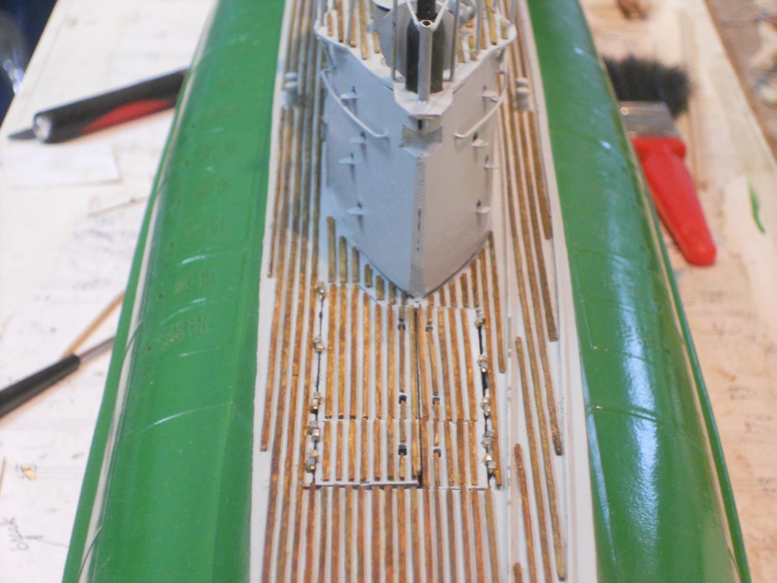
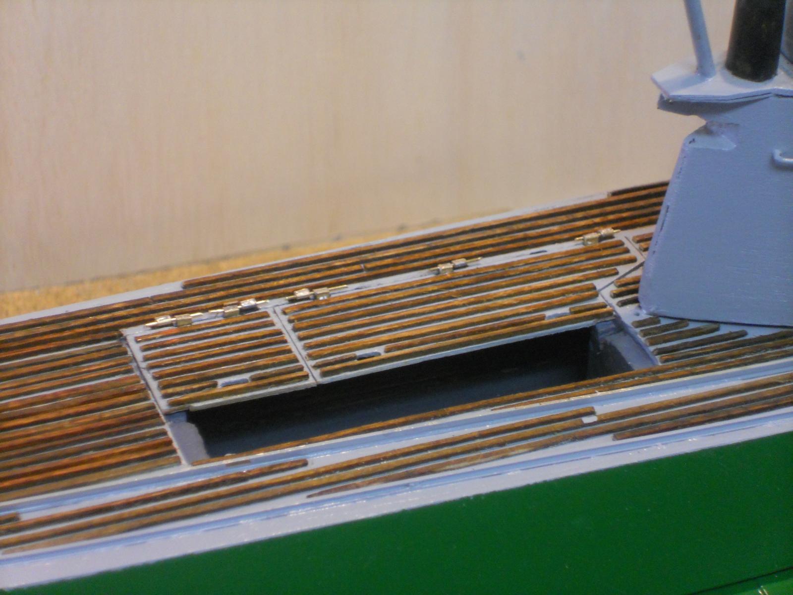
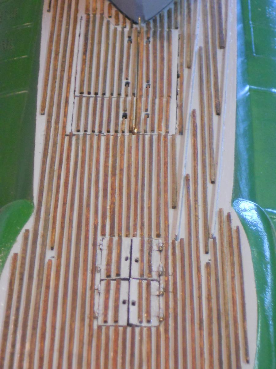
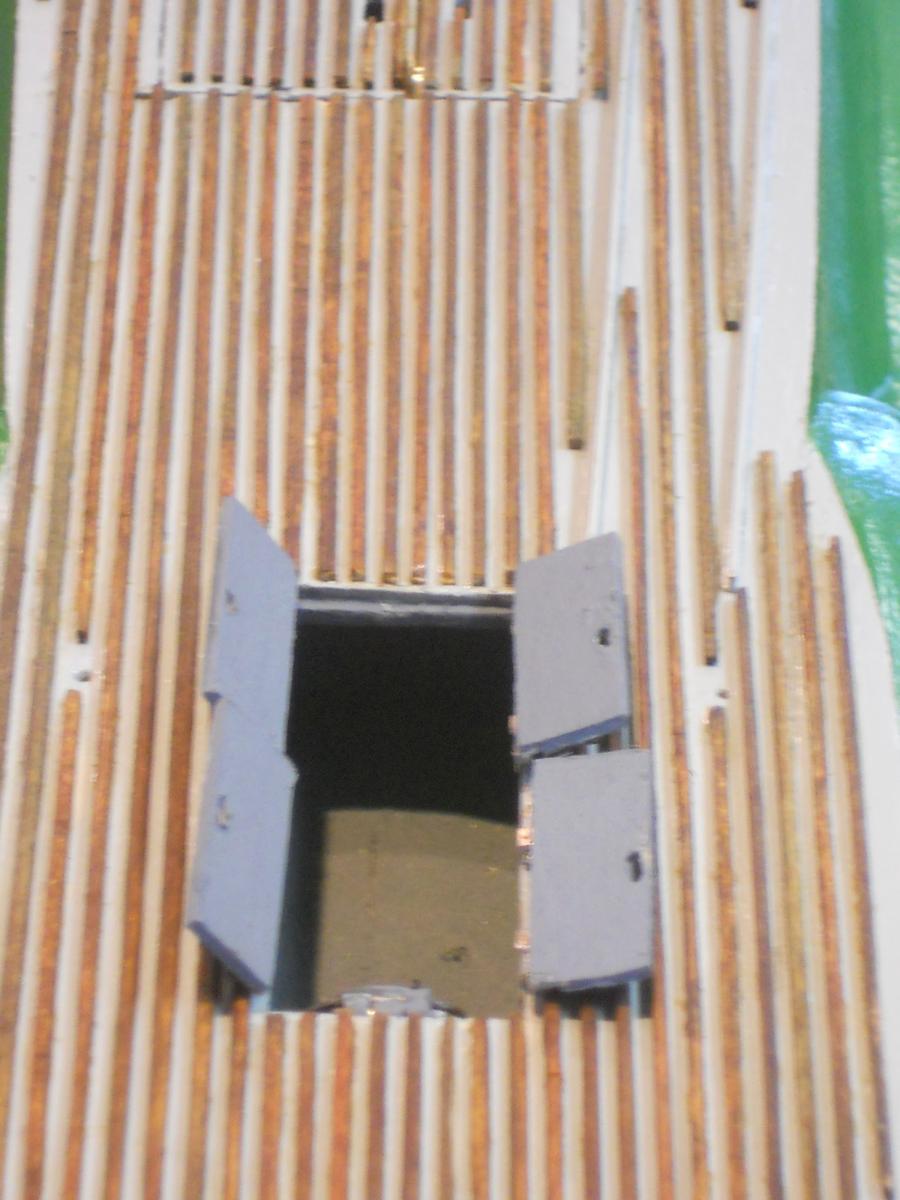
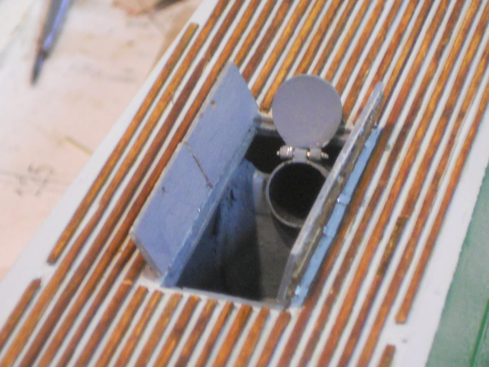
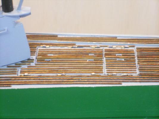
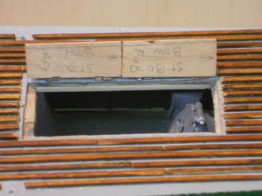
Today I was able to install the starboard dingy hatch doors and gave it one coat of paint on the inside of the doors. I still need to give it one more coat and then touch-up the outside and some needed trimming and futs'n with it, as usual. I always find stuff to tweak here and there. This shows the dingy hatch doors installed and closed seen from the port side. It still needs touching-up paint and some dye for the slats and whatever else I see that needs to be prettied up. This is looking forward and uh oh, what de we see? Ah, I need to to redo the wooden slats on the starboard doors I didn't see it on the model, but does it show up on the pictures though. They need to be toughed up anyway. This shows the hatch doors open with the first coat of interior paint in dark grey. The dingy loading / unloading crane beam acts as the center hatch door support. It'll hinge on a pivotal brace just aft of the conning tower. This is looking forward with a plastic boat acting as a temporary dingy Cheers,
-
Hello everyone and thanks for dropping in and chatting, it's much appreciated. I trust the Admiral served enough refreshments to y'all? I couldn't respond yesterday because the Admiral and I went to pick up her sister Eileen and her husband Sjoerd from the Sandford airport. It made for a long day, we were early, the Dutch airline forgot to tell us that they were still using standard time In any case it was very nice seeing them again and we had a nice visit with them in the hotel when we got to Daytona Beach. Thank you Michael for your approval on the hinges. Tedious work to say the least. Hello Wacko Joe, thanks for dropping in and your kind words. I'll try to keep them pics coming but am afraid that the next two weeks they might be rather slim. Being busy entertaining Gwen's sister and husband. Hoi Jan, Thanks for your approval, it means a lot to me. I'm glad you found a pic of my sister !! She was a year and half older them me and much prettier too as you can see! I do really appreciate the link you included, man . . . I spend quite some time looking at the old pics from the colonies. Nostalgia set in - - - we call those pics "tempo dulu." For us, the colonists, they were really the happy times with fond memories - - - till the Japs spoiled it. Okay, next post I'll add the pics of the finished dingy hatch doors. Talking about pics, I need to check all my posts and see if any are missing. Cheers,
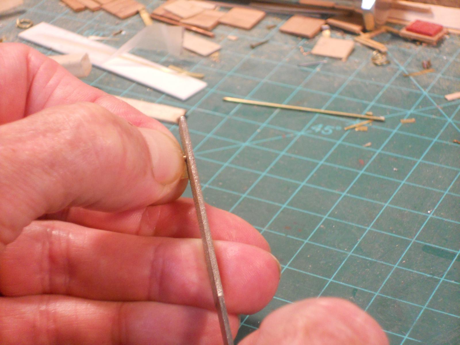
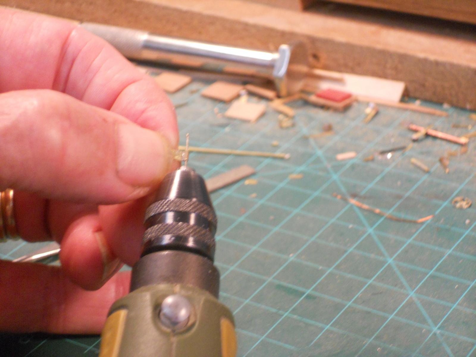
-
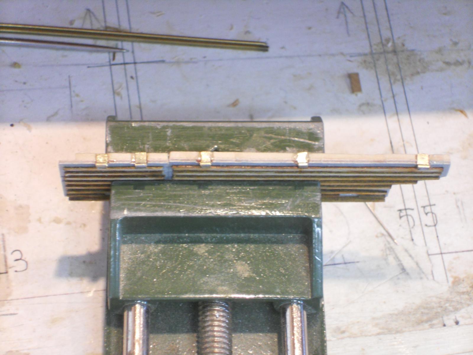
I want to again thank all yuns who visited and clicked "like," much appreciated!! Guess what - - - I found a baby picture of me and thought all yuns would like to gaze at it. Yup, even then I was a happy, handsome little devil Piet's baby picture. Other then that I managed to semi complete the installation of the port side dingy hatch door. Only the hinge pins still need to be shortened and secured and then painted. I have made a start with the starboard side hatch doors and hope to be well on the way with that one too. I most likely won't complete that installation because Gwen and I need to go pick up her sister and husband at the Sandford International Airport. I also need to help her in tidying up the house some more, she has twisted her knee and it's really hurting. I had Gwen take a few pics of me filing the hinges and drilling the holes for yuns to see that I was not kidding. Senior Old Salt says that true sailors do that, hmmmmm, I wonder where I picked up that crazy habit Airplane guys do the same thing. I am also adding a few more pics of the dingy hatch doors on the port side. Self explanatory. You can't see the file resting on my left hand index finger due to the angle of the camera. The admiral is not well adapted to camera's but she tried her best. Self explanatory but don't do this at home This shows half of the hinge assembles cemented to the deck beam port side and I have temporarily shoved a brass rod through all of them to check for alignment. I have also strung the other halves to the rod to check fit with the hatch door installed. Seemed okay. So I went ahead and cemented them on the hatch door, see next pic. This shows the both port side hatch doors in the Proxon vice, this way they won't sag and I used the 5 minute epoxy this time. This pic shows the port side hatch doors installed. I still need to shorten the hinge pins and secure them and finish painting them on the inside. When they are all done and neatly painted and trimmed I'll make the final pics. Cheers,


-
Ahoy SoS, welcome to my shipyard. You think there's hope for me - - - becoming a true sailer???? I'm an airplane guy, I make'm, I break'm, I fix'm and fly'm. My father STRONGLY advised me not to go to sea and so far I have been able to keep my promise. However, besides having high octane and JP5 in my blood I also have some salt water too Cheers,
-
@ John (Lad): Thank you very much for your kind words and for stopping by. She's progressing albeit slowly. @ Vivian: Ah, you're not bad - - - none of us can know everything I only know something about airplanes @ Michael: Thank you Michael for dropping in and your kind words. Well, actually the hinges were a real challenge and i didn't feel bored at all, had to keep my concentration on them little buggers Yeah, I'm going way overboard from my original plan but I'm glad I'm doing it though. @ Doris: What can I say my dear friend, thank you very much for your compliment, coming from you it means a lot. Cheers to all,
-
Wow and a double WOW! Nice work Remco! Cheers,
-
First of all, thanks to the many who visited and clicked the like button, it's very encouraging to me! ! @ Vivian: Thank you for visiting and your compliment, much appreciated. I do also visit your build, looking good! Correction on your nomenclature though - - what you are looking at or actually looking into on pic 4 is not a launcher but a loading tube for torpedoes that'll go into the aft torpedo room. @ Popeye: Thank you !!! Yeah, it worked out okay but I had my doubts when I started making these tiny hinges from 0.5 mm brass tubes. I was afraid I'd burn them all to a crisp. Well, today I continued with the hinges for the dingy (jol) compartment hatch doors. I completed all assemblies and have cemented five on the longitudinal deck beam, port side. I used slow acting 2 part epoxy cement which gave me fits. They kept sagging down and I had to keep going back and forth moving them back up into place. I was afraid that the 5 minute epoxy would not give me enough time to cement the five I needed for each side. I'll find out Sunday if they are holding. CA is just not holding them good enough, they pop off real easy. Y'all may be laughing again but in filing all 20 pieces after soldering the little tubes to the brass strips I actually filed some skin off my left index finger. It's rather sore and I'll give the poor thing some rest As I have mentioned before - - I like to hold parts between my thumb and index finger while filing and drilling small holes and use my finger as a guide. Well, you can only file so much and then the skin is also gone No problem though, our bodies have this build in self repair thing and before I need to file some more stuff it'll be healed and good as new So, no pics for today but I may take one of half the hinge assembly on the port side Sunday. I need it for my own record anyway. I'll ask Gwen if she can take a close-up pic of how I file these little buggers and use a drill bit to clean the burrs. Y'all have a great weekend and happy modeling, Cheers,
-
Hi Robbyn, sorry I'm late to join in following your re-build, I too have been busy and kinda distracted. My prayers are also out on behalf of your mother. I know from persona; experience what's going on in her mind. I am now also undergoing treatment for my second cancer, this time bladder. But things look up and I'm not too concerned. Your build is beginning to look really spiffy and remembering the past errors seems to be helpful. Keep a stiff upper lip and stay in good health. Cheers,
-
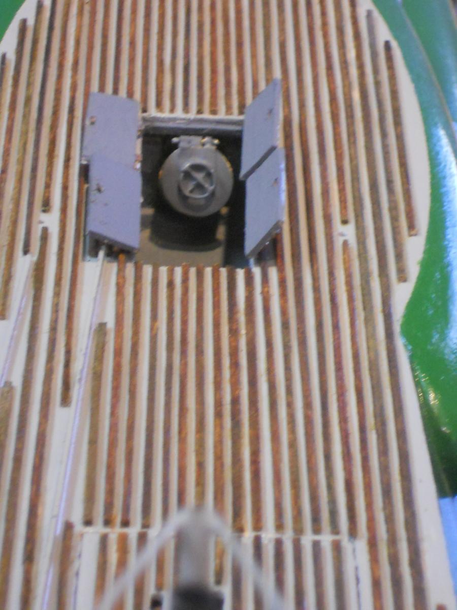
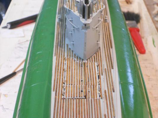
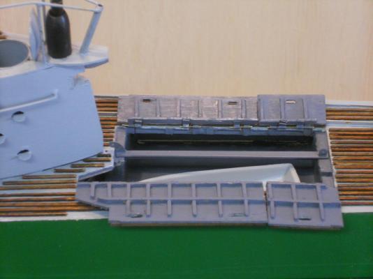
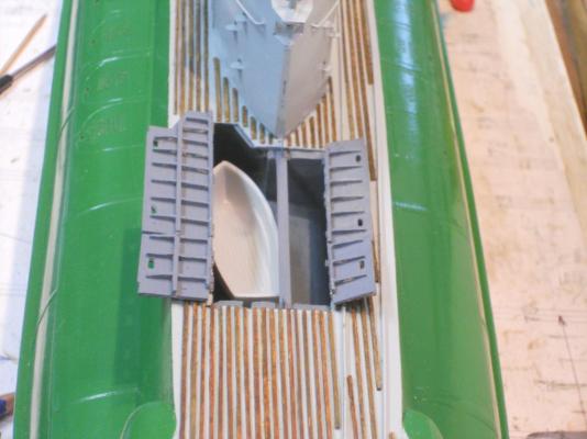
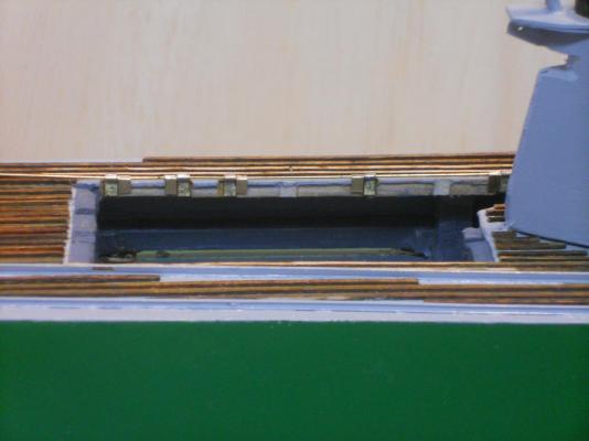
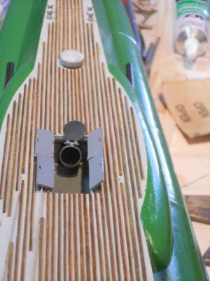
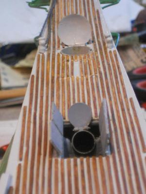
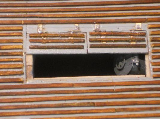
Thanks every one for visiting and your like votes. Well, today was my first of six visits to the urology center for my BCG treatment and everything worked out just great. None of the warned about side effects were encountered, and that's a good thing I managed to spend a few very productive hours in the dockyard this afternoon, aka the garage. I completed the aft torpedo loading hatches and they too worked as advertised May still need some more tweaking and futs'n It was still before 1700 hours and figured, may as well start with the hinges for the dingy hatch doors. Unfortunately I used paper for hinges previously and had to cut a few notches into the side beams. But this may prove a good thing because I am going to use a thicker brass strip for the hinges that'll fit right in and is also sturdier. They will be vertical and the hinge strips will be hidden when the hatches are closed, only the hinge tubes will stick above the deck. This should allow the hatches to lay flat on the deck when opened. I tested cementing a small brass strip to a piece of wood with two part epoxy cement to see how it would hold on the narrow side beams. I appears to be holding okay so I went ahead and started to make ten hinge assemblies, five for each side. I only completed five sets before knocking off because I wanted to help Admiral Gwen with scrubbing the breakfast nook floor. The rollers on the bottom of our chairs are a hard plastic but do slowly disintegrate and leave small particles of black plastic on the porcelain tiles. Sooooohhh, I was making like Cinderella and scrubbed and mopped the floor on hands and knees I did earn my Leffe dark afterwards and Gwen had a glass of wine, she's not a beer drinker. Tomorrow we'll continue with the dingy hatches and hope that my plan for cementing them on the side beams pans out okay. Keep fingers crossed - - - on better thought maybe not, I need them to work on these small buggers Okay, here are a few pics of the completed aft torp loading hatches. This shows the hatches closed and looking forward. Sorry, but I forgot to tuck the hatches down all the way, they do though If anyone is wondering what those curved lines are on the starboard side, those are the tracks for the torpedo loading dolly. The tannish looking lines are the shadow cast by the ceiling lights. The little holes on the outboard sides next to the loading hatches are the location markers for the loading gantry. This shows the hatches in the open position, nicely painted. This too is looking forward. This shows the hatches open and looking aft from the con with the loading tube closed. This picture shows the hatch doors open and looking aft with the torpedo loading tube open, ready to receive a torpedo. That round thingy sticking up out of the deck a little further aft is the emergency telephone for in case the sub is disabled and can't surface. That way they can establish voice communication with the surface rescue folks. Yup, I made that one so I can pull it out, it has a cable attached to it that's stowed below deck. Sorry, the phone isn't working, in case you'd ask Cheers,


-
WOW, what great responses on the "like" votes, thank you all very much. @ Mark T: Thank you very much Mark for your kind words but I see the little things that are not quite right and I thought photos make them so glaring that nobody can miss them Yes, there are a few spots that need to be worked on but that's no problem, all part of the pleasure in modeling. @ John (Texxn5): Well now, I'd better watch out then John @ Remco: Thank you Remco, do I get a gold star now??? @ Popeye: Thank you too Popeye. As with most challenges you either accept them or submit to defeat, I had to give it a shot. It reminds me of several challenges thrown my way in my life and succeeded. Well, I did some more work on hinges today, i.e. this morning. I started to make them for the aft torpedo loading hatches but only got to two pair. For some reason I had more of a problem with these then the front ones but they are done. Twice I heard a "pinnng" when the 2 mm piece of tubing went flying out of my tweezers. Good luck finding them on my, ahum - "busy" work bench. So I had to cut two new pieces and then A third one I couldn't get the pin through so again I had to replace it. Gwen, the Admiral, really wanted me to clean the patio at the back of the house in the screen room. So I got the pressure washer out and spend the rest of the afternoon playing with water. It was fortunately nice and warm today, 26 C Hopefully tomorrow I can make the other two pairs and then removing a few deck slats so I can cement them on. I hope I won't run into any problems with that easy job. Thank you all again for your support! Cheers,
-
Hi Nenad, I agree with #3, it has that nice patina of salt water weathering. # 2 is also nice but more for an as new deck. Cheers,
-
Hi Popeye, sure nice looking crows nests and I'm sure you'll figure out a way to make them look like weathered wood, stain, dye or paint???? And your mizzen seems to have a nice angel too. Cheers,
-
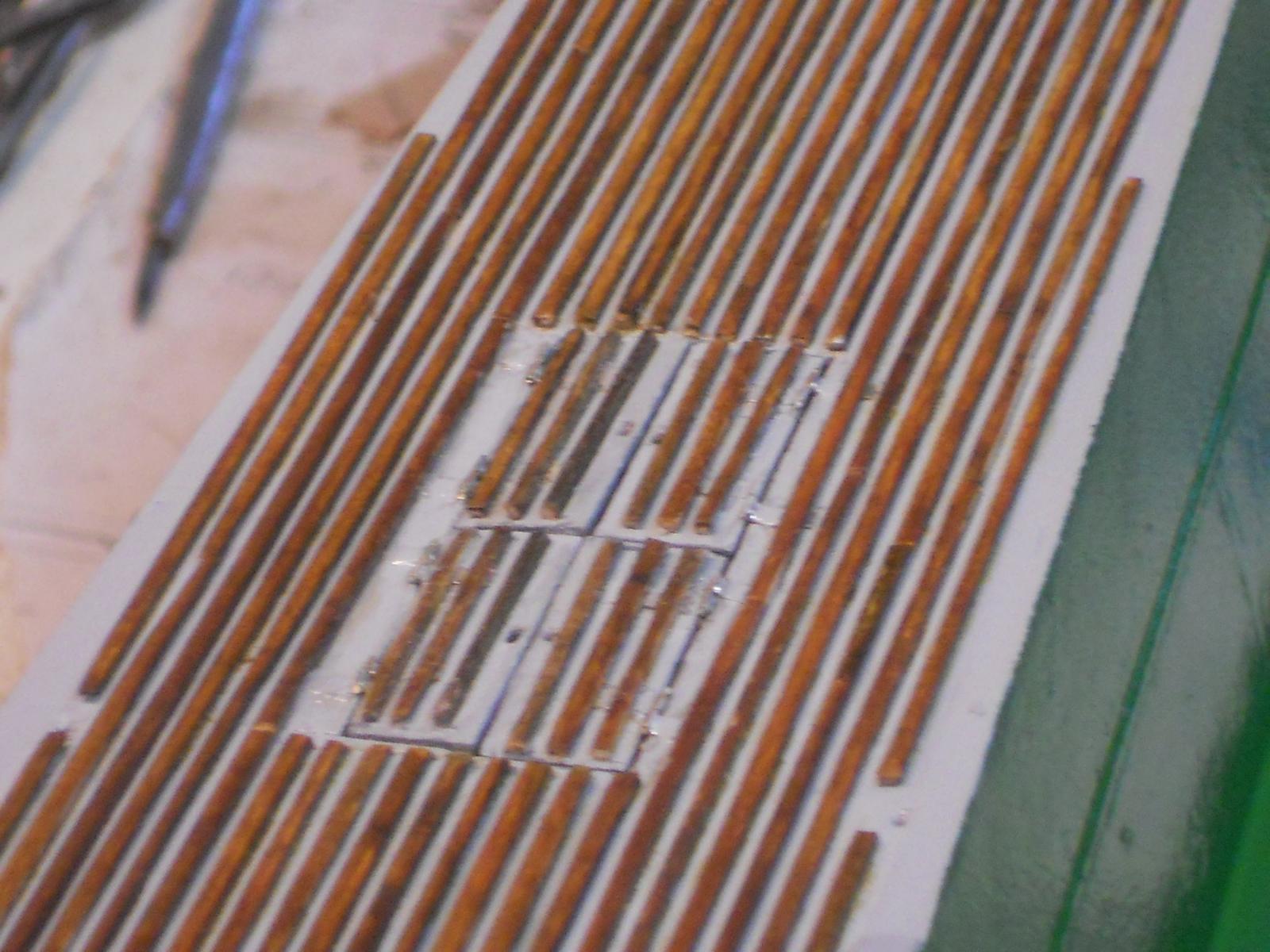
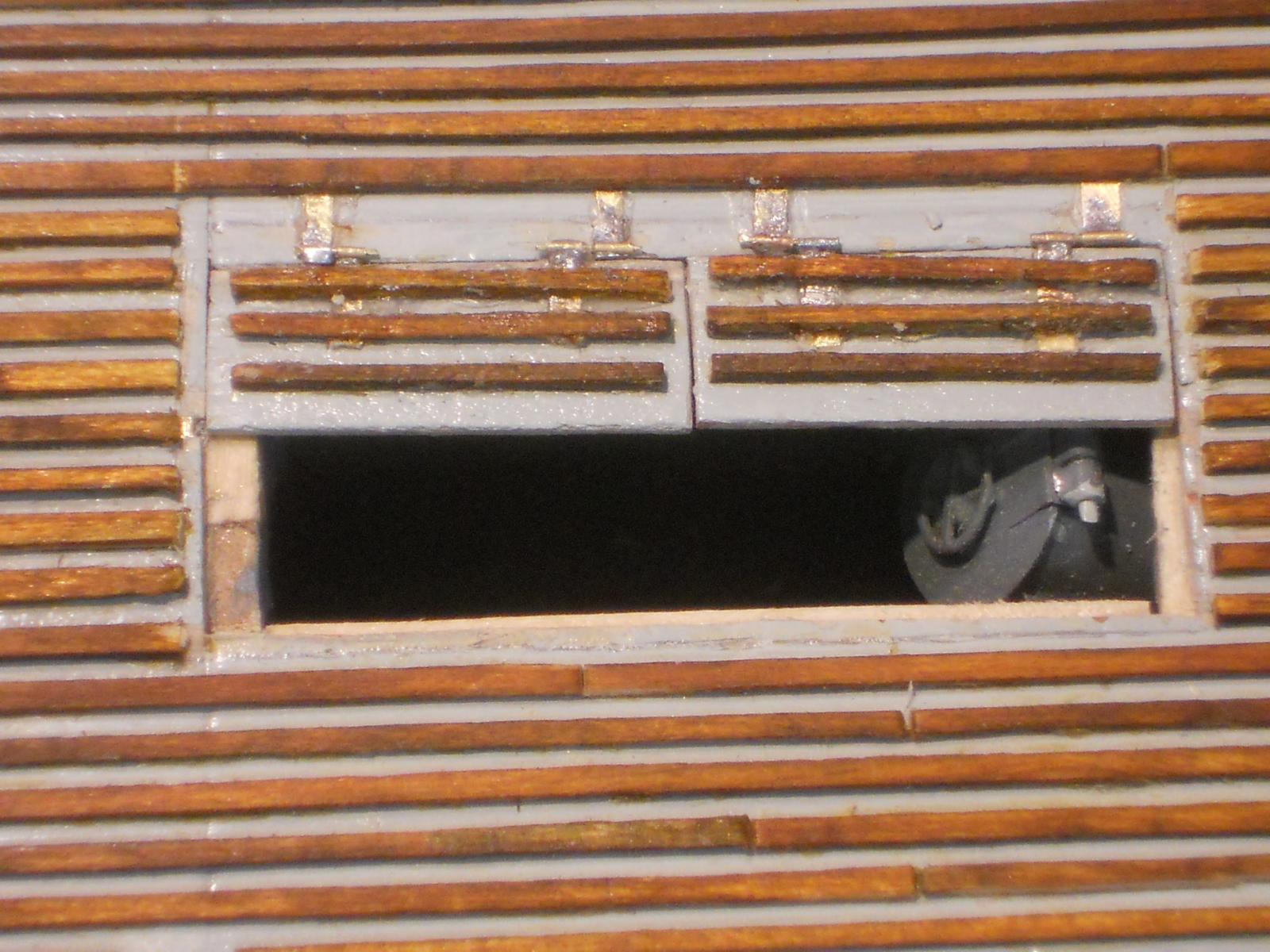
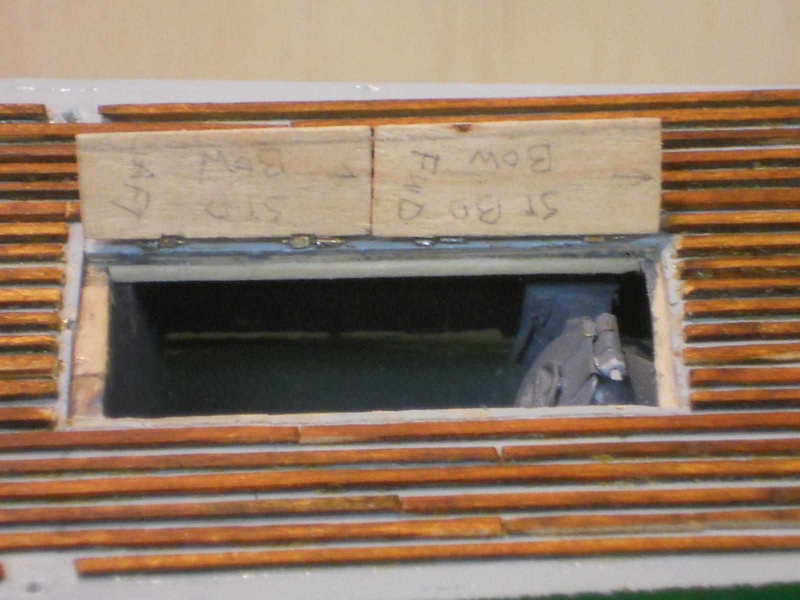
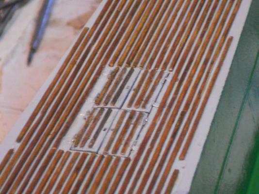
Sooooohhh, I mozied into the shipyard this morning after breakfast and my first fix of coffee to tackle the fwd starboard hinges, for real this time - - - chuckle - - chuckle. This time I made sure I had the 0.5 mm brass tube in my hot little hands before I cut the four needed pieces and that without the optivisor Everything worked as advertised and they looked rather spiffy after they were all dressed and filed to the proper dimensions. I found it easier to remove some of the deck-slats to cement them to the hatch doors and the deck. Then I replaced the deck-slats, and they covered must of the brass strips. Next I touched up the deck-slats with the dye and then touch-up painted the hatches and the deck where it was needed. Then an operational test on the hinges and taking a few pics for the record and for all y'all to see. Ooooh, sorry, a little out of focus but these are the hatches in the closed position. You can see the hinges because I had to cement them on top of the hatches and the deck. On the real boat they were bolted to the sides of the hatches and the deck structure. However, in my case t would not have been strong enough to withstand too many openings and closings, I tried it first with CA and two part epoxy. Also on the real boat there were only two hatch doors but my error here was that the torpedo loading tube was not angled steep enough so I had to make enough room for the torpedo to slide into the loading tube, ergo the four hatch doors. I could have faked it and not even attempt to show the model with a torpedo being loaded. I'll most likely keep futs'n with this to dress it up better. This shows the hatch doors open just as far as they did on the original boat. Remember that this was also an afterthought. Originally I didn't plan on going into this much detail but I'm glad having done so. That piece where the loading tube rests on is a deck frame/bulkhead. On the real boat that was all rather light steel structures that supports the deck and thus also all the other things attached to it. This is a straight on shot forward looking into the torpedo loading tube. Aha, I see a few more deck-slats that need some attention. Now you understand why I keep picking and futs'n at things. But overall I'm very pleased as how she's coming along. With all the futs'n and picking at things she's only getting better look'n. I hope all y'all approve. Cheers, Cheers,

-
Hello everyone and thanks for your like votes on my dumb error but at least we all had a laugh or two, I'm still shaking my head and snickering about it. I should have made a picture of that piece for y'all to see but I dumped so I wouldn't reuse it by mistake. @ Remco: Glad you had a laugh, that was the whole idea. Optivisor - smoptivisor. I don't need no stink'n optivisor, I have perfect vision hmmmm, that's what I like to tell myself. As it is I do wear 3X magnifying glasses and even with them I grabbed the wrong thingy. That would make me domkop squared @ Sjors: Pffffff - - - to you No need for a translation, I think all y'all got the idea and besides, unknown to many but English originated from the Germanic tribes Angels, Saksons, Jutes and Friesians, way back in early CE (AD). And Dutch? Well, it originated from the same tribes, so we are all one happy family @ Mark: Right on Mark - - - pfffff is a perfectly good word - - - in Dutch but we can adopt it. Now "domkop" may be known to the English speakers as "dummkopf" in German. In the US we would be quick to say "dumbshit," DUCK !!! yeah, my mom would hit me over the head when using such bad words So, I'm trying to be a good boy and not use such improper words on this very distinguished forum, so I refrained from using it. Therefore it's "domkop," i.e. dummy, dunce, stupid-head. You want another Dutch word? How about "stommerik?" You are all free to use it - - - there is no copyright on it @ John (texxn5): Yup, back in the shipyard but I had to mow the front lawn after lunch, it looked a little ragged. Thanks for the compliment, the hinges may not be perfect and gold plated because most of it is hidden anyway but the main thing is - - they are functional. Re the mine bun lid hinges - - - I only made one lid to possible open. I am in the process of making a jig for hinges but have not progressed very far with it. Sooooh - - - it is possible that I may figure out a way to make a believable and workable set of hinges. Your sneaky way of putting a challenge to me is duly noted , you are just as bad as Remco with challenges but that makes this hobby the more interesting. I love it. How did you know I was going to have a Leffe dark to celebrate the completion of the hatches? Okay, enough of the levity and back to some serious work, yeah, right - - - if yuns believe that then I have a bridge for sale.
-
Hello everyone, This post is just so that all y'all can have a good laugh on me, at least I did As I started making the hinges for the forward starboard torpedo loading hatches I cut 4 pieces of 2 mm 0.5 brass tubing, or so I thought. I also cut 8 each 1.5 mm strips of 0.1 mm thick brass sheet. Great so far, making good progress. I then proceeded in soldering the 2 mm brass "tubes" to the strips, still working great. I then filed the brass "tubes" to the width of the strips and wanted to de-bur the tubes. Well, I didn't see the holes in them and thought, oh poop, I got some solder inside and started to clean them out with my #80 drill bit in a small hand drill. Hmmmm, not much progress. So I put a #80 bit in my Proxon drill motor. It was slow going because it got real hot quick and burned my fingers. I switched the little bugger to a small pair of pliers and after about 5 minutes I drilled clear through the length of the brass "tube." Great, I thought, that worked - - - never even giving it a second thought - - - hmmmm strange, why so much solder inside the tube - - - well, okaaaaay - - - over to the next one. Well, that one showed the same symptoms and again I started drilling the assumed solder out of the brass "tube' but broke the drill bit. Hmmmm, scratched my head and looked at the assumed brass "tubes" real close under a magnifier. I couldn't believe what I did Okay now all yuns can start laughing - - - Instead of the 0.5 mm brass tube I took a 0.5 mm brass rod that was laying there!!! Needles to say I first slapped myself on the forehead and shouted DOMKOP !! and then laughed myself silly. So what - - - pfffffff while throwing hands up halfway Wow, that's two Dutch words in one post, yuns are so lucky On the positive side, I now know that I can drill a hole through a 0.5 mm brass rod and make a tube out of it Anyone else want to try that? On second thought, perhaps not - - - these cheap Chinese drill bits break real easy. At that time I had to get ready to go to my monthly colored pencil club meeting and planned to correct this embarrassing fiasco later in the pm, which I did without any further mishaps or mistakes. Sooooh - - - hopefully I'll have these two hatch doors done tomorrow and everything dressed and painted nice and on to the aft deck. Hick - - hick - - ha -ha -ha - hick - - hick. Sorry about that, I'm still chuckling about it. Cheers,
-
Hello everyone and thanks for stopping by and all the like votes, it's much appreciated. @ Mark: Just don't move around with your jaw on the floor, you may step on your lower lip and that's a real ouch Thanks for the compliment my friend. Yup, they do work and that makes me a happy camper. @ Remco: Yes it's good to be back in the shipyard but there are still some things that need to be done in and outside the house though. You have really challenged me my friend but I appreciate it - - - after the fact You have more faith in my abilities then I did I really had some misgivings and procrastinated because of it. Hopefully I can do the two on the starboard side tomorrow and then finish it all with paint and touch-up the wood with dye. @ Daniel: Thanks for your kind words. Yes, thin, long fingers and narrow hands. That came in handy working in airplanes but it was really good doing artwork, painting and drawing. Both my eyes are now between 20 / 20 or 25 / 20 - - - after a double cataract replacement, but i still use a 3X magnifier glasses though. Actually, I measured the brass tubes and they mike out at 0.45 mm @ Popeye: Thanks Popeye, you are too kind - - - but I take it Well, I expected them to work, after all, when you stick a rod into a tube they should move, right? Oh, I guess i could make the hinges a little narrower but not by much so they would be a closer to scale. I'll stick with the 1.5 mm wide strips though for ease of handling. When they are painted you won't notice them too much anyhow. This morning I had to trouble shoot the fax part of my HP all in one. It would not receive faxes and spend scratching my head most of the morning. I hope I fixed it by resetting it to auto answer. Now I'll have to ask daughter to send me a test fax. This afternoon I spend cleaning up those two hatch doors. I replaced one of the slats on the forward door and removed some of the CA cement. This still needs to be stained and the rest painted. Well, actually this hinge making project worked better then I thought. I was really apprehensive at first and thought, no way can these tiny tubes be soldered. But then after they were done I just said "pfffffff," no sweat baby with a grin. The hardest part is holden these little parts together but I figured out a way. I first "tinned" the end of the brass strips, then put some solder paste on it so the 2 mm piece of tubing will stick to it. Then holding it down with a toothpick applied the heat and bingo. Then filing them down to fit the strips and de-bur the holes caused from the filing. The final shaping was the most difficult part, holding it between my fingers. Okay, that's all she wrote for tonight. Y'all have a great weekend and happy modeling. Cheers,
-
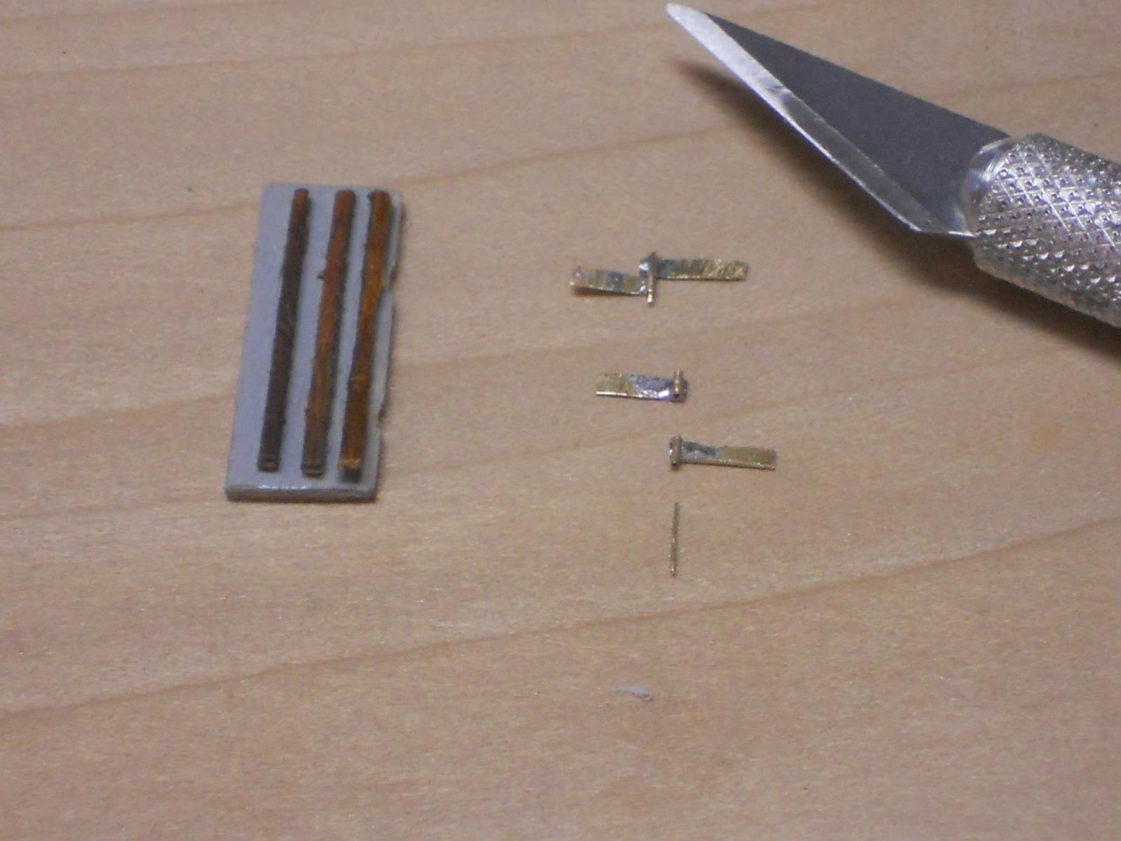
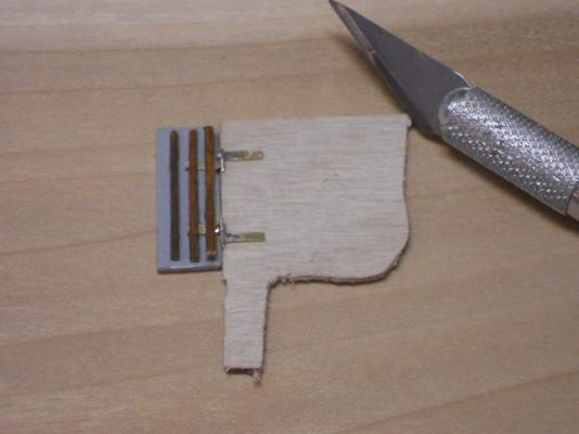
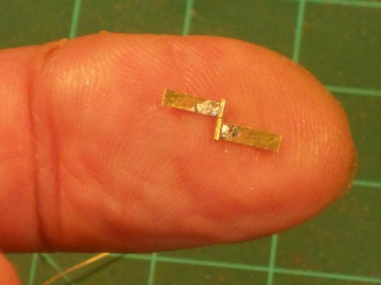
A heartfelt thanks to everyone for your best wishes and prayers and all your like votes. What a fantastic group this is! Today was de first day back in the shipyard after doing a lot of research on this cancer thing and alternative protocols to help my bod's immune system. I have a long list of stuff to get, but now is the time to divert my attention to my father's boat. Thanks to those who gave me advice via PM's. I mentioned to Remco in a PM that I most likely will be making the hinges for the torpedo loading hatches. If I don't finish things in the deck area then they'll be in the way when doing the gantries. I could of course also start with the deck gun and props but I thought to try making the hinges with the 0.5 mm brass tubes Remco send. This'll be a real challenge because of the minuteness of them. I cut strips of 0.1 mm brass sheet into strips of 1.5 mm of undetermined length to be trimmed to size on the boat. I cut the tube into 2 mm lengths and silver soldered them to the brass strips and trimmed them. Now I had to de-burr the holes to allow the 0.1 brass rods to enter, very tedious work, to say the least. Fortunately my hands remained rock stable and everything worked as advertised. I also had to de-burr the rod ends because of snipping them with my mini side cutters. I just hauled my rifler over them and then finished with 400 whet or dry sandpaper. worked like a charm. I next "worried" slots under the deck slats on the hatches to slide the hinges under them. This gives me some extra material for the CA to grab on. A few of the slats I did remove for access though. I made only 4 hinge assemblies today in about 6 hours time, which was enough for the two hatches on the port side. That was enough for today because I was getting bleary eyed and needed to take an eye break for today. Hmmmm, yeah right and then behind the computer to check my mail, the news, writing friends and on MSW. Okay, I have taken a few pictures of today's work so you can get an idea how tiny these things are and even at that they are still too large for scale, I think. What you see on the pics is still in the crude undressed state so please hold the rotten tomatoes This picture shows the aft port side hatch with the hinge assemblies. There two hatches for port and 2 for starboard for a total of four. The same holds for the aft torpedo loading hatches. I temporarily assembled one hinge because it still needs some trimming. The other I left in an "exploded view." Now just picture me holding these little buggers in my left hand when dressing and trimming them. I found that holding them in duckbill pliers didn't give me the visual of how much I had filed away so I held them between thumb and index finger. This shows both hinges temporarily mounted and laid in top of a scrap piece of 1 mm deck plywood. Everything needs to be dressed and trimmed yet. The Exacto # 11 blade should give a measure of scale. Well, I thought to put one hinge assembly on my finger and show you how small they really are. Perhaps you can see a cut in my finger on the left. That's where I cut it scraping some CA off but accidentally held the Exacto # 11 on an angle instead of straight, ouch. Bandaid time. Here we see both the port hatches temporarily put into place. There is still some more fixing to do, like replacing two deck slats and after they are all cemented to the deck another deck slat over the ones on the deck. Yea, these close-ups show a lot but everything will be neated-up. Here they are shown in the open position, ready to load torpedoes. I'll wait with the final painting till the starboard side is completed. Cheers,

-
Fantastic Boris!!! You have done good Cheers,