Piet
-
Posts
3,568 -
Joined
-
Last visited
Content Type
Profiles
Forums
Gallery
Events
Everything posted by Piet
-
 Hey Daniel, champagne on a Dutch sub??? It'll be more like Heineken my friend It used to be that when they launched a ship or boat they would hoist up a broom to the tallest mast. That was a sign to sweep the seas clean of the enemy. Well, she'll have a few flags and pendants on her alright but I don't know about the Flying Dutchman flag, I'll have to invent one Cheers,
 -
Hello all and thanks for dropping by, much appreciated - - - especially your like votes. Ah shucks John, you make me blush - - - but thanks anyway, I'll take the compliment I could have hammered the errand ring into shape on a round steel bar but it was too fat. The thinner wire worked easier too. Hope to be able to finish the steering wheel tomorrow so I can paint the cockpit and put everything together. Y'all have a great rest of the evening and see y'all tomorrow. Cheers,
-
Interesting dialog! You can always dream up a likable story, like - - - they had problems with making the "new" Brodie stove, like problems with the moulds, poor iron alloy, poor casting, all that making delivery late. So the Navy just told the shipwright, we can't wait any longer, so go ahead and build the brick hearth - - - we'll replace it later when Brodie has got their act together I'm sure that a brick hearth will add a lot of interest and charm to he model. You can weather it nicely with smoke stains, grease splatters, a spit, big iron cauldrons, iron hardware, etc. Hmmmm, you can also add the cook We can dream, but that's the fun part of these projects. Cheers,
-
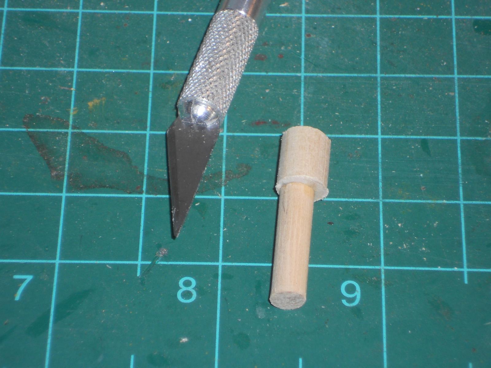
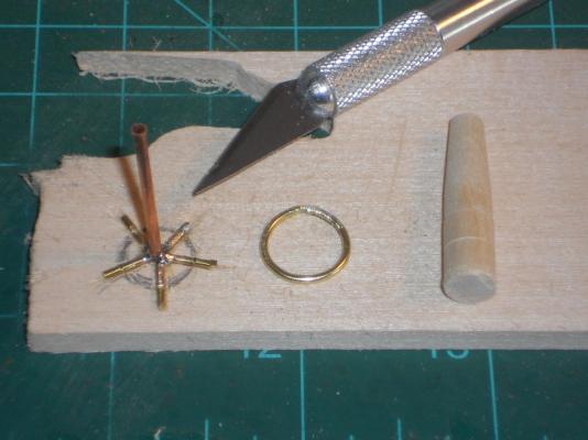
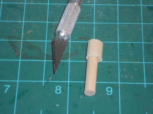
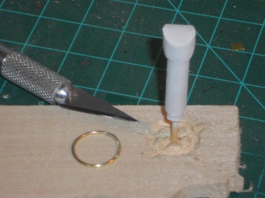
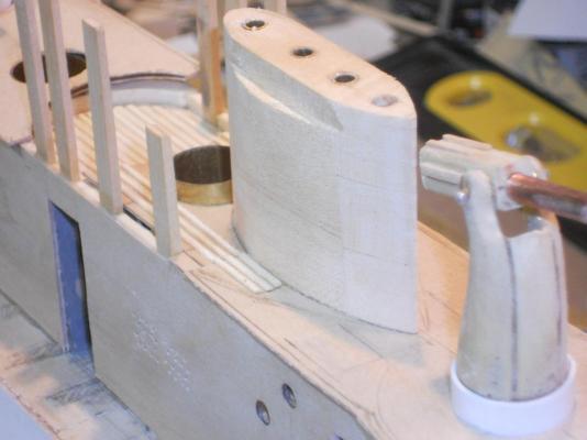
The temps dropped dramatically here in Palm Coast, Florida, down to 50 F or 10 C. Brrrr, but I put on a heavy jacket over a heavy woolen shirt and braved it anyway to spend time in the garage. Hmmm, what did I do - - - oh yeah, I turned the steering wheel or tiller pedestal on the lathe and started to make the binnacle on its pedestal. I also made the provisions for the forward deck light in the front plate of the cockpit and the reenforcing for the front shield of the bridge. For that I made two 1 ½ mm strips of poplar, soaked them in hot water for a while and then clamped them to the front of the bridge to shape them into a half circle. When they were dry I glued them on. The outside one needs to be shaped into a quarter round for "good looks." I also started with making the steering wheel, as they call it, but used a too heavy diameter brass rod, 1 mm. When I started to solder the spokes to it I didn't like the results, much to heavy and out of scale. Besides, the ring is not round, booo on me. So I started to remake it with thinner brass rod, ½ mm, much nicer! I'm using a 1 ½ mm copper tube for the hub and need to make a new jig to solder everything together. That 1 ½ mm piece of tubing may also be to large but the ½ mm tube Santa brought is too small. I do have an idea though to solve this dilemma I'll have to give my idea a try first, tomorrow. This may not look like a lot of work accomplished but I had to make two bamboo pins to anchor the compass pedestal and the steering wheel pedestal into the cockpit deck. Chisel small sections of deck slats away where the compass and steering wheel pedestals are to be glued. Then carve the binnacle into shape to make it look like a compass binnacle and the remake of the steering wheel. All these little things seem to take a lot of time. The brass rod was shaped on this 10 mm dowel, the rod is 1 mm. Not impressed. As you can see that brass tube for the hub is also much too big. Hmmmm, the old machinist's wheels are turning This is the binnacle on its pedestal in the raw state. Here is the binnacle all shaped with its anchoring pin and in the primer with the new steering wheel. Much better this time, I think I'll keep it Cheers,
-
Thank you all for visiting and liking my work, appreciate it very much. @ Adriaan: Welcome back to Oz and happy New Year! Yeah, I have been working while you were gallivanting around the globe Hope to see some progress with your GF. @ John: Hi John and thanks for dropping in. @ Daniel: Happy New Year to you too. Thanks for your kind words and no, the "cockpit" as I call it, it's actually the bridge, doesn't get covered. There is a small shield over the very front of it with a windscreen like structure on top of it, just like the old cars used to have. That has me a little bit in a quandary but I think I found a way to do it. They did use canvas canopies over the bridge area as well as over the decks to give the crew some shade while in the tropics. You'll just have come back so once in a while to see how it all looks like. @ Popeye: Thanks Popeye for taken the time and interest in my build. Talking about moving right along, you are no slouch either with your projects Cheers to everyone,
-
ROYAL CAROLINE 1749 by Doris - 1:40 - CARD
Piet replied to DORIS's topic in - Build logs for subjects built 1501 - 1750
Lovely Doris, the only word I can find to convey the feeling of what I observe in the photos is "Rubenesque." It reminds me of the paintings of Rubens, warm and sweet. Cheers,- 883 replies
-
- 2
-

-
- royal caroline
- ship of the line
- (and 1 more)
-
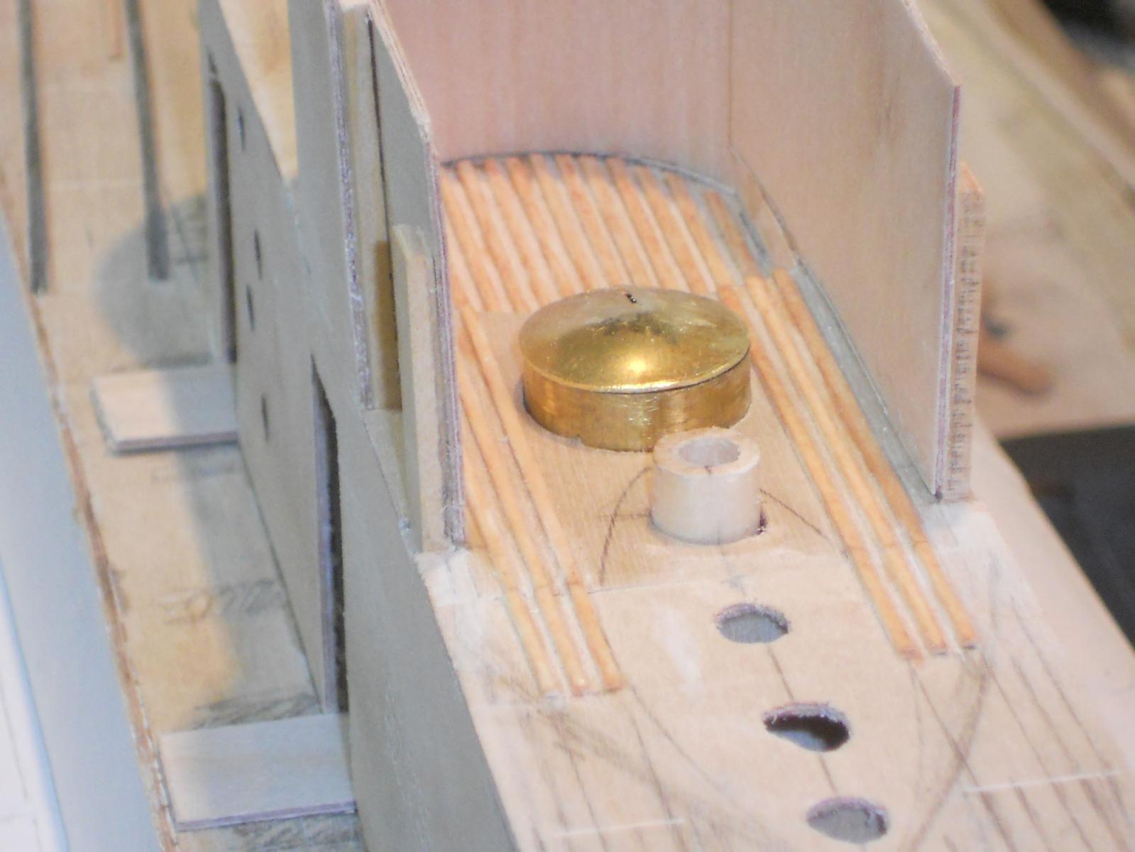
Thank you everyone for dropping in and your like votes. First thing this morning was checking again how my test piece is working out. I had enough time for the glue to cure and it seems to be holding just fine. I didn't really pry to hard, there was no need for that but did use some firm pressure with my fingers and it didn't budge. I found a 00005 sable brush in my collection of good artist brushes and decided to try to paint between the slats on the bridge. That worked like a charm, still have a steady hand I also decided to keep the slats on and mixed some Minwax oak with maple dye that came pretty close to the color I ordered from Fiebing, thanks to Remco for the URL. I also painted both the front and read gun decks and the aft part of the bridge inner liner. I still need to add a lot of stuff in the front part before I can finish painting the bridge. I'll have to wait for the dye to arrive before I can put the deck slats on the gun decks. But that's okay, I have plenty other things to do to keep me occupied. I primed and painted the periscope housing and when the paint had dried I glued it to the con as well as the chart locker to the front of the cockpit. Next I cut a few small pieces of copper tube for the center hinges on the crew hatches and soldered them on. The last thing I did was to trim the aft outer plates to the correct shape for the bridge, painted them on the inside and glued them on. Well, that was all for today and again a few pics of today's efforts. This shows a close-up of the cockpit with the deck painted grey, the slats dyed with my mixture to simulate teak and the periscope housing glued to the con structure. This is another view a little further aft for an overall shot of the bridge. The flash of the camera kinda washed out the grey paint but it really looks nice, much better then the dark grey I had. The aft outboard side panels glued on. I had to use gel CA glue for the aft joint, no way to clamp it there. Cheers,
-
Thank you John - - yup, she's coming along slowly but surely Thanks Remco for the URL for the dye, I have immediately ordered a bottle. They don't have teak but Gwen and I think that Russet comes close, at least close enough for government work and you'll never notice the difference from 10.000 feet Now I can stain all the deck slats before gluing them up, that'll really speed things up quite a lot. Much appreciated for your help Cheers,
-
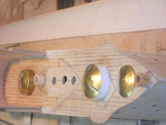
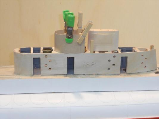
Spend some time today prepping some scrap wood for gluing the deck slats to a painted surface. I had a rattle can of RustOleum primer that was dark grey and a rattle can of RustOleum enamel in light grey. The poplar strip to the dark grey primer seems to hold pretty good but not so good to the enamel. Found out that I used a different wood that was very hard so I tried again with poplar, the same wood as I intend to use on the model. So far both seem to hold pretty well but I favor the lighter grey though. Only problem is that it is glossy. Fortunately the decks are all flat and can use sand paper on it to dull it but most is hidden anyway by the slats. So, it looks like i'll be gluing the slats to the paint. While the glue for test strips were curing I started to make the brass lids for the crew hatches and the AA gun hatches. That's 5 total. They turned out great but I had to do some final hammering to the two larger ones for the gun buns. The die I made from an oak dowel was just a tad too small so the edges for about 2 mm didn't follow the dome curve. No problem though, with a little gentle persuasion with a small hammer on the male part of the die they took a nice shape. So they are now ready for the hinges. I also made the three doors on the port side of the con. They too are ready to be finished. They need some stiffening on the backside though and then the hinges and latches. I am in the process of making the chart locker and the antenna bracing bridge that's mounted to the bridge/cockpit sides, also looking good. So, all in all a productive day. Now I need to carefully put some of the lighter grey between the slats I already glued to the bridge deck but I doubt that'll work without touching the dyed slats. I may just rip them out and start over again. The poplar seems not to take up the dye too well, wonder why. Could be some glue residue on top but I sanded them after the glue had set. Hmmm, may need to find some teak water based dye, right Remco? I really would like to finish the gun decks and bridge area so I can put the hinges on the hatch and bun lids, that'll get me closer to finishing the con. Here are a few pics of todays work. This shows the con with the lids and three doors. They are all just loosely laid on the tubes and the doors are propped against the opening. It's difficult to see the inner liner of the bridge on this picture but it'll show better in some of the following ones. The white styrene will be hidden by the brass hinge arrangement I have to make. This shows the inner liner of the bridge better. I had to cut an opening in the sides for the antenna brace. Another thing I forgot but it worked out okay. Another view of the bridge where you can see the inner liner and the stained deck slats. I'll need a 000005 brush to get between the slats to put the grey paint on the deck This is a close-up of the cockpit. You'll have to cock your head 90 degrees though, sorry about that. In order to make the dome shapes with my die you have to cut a very narrow pie shape out of the circular plug otherwise it'll curl up at the edges. In making a dome like this the outside circumference becomes smaller. This is the last pic I took before knocking off this evening. The chart locker sits on the gun bun, I just glued the bottom braces to it. The antenna brace is made and just stuck in place. I made the top tube oval by pressing it in the vice. The ship's bell also hangs from it. Hmmm, I have to make a tiny bell now I mean it's tiny, perhaps I'll buy one meant for a charm bracelet Well, that's it for today Cheers,


-
Thans to everyone for visiting and your "like" votes, much appreciated. @ Kevin: Thank you and we wish you and yours also a very good and healthy new year. I'm following your Bismarck build, looks awesome! @ John: Thanks John, it's a long arduous road though. Cheers,
-
Hey Boris, now that's FUNNY!!! Did you draw the picture?? Have a very good 2014 in good health and prosperity. Cheers from your Dutch American friend,
-
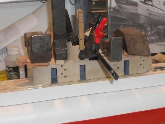
Okay, it's New Year's eve and this'll be my last post in 2013, here's to all y'all Now that the bridge is planked I decided to go ahead with gluing the side panels on. It'll be a little difficult painting and staining the deck but I'll use a small brush I was busy ripping the 1 X 1 mm strips of poplar and sanding them. I only want enough to do the AA gun decks. Bothe the forward and rear decks are now glued on and we can proceed with installing the slats. But first I'll check to see how the glue will hold on paint with some small voids in the paint for the glue to hold to wood. In the meantime I can make the other stuff that goes into the cockpit like the chart locker, the helm, power telegraph, antenna bridge, three doors, hinges for the crew hatch lids and the AA gun bun lids, etc. etc. I can also fiddle with the gun pedestals to add some "stuff" to them. And make more slats for the main deck. So I have plenty of little things to do before getting back to the deck slats. Well, here are a few pics of the progress this day. The front part of the bridge and the forward and rear gun decks are being glued on. I used my riveting bucking bars as hold-down weights. These are still left over from my aircraft sheet metal days in a previous life . After the glue had cured sufficiently I could remove the weights and clamps and just wanted to see how the next side plates would look. Not too bad These are the 1 X 1 mm slats ready for use on the gun decks. Cheers,
-
Hello all y'all, thanks for visiting and liking my progress @ John (Lad): Well, I'm close up to the model and can see all the little blemishes but so far there aren't many, which makes me feel good. Some do-overs to make it right in the process. @ Augie: Now that's an idea and yes, that'll increase the tedious work alright. I'll still be at it till the end of next year I'll have to experiment some first. @ Mark: Thanks for the applause That brings a smile to my face. @ Freek: Yes, I know you went through that routine with your RC KCVIII. I understand that there is no stress on the slats and no one will be handling it, so in theory I shouldn't worry that these slats fall off. Like I mentioned above to Augie, I'll do some experimenting. @ John (Texxn5): Thanks John for your comment. Yes indeed, 2014 will be humdinger and we wish you and Diane also a very healthy and prosperous 2014. @ Popeye: Thank you and I'm also looking forward to getting her close to completion. @ Boris: Now that is funny! I can see that captain drumming his fingers on the rail and telling Moses, "Ok Moses, now what?" That cartoon is a keeper! To all - - - a very happy, safe and healthy 2014.
-
ROYAL CAROLINE 1749 by Doris - 1:40 - CARD
Piet replied to DORIS's topic in - Build logs for subjects built 1501 - 1750
Dear Doris, Thank you so very much for sharing your rare gift with us lesser mortals. Your work is in a class of it's own and on a par with the likes of Rubens, Vermeer, Bruegel, Michael Angelo and Rembrandt. It's beyond words to express myself. I am assuming that will make the cabin roof removable so people can enjoy seeing your exquisite work. Cheers,- 883 replies
-
- 5
-
-
- royal caroline
- ship of the line
- (and 1 more)
-
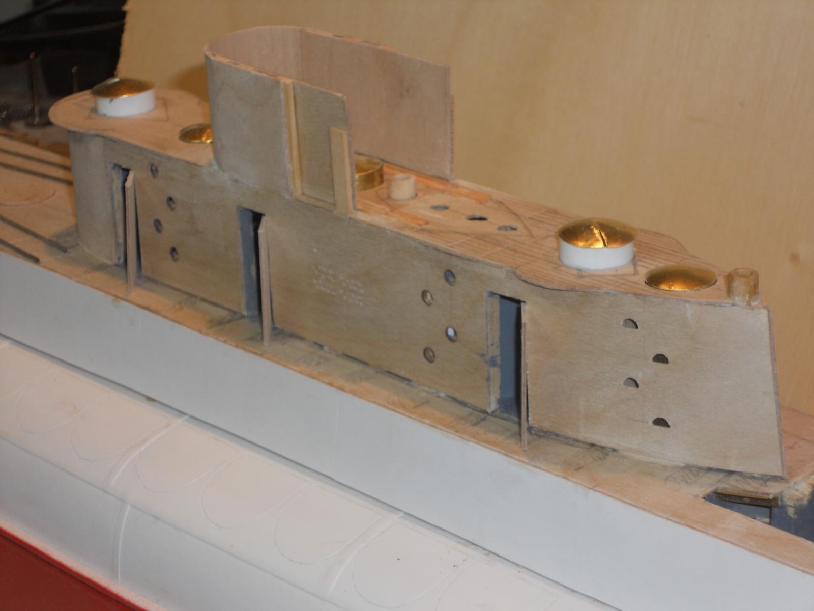
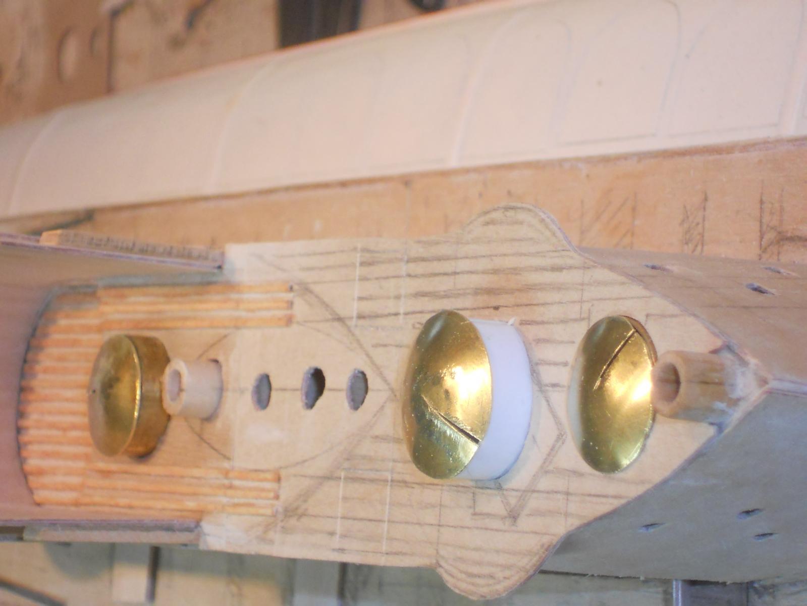
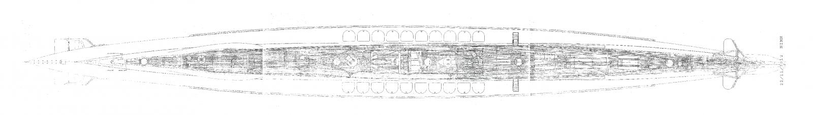
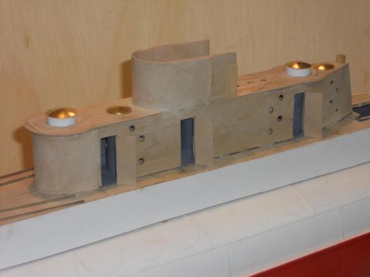
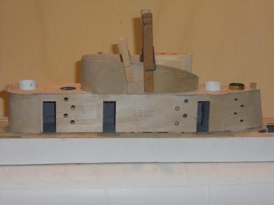
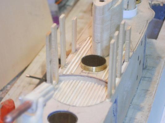
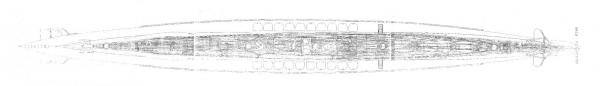
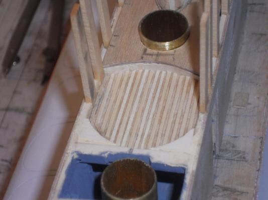
Thank you all for visiting and like what I'm doing! It's really encouraging to me. Today I made some saw dust. I started to rip 1mm planks out of some discarded pieces of poplar. Waste now want not, right? Must be the frugal Dutchman in me I guess that for the main deck I'll need to buy a new ¼ inch board or two from the Home Depot. I'm aiming right now to get the entire conning tower put together so I can concentrate on the deck details. Lots of work there. Yeah, it's a little labor intensive work to make a gezillion slats but right now I have no other choice. I cleaned up the slats in the cockpit and they came out rather nice. I made the slats for the aft end of the bridge planning to install the sides but I'll have to hold off doing that till I have pre-made some of the detail stuff in the front. Next on the agenda is to finish the aft and forward AA gun decks so I can put the deck slats on them. I made the forward AA gun deck plate and cemented the AA gun buns to the frame. I could glue all the deck pieces to the lower con frame but before I do that I must remember to paint the white styrene AA gun buns gray and trim the deck plates. That'll be a chore for tomorrow. It's better to glue the slats to the decks when on the model because then I have the gun buns and the crew hatches as a guide to where to glue these slats. I'm following the deck layout drawing that shows the location of the teak deck slats. This shows all deck pieces fitted but not yet trimmed to their final shape. I'll wait with that till they are glued on. It's perhaps a little hard to see but I have glued a few slats to the deck between the cockpit and the periscope housing. That area will fall inside the bridge side panels. I just stuck the Vickers AA guns in for the heck of it And that reminds me of making a slight mod to the pedestals so I can add some details to them, they kinda look naked This is a better view to see the slats I glued on this afternoon, yup, tedious work alright but it's quite satisfactory to me. Hmmmm, been thinking how to paint the deck and not the slats - - - I would like to stain the slats Gluing them to a painted surface is not a good idea. Here is another view looking forward. You can see a faint outline in pencil where the bridge side panel will come. This is the original deck layout that I'm trying to follow as best as I can. The quality is not the greatest but we'll muddle through it. Right now I'm not that anal about getting the precise number of deck slats correct. So far though it seems to be working out just as the drawing show. It should, because 1 mm is in scale for 5 cm, which is my guess they may have been originally. This is just a profile shot as the con looked at the time I closed the shipyard at 17:30. I'm pretty happy with how it's looking Cheers,


-
Looking very nice Sjors! We, the Admiral Gwen and I, wish for you and Anja a very good, healthy and prosperous 2014. I'll be watching your progress. Cheers,
- 1,873 replies
-
- 1
-
-
- occre
- san ildefonso
- (and 1 more)
-
Hello Mark and Anthony, thanks for dropping in and liking my progress. Wow, you guys are quick ! Don't know how quick I can make the next series of slats so there may be a delay in progress pics Cheers,
-
Hello all and thank you for visiting and your like votes. Today was a bit frustrating. I tried to cut 1 X 1 mm styrene strips for the deck slats but no matter how hard I tried I couldn't get anywhere with it. They keep curling and refusing to remain straight. I gave up and went to making 1 X 1 mm wood strips. Yeah I know, it's more labor intensive but the end result was quite satisfactory. I'll have to go into mass production when it comes time to do the main deck Actually, it goes rather swift once I have 1 mm planks cut. It's then a matter of sanding it smooth and by that time it's about 0. 8 mm, which actually looks a bit nicer. Then carefully cut the 1 mm strips from it a little over size so I can sand them smooth on the cut sides. I made a few strips to plank the small recessed deck of the cockpit and it came out rather well, just a little cleaning up. I also had to remake the aft AA gun deck. I forgot to the side overhang to allow for the gun operation. Oh well, such is life. Got to thinking about those dumb deck slats and didn't pay attention. At least it's a good excuse and I'm sticking with it Wont do that with the front gun deck though I'm running low on plywood. So, tomorrow is making the deck slats for the aft gun deck - - - after I come back from the dentist. We are going to get the stitches taken out and an impression made for the two crowns - - - yippee! The .8 X 1 mm slats are glued on to the deck in the cockpit or bridge. Yes, it still needs to be cleaned up some. The few rough spots in the front will be removed because the help post will be placed there. In the starboard front are a few cabinets and some "stuff" on the port side. That area is also covered with a weather shield so most of the forward slats will not even be visible. This is a close-up view of the slats. This shows the aft AA gun deck with the overhang I forgot with my first try. The overhang will have a 1 mm reinforcing strip glued to the underside as well as metal support braces. The area with the vertical supports will have an inner lining, that's why I left decking out between the verticals. The outside plating will cover it nicely. The periscope housing is not glued on yet, first the slats to be glued to the deck plates Cheers,


-
Thanks to everyone who have visited my build, you know who you are, and also thanks for your like votes. @ Remco: thank you my friend for visiting. Yes, that 1 mm ply bends okay but this is about as small a curve it'll take. Both the top and bottom ends need support and that's what I was concerned about, the top end that is. I'll be using good PVA glue for that. The inside of the bridge is also plated, that'll give it extra support. I'm no longer worried @ Popeye: Yeah, I need to keep in mind to do things now in such a way that won't interfere with the next step. That's why the planking must come first. The crew hatch tube on the bridge, actually all the crew hatch tubes, are kept removable. That way I can solder the hinges on them on the bench. The styrene AA gun bins are out in the open and their pressure lids and hinges can also be made ahead of time. Well, I like to think that my dad would like what I'm doing if he could see it, I do my best @ John (Texxn5): Thanks John, Yeah, you can't beat me away from the shipyard but I took time off today for other things. She's slowly coming together but, as you now also know, these small detail items have tendency to eat up a lot of time. @ Daniel: Thank you for looking in and your kind words. Yup, all those pipes will disappear from sight when all's done, except for the lids. Cheers to all
-
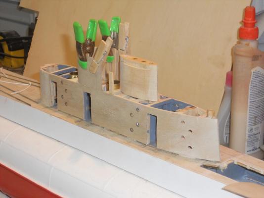
Thanks to everyone for dropping in and your "likes." Accomplished a few more things today. I finished the periscope pressure seal housing, and lucked-out that all the holes lined up with the ones in the pressure hull and all the way down to the keel, wonders will never cease. I had to remake the front piece for the cockpit and the second one worked out fine. A dry fit was great, it seems to be strong enough and is also perfectly vertical to the waterline. I guess that was the aim. All my concerns were for naught, fortunately. Before I can put this all together I have to first make all the deck pieces because the styrene deck slats need to be cemented on it first. That'll be a job and a half. I tried to cut the 1 mm wide slats with an office paper cutter but that may not work too well. It tends to pull the styrene into the blade as I progress further down. No way to hold it from slipping, may think of a clamping arrangement or another way like clamping the styrene under a steel straightedge and using a sharp utility knife. 1 mm is scale but I may have to go a smidgin wider, it's rather difficult to cut these narrow strips. It also has a tendency to curl. Once the deck pieces are made I can then cement the styrene strips to them on the bench rather then on the model, a lot easier that way. This'll take some time I'm afraid but it has to be done and they'll have to painted as well before gluing them to the lower con. I cemented guide tubes in the periscope pressure sealing housing for the antenna mast and both periscopes to slide in. That way they can be pulled up and down to simulate the actual operation. Just a lot of "stuff" going on with the conning tower and bridge. Okay, this is all she rode for today, next installment hopefully Sunday. This picture was taken this morning before lunch. The deck pieces had not been made at that time because I had to attend to some correspondence in the afternoon. The front end of the cockpit or bridge is just stuck in place and needs to be trimmed yet. The main thing is that it fits like a glove and rather sturdy. The rest of the sides going aft will come later after the decks have been made and glued on. That large white looking thing with the 4 holes is where the antenna mast, periscopes and snorkel air-intake slide in and out of. Yes, even the snorkels are retractable. The snorkel intake is the aft location then the antenna mast and two periscopes in the forward holes. Looking aft Looking forward. Cheers,
-
Thank you John and Popeye for visiting! @ John: Yup, busy is an understatement and it may drive me to drink or run for the hills tearing the one hair out on my head Hmmm, there are no hills in Florida - - - now what, well - - - back to the shipyard and keep plugging at it @ Popeye: Thanks my friend, she's getting there Cheers,
-
Hi John, I see you found a piece of real sandstone to make your grinding wheel , really looks very authentic, great job. As a besides, I was taught how to use one of those things sharpening wood chisels. the one I used had a food treadle to make it go around. They really work great and you have surprisingly good control over the angle of the chisel. I like your attitude, adding scratch build detail, it'll make the model so much better, bravo and cheers
- 2,250 replies
-
- 1
-
-
- model shipways
- Charles W Morgan
- (and 1 more)
-
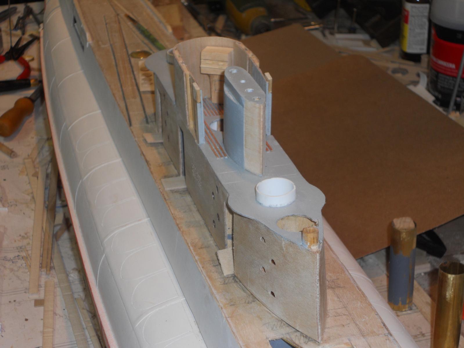
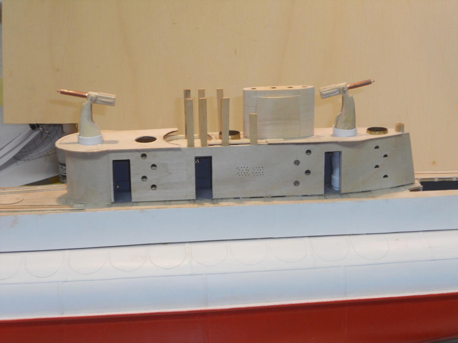
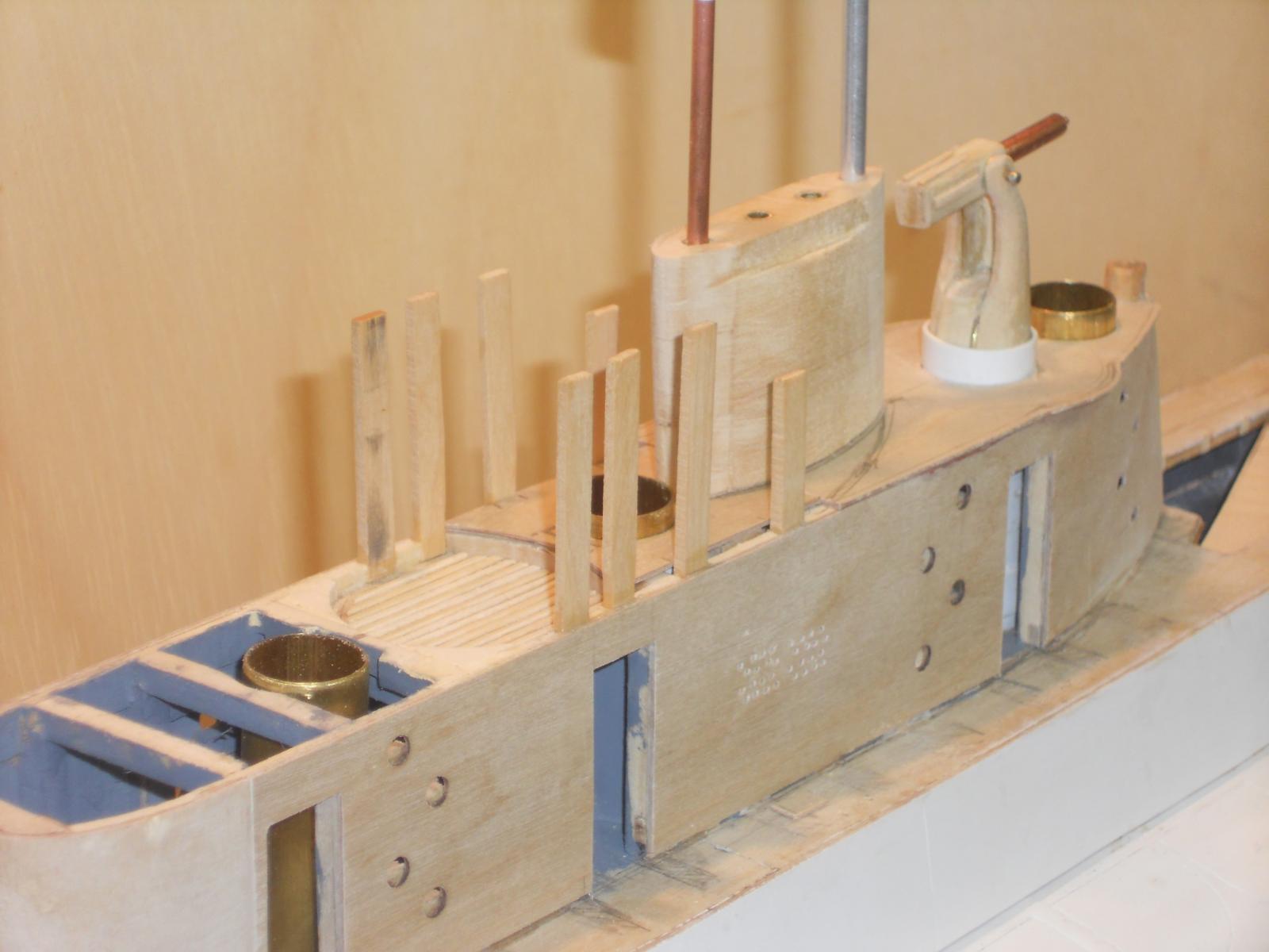
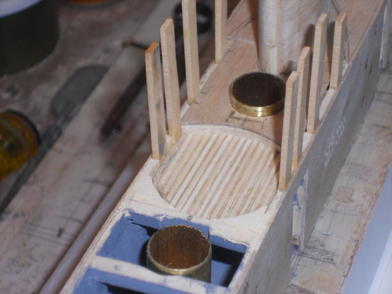
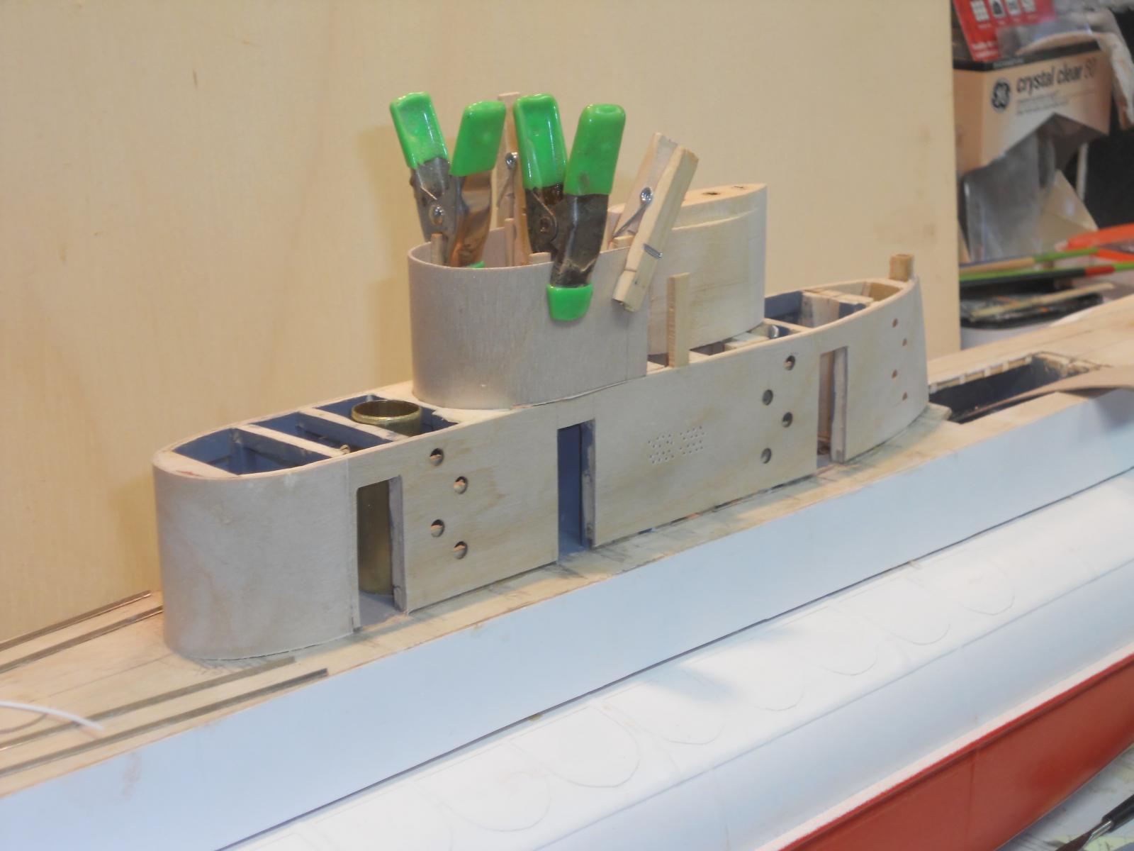
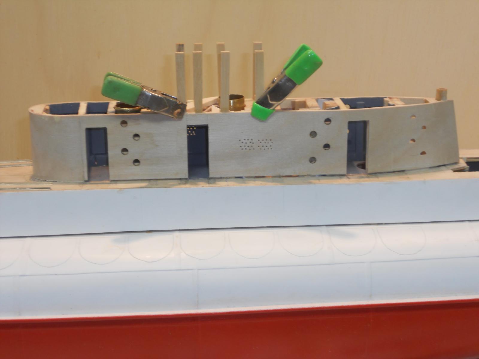
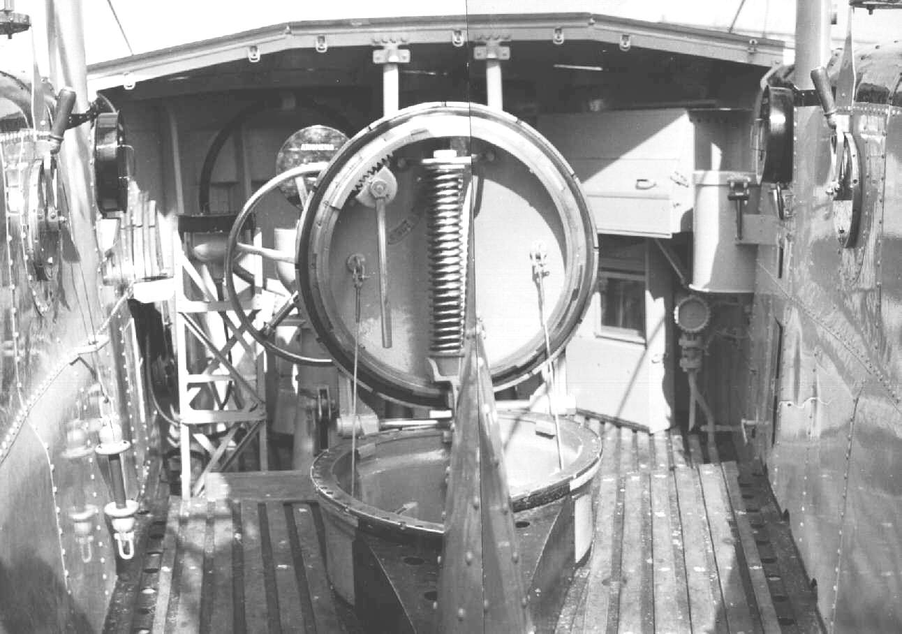
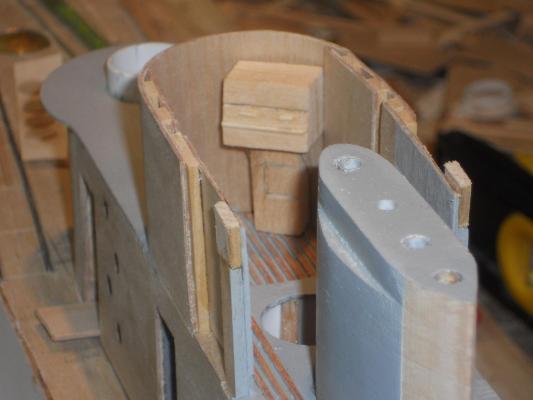
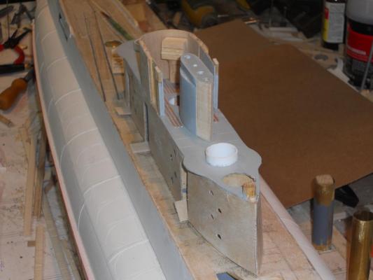
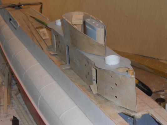
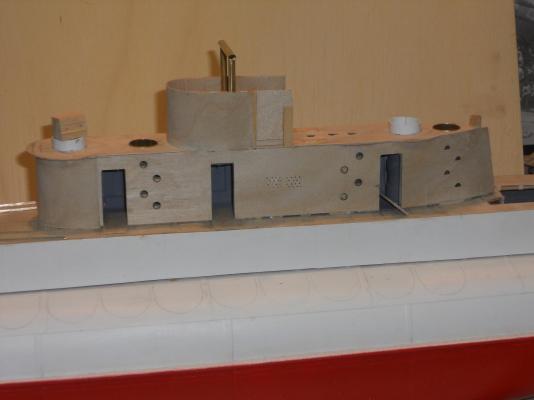
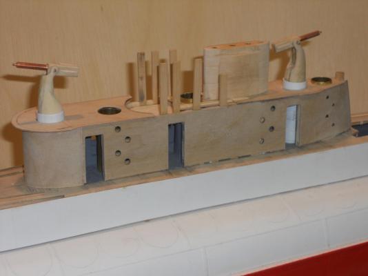
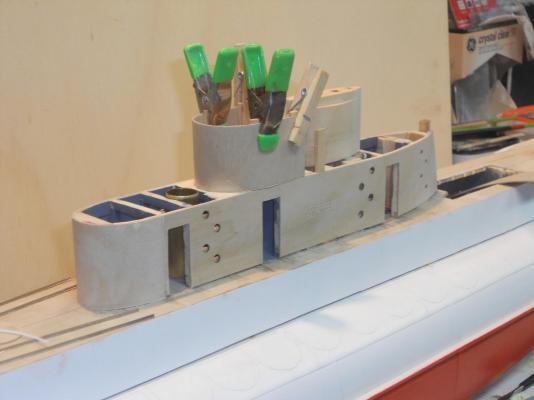
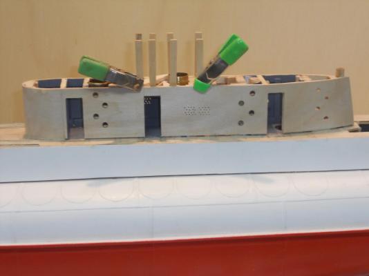
Hello all and thanks for visiting my shipyard and your "like" votes. I may not have posted a progress report for one day but that doesn't mean I have been idle I managed to glue the port side lower con side panel to the frames. I also painted the inside, at least those areas we can see through the door openings. Everything fits nice and smooth. Detail finishing will come after the doors are made and mounted. I had to remove the little steps at the aft end, even CA did not hold them securely. There's something with this plywood that doesn't like CA. Epoxy is a little netter but that's also iffy. I'll install them when I'm ready to paint, that way they won't be bumped. I have started with the bridge and the periscope housing. I'm using bass wood for the last one, it's a little easier to model. The cockpit of the brige will be a little tricky holding the 1 mm ply secure. I'm installing a few vertical frames but the only attachments for them are the upper longerongs of the lower con. I think that the front wether shield frame will add enough support. The cockpit is also lined on the inside that should also add some support. The concern I have is that weather shield. It looks like a compound curve with a half moon shape that extends as a top-railing like arrangement. See pic below. I think though that I'll make it a little simpler. Well, that's a worry when I come to it next week This shows the port side of the lower part of the conning tower. In my spare time I'll make the doors and the door frames and hinges. This is a composite picture of the bridge or "badkuip" (bathtub) as the Dutch submariners called it. As you can see there is plenty of "stuff" to add. Right now I don't know how much I'll make and install, enough though for the heck of it Cheers,

-
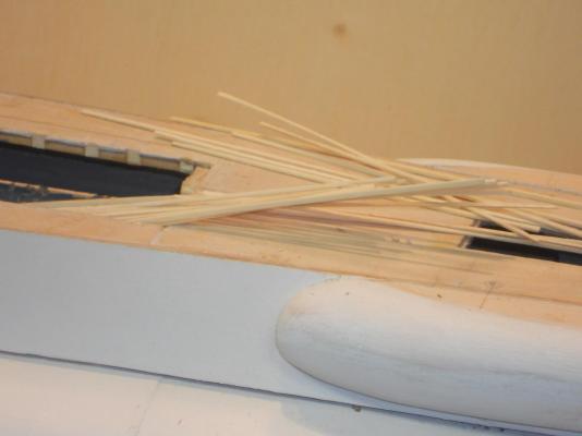
Ah yessss, the sticks are going in! Great progress, and that on a quiet day Cheers,
- 2,250 replies
-
- 1
-
-
- model shipways
- Charles W Morgan
- (and 1 more)
-
Not much was done today. I had a dentist appointment for him to install the two embutments in my two implants in the left upper jaw. All went well but it took quite some time, 2 hours. He had to cut the gums open again and I mentioned to him that he should have put a zipper in it Okay, the Novacane is worn off and I have absolutely no discomfort, which is a good thing. I managed to do some more work on the side panels though. I also cut the port side out and the door openings and made step holes in it. There is still some more detail work on them before I can glue them to the frames. Now, Boris mentioned to me in a personal e-mail that the Vickers Pom Poms on the Dutch subs did not have handles on them in the back. Oh dear, yes, he is right. I used the wrong installation as a guide and now I need to remove these nice handles and add some other stuff. I don't know if I have enough room inside the buns for that stuff but we'll see. Hey, that's what this forum is all about, helping each other - - - no matter that sometimes we have to take a step back before proceeding forward again. Cheers,