Louie da fly
-
Posts
7,973 -
Joined
-
Last visited
Content Type
Profiles
Forums
Gallery
Events
Everything posted by Louie da fly
-
 I've put this in my favourites as an example of difficult planking done well. Well? - - - Magnificently! Steven
- 525 replies
-
- 2
-

-
- anchor hoy
- hoy
- (and 1 more)
-
How big are those lubber holes, Dick? Are they big enough for someone to squeeze through? They look rather small - but doubtless you've already worked that all out. Steven
-
Hi Götz, Woodrat got here before me, but I was going to recommend you look at his build anyway. But I didn't know he was going to work on the top next! I haven't seen your top against your ship to compare sizes, but tops were very big at this time. I think ratlines would be appropriate for a Hanseatic ship - most northern vessels from this period seem to have had them. Steven
-
As usual, beautiful work, Dick. A pleasure to watch. Steven
-
Looking good. I like your planking! Steven
-
Yes, that's a very nice looking set of lines, Russ. A very attractive shape. (I wish I was as good at planking as you are). Steven
- 420 replies
-
- 2
-
-
- captain roy
- lugger
- (and 2 more)
-
Goetzi, I wouldn't want to impose standards or expectations on you. Ship modelling is fun, not some kind of competition. I added the links and pictures in the hope that you might find them useful, and because I love the ships of this period. I don't think enough people make models from this time (except of course the Santa Maria!) and I love to see someone embark on building one. And I've already learnt quite a bit from yours. Your work so far looks very good - crisp and precise. I look forward to following your build.
-
I agree, Christian, and I think the forecastle could perhaps be re-thought. The one on the Lisa seems a bit too "boxy" for the period. As far as the stern goes, I don't know if flat sterns were in use as early as 1500, but the Navicula Penitentie (printed in Augsburg) shows them by 1511. Both this ship and the Mary Rose of 1510 are basically carracks but with a caravel's stern. And the name Kraweel appears to come from caravel. Steven
-
Hi Götz, My German isn't good enough to read this site without help, but Google translate is pretty good - you can usually work out what it's supposed to say! Thanks for this information. I'd heard of the Hanse ports, but not of a kraweel. Yes, the Lomellina is contemporary and the Mary Rose is only a few decades different, but neither of them are Hanse ships, and it's pretty certain that there were major differences in building techniques and design between Hanse and other shipbuilders. I found these on the Net. They appear to be from about the right time frame The second is from Hamburg and the first has architecture reminiscent of Du"rer's pictures of German buildings (though they could equally be Dutch or Scandinavian). The ships in both have round sterns, unlike yours, but certainly by 1510 when the Mary Rose was laid down, flat sterns were in use. There vis also the flat-sterned ship on the front cover of Johann Geiler von Kayserberg’s Navicula Penitentie of 1511 here, and also you could do an image search on "ship of fools" for quite a few German examples of ships from the turn of the 16th century - some quite similar to your own, others with at least details that might be of use to you. 1494 1494? 1494 The picture by Ambrosius Holbein on the cover page of Thomas More's Utopia printed in 1516 has an interesting ship, though I don't believe the bows of ships of the time sloped backwards the way it's shown in the picture. Good luck with the build. If I can be of any help, please let me know. But we need photos of your build! Steven
-
I just had another look at the Lomellina report and it says the capstan was for raising the mainyard rather than the anchor, though I suppose there's no good reason it couldn't have been used for both. Steven
-
The Lomellina, a Genoese carrack which sank in 1516 had a capstan just aft of the foremast - see http://archeonavale.org/lomellina/an/l_102a.html its keel is 34.18 metres (112 feet) long with a 2.25 metre stempost (the sternpost is missing) - see http://archeonavale.org/lomellina/an/l_9a.html - compared with Mary Rose's 32 metres (I don't know if this was length of keel or overall length). The home page of the excavation is at http://archeonavale.org/lomellina/index.html The Red Bay wreck of 1565, though later (and a galleon, not a carrack), also had a capstan, between the main and mizzen masts (see http://www.patrimoniocultural.gov.pt/media/uploads/trabalhosdearqueologia/18/22.pdf ), though it's debatable whether this was for the anchor. The Complaynte of Scotland of 1548 refers to the anchor being raised by a capstan. I hope this is of help. Steven
-
This cunning plan is so cunning it's as cunning as a very cunning thing . . . . Steven
-
Impatience, mostly. After all the preamble and preparation, I really wanted to see what she'd look like. If I'd done it in tandem it would have taken twice as long to find out. As she was done on a plug there was no danger of an imbalance of forces from the planks on one side causing her to warp before the others were put on. Of course, I could have just taken the photos of one side and pretended I'd done both . . . Steven
-
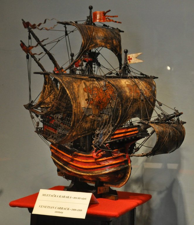
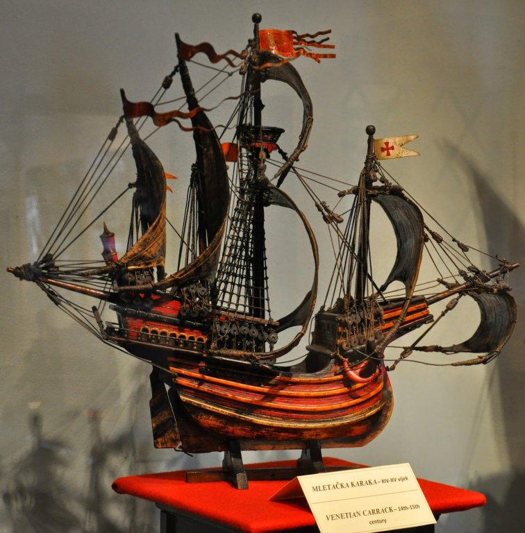
Very interesting Goetzi! This is a period and type of ship I'm very interested in. It is a little later than Woodrat's carrack or Nave Tonda, which you can also see in the scratch built forum. Though Venetian ships had many differences from those of the north, there were also great similarities. The main difference from carracks I can see from a brief glance is that yours is flat sterned, while those of carracks were round. The flat stern was just coming in about this time, and went on to be the dominant form for two centuries. I'd recommend you have a look through Woodrat's excellent build log - he's done a huge amount of research into ships of this period and you may pick up some valuable information. Some time ago I put up some links about vessels of this period at and and which I hope you you might find useful. Not only the shape of the ship itself, but very valuable images of artefacts etc. Looking forward to following your build! Steven
-
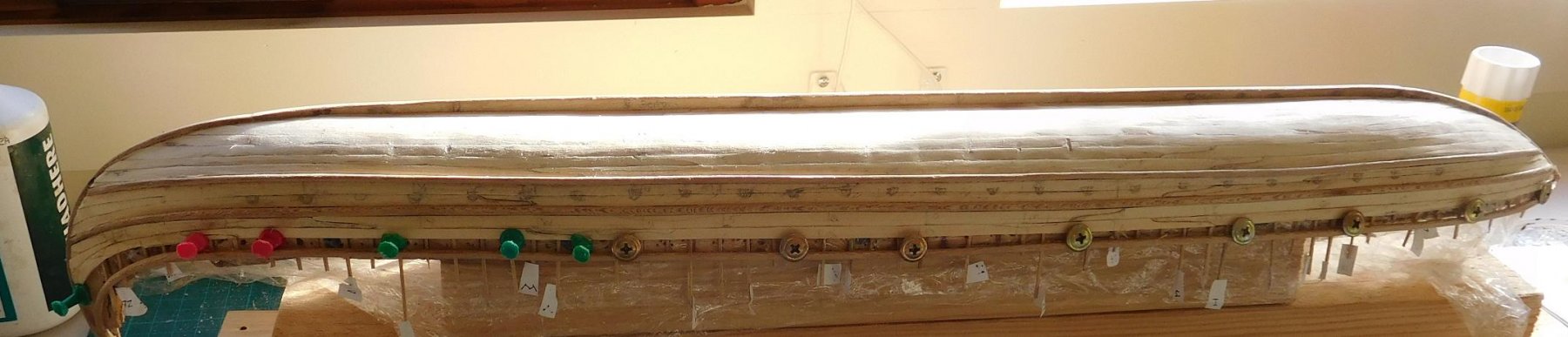
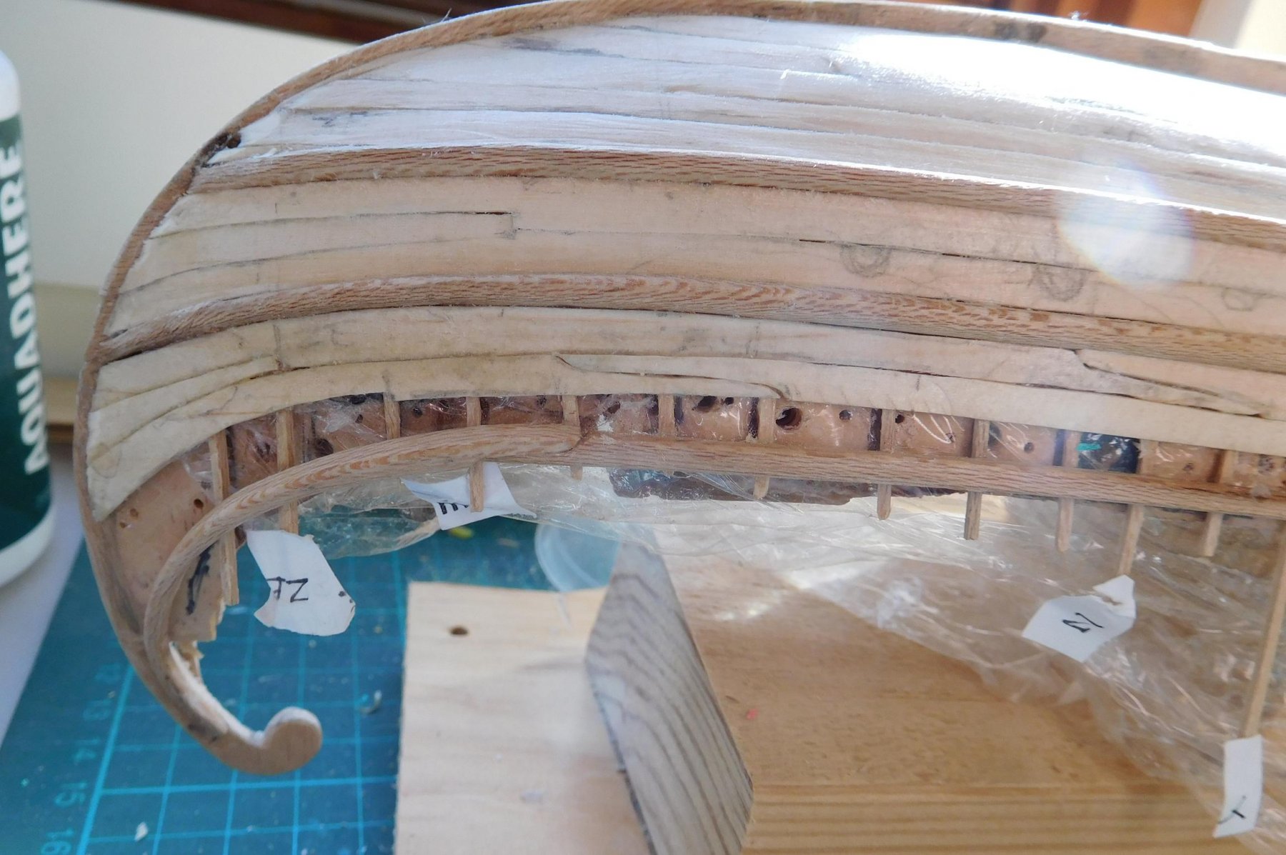
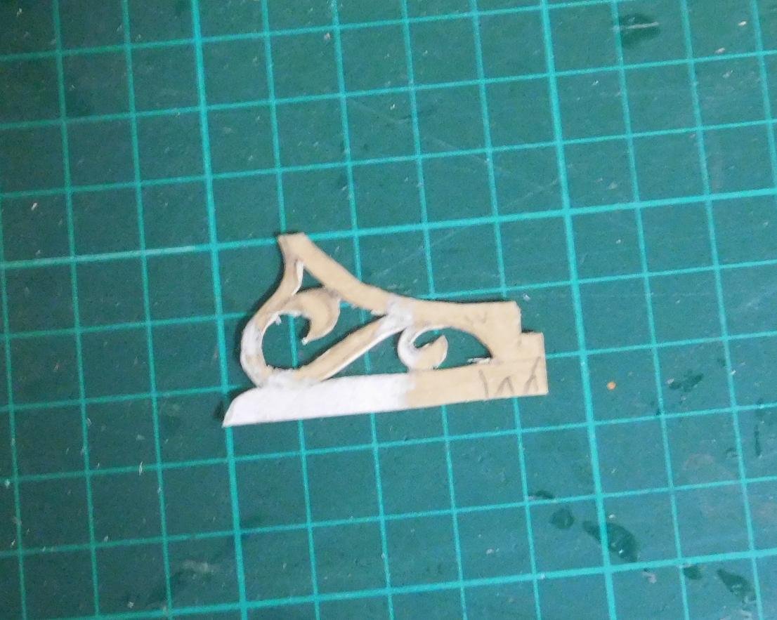
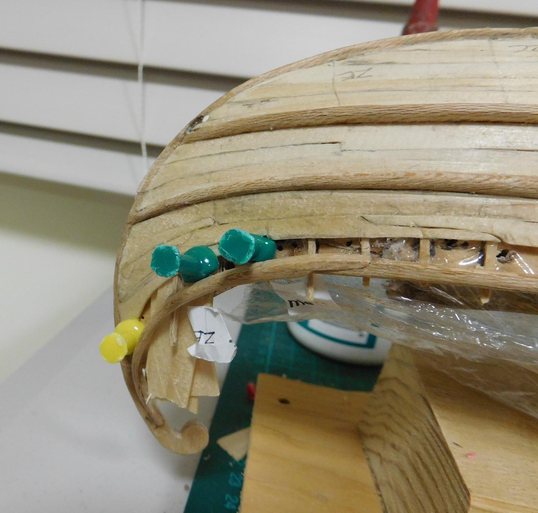
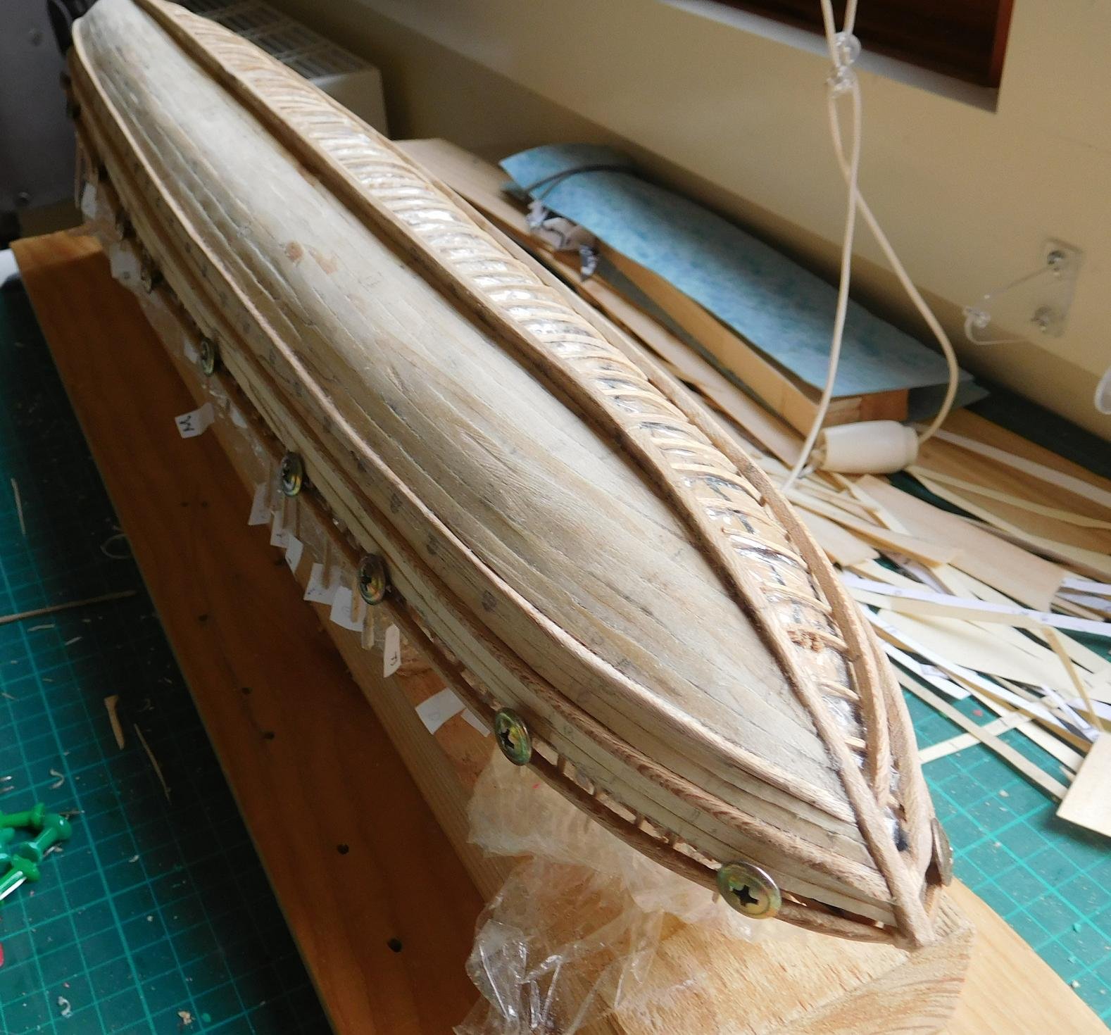
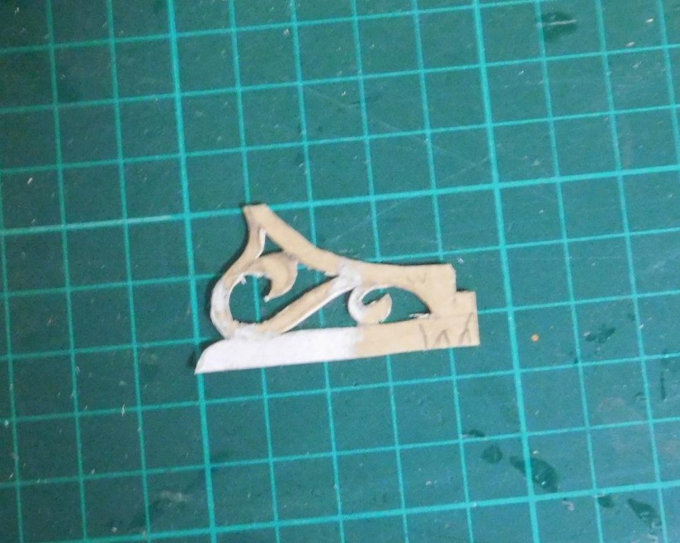
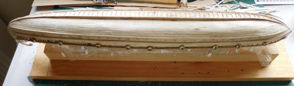
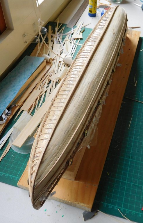
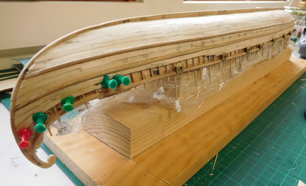
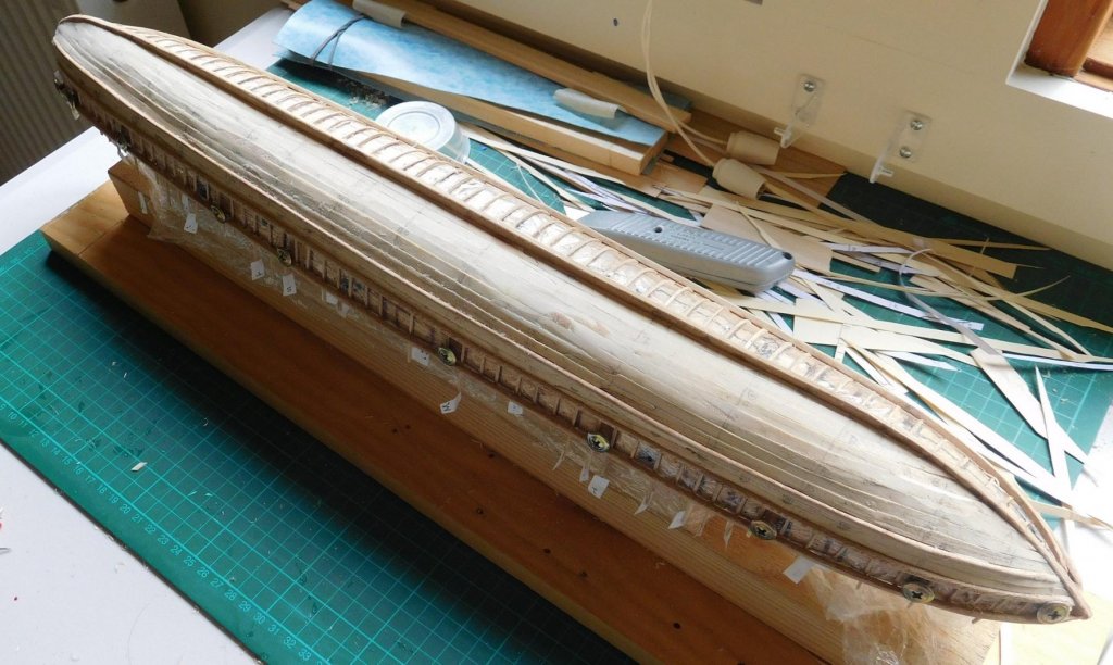
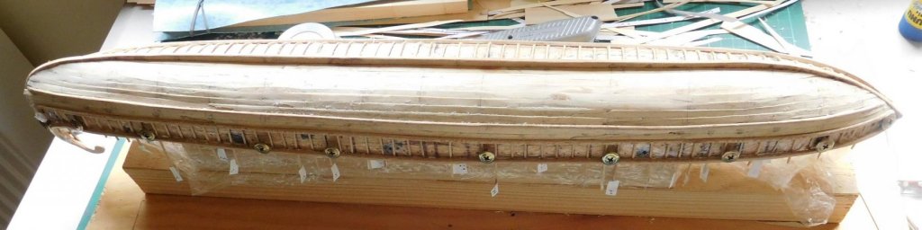
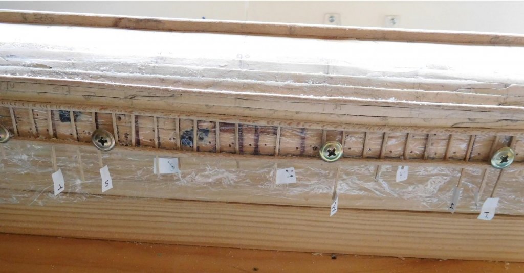
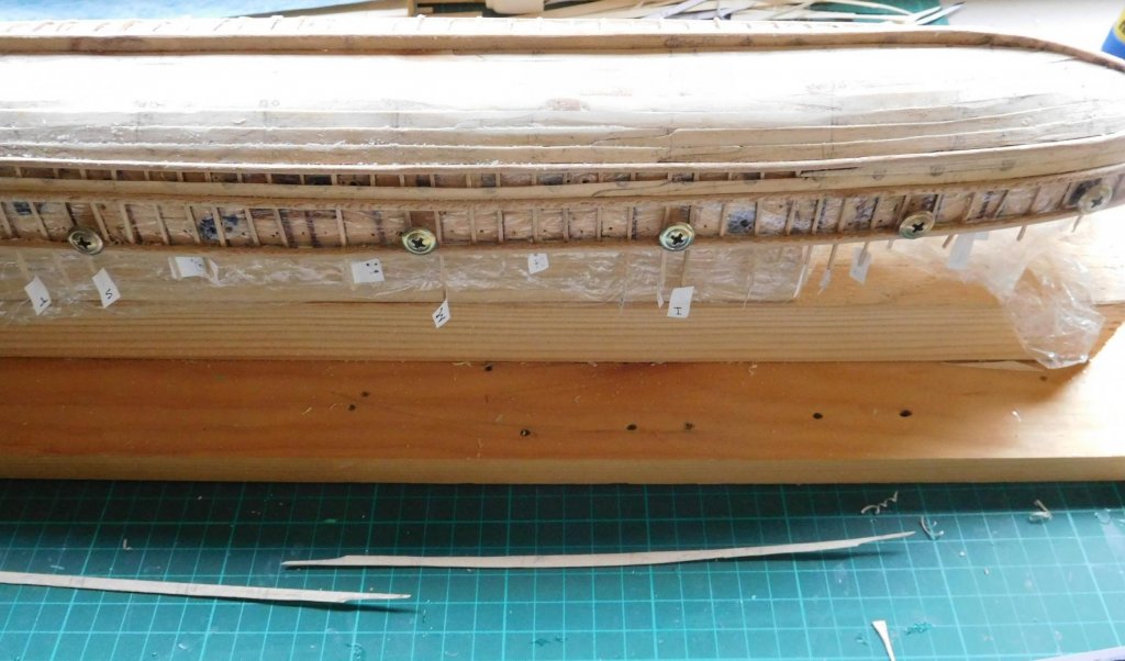
Thanks everybody for the likes. Much appreciated. Thanks for the compliments, Gerhard and Martin. I like the shape too. It's nice to be making such an elegant ship. Martin, you live in Gisborne! We're practically neighbours! Latest - I've now completed the second last plank on the port side. As mentioned before I had to miss the top one because of the screws in the way. I'll come back to it later. I've put in the drop planks now, and it's looking pretty good. A bit of filling needed, unfortunately, but not too much (it looks a lot worse in the photos than in real life). I've temporarily packed out the planking at the tail so it lines up as well as possible with the curved gunwale. I'm hoping I don't have to do too much adjustment at this spot. I might have to add another layer of planking to get a smooth line - I won't know till I put in the top plank. I've not yet used a third of the plank sheeting Woodrat sent me, which is a relief. I was wasting a few at the beginning and I was worried I'd run out before I finished. But it looks like it should be ok. I've started planking the starboard side. I felt I had to at least make a start on that, otherwise I'd be tempted to rest on my laurels. And I've worked up a design for the stand for the ship to rest on. This is half of it - it's mirrored at the right hand side (where you can see the slot for the keel). There will be two of these transverse to the hull, about 1/3 of the way in from each end, and sitting on a base running along the length of the ship. I'll be carving it in 3 dimensions in pear wood. The design itself is based on one found on an 11th century openwork Byzantine hanging lamp, so it's appropriate to the time and culture.


-
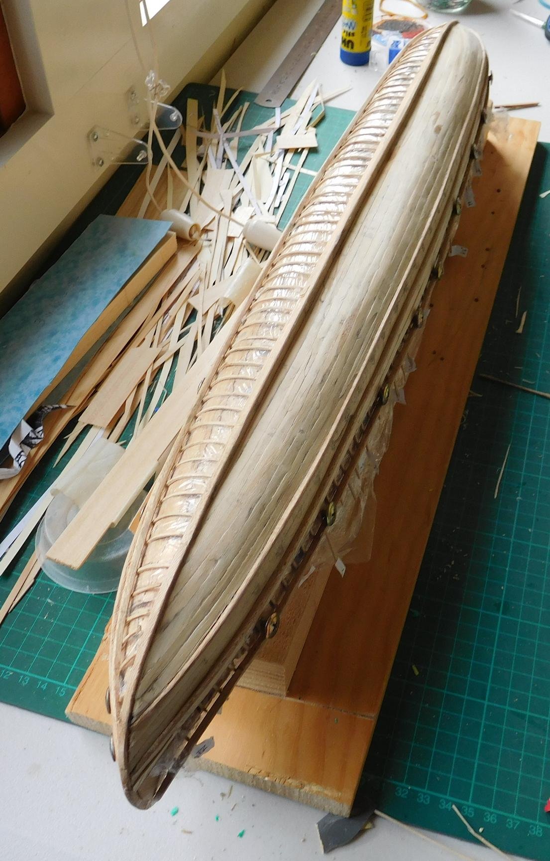
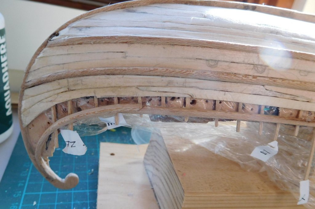
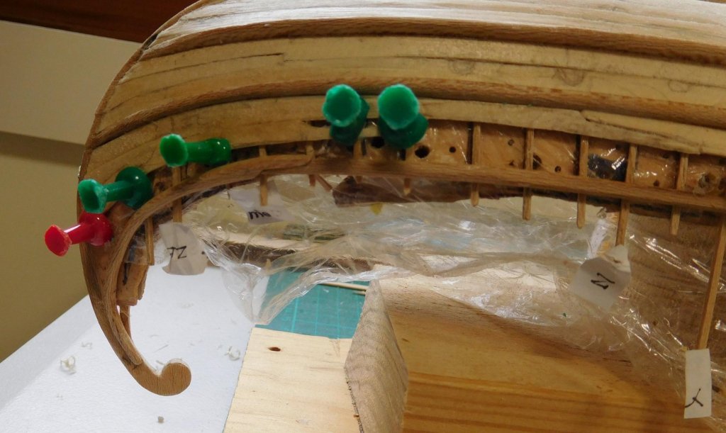
I'm onto the second last row of planks for the larboard side. I can't put in the top plank because the screws holding the ship to the plug are in the way. So once I've completed this run of planks I'll start planking the starboard side. I've learnt a fair bit while doing this and I hope the second side will be better. Planking the tail. Because of the extreme curve I've had to put in a couple of drop planks. I've sanded the planks down so they look more like the carvel construction they're supposed to be. Still got a way to go, and it looks like I may need to do some filling, and/or I might have to wait till I take the ship off the plug before I complete the smoothing off. Still, fairly happy with the way it's turning out. It's good to finally have something that actually looks like a ship! And I can't get over what an elegant shape she is. Steven

-
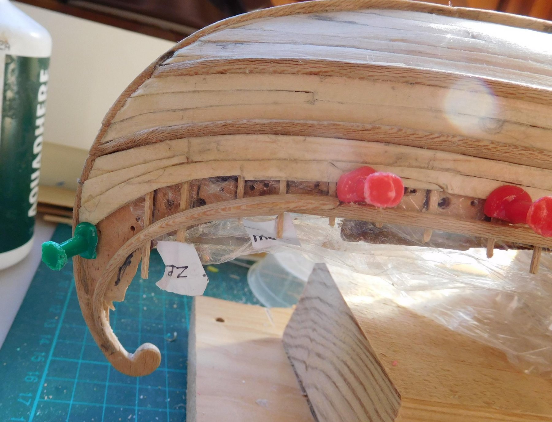
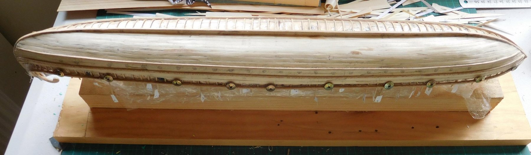
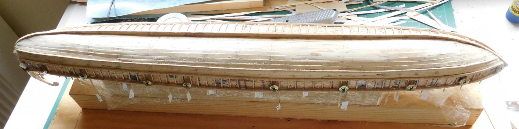
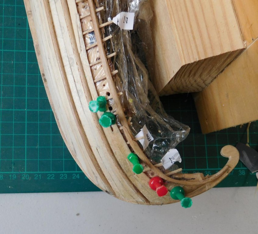
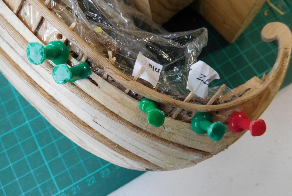
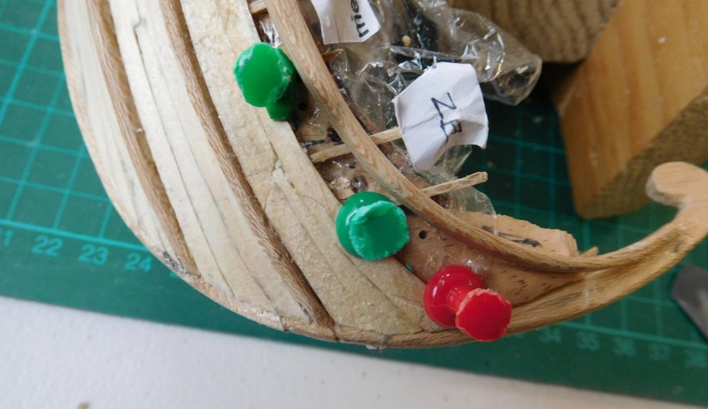
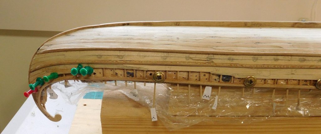
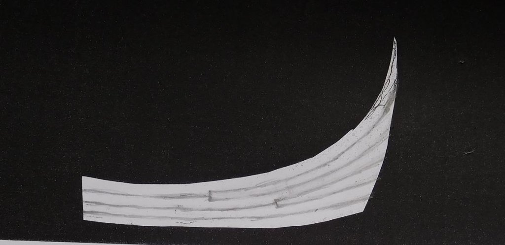
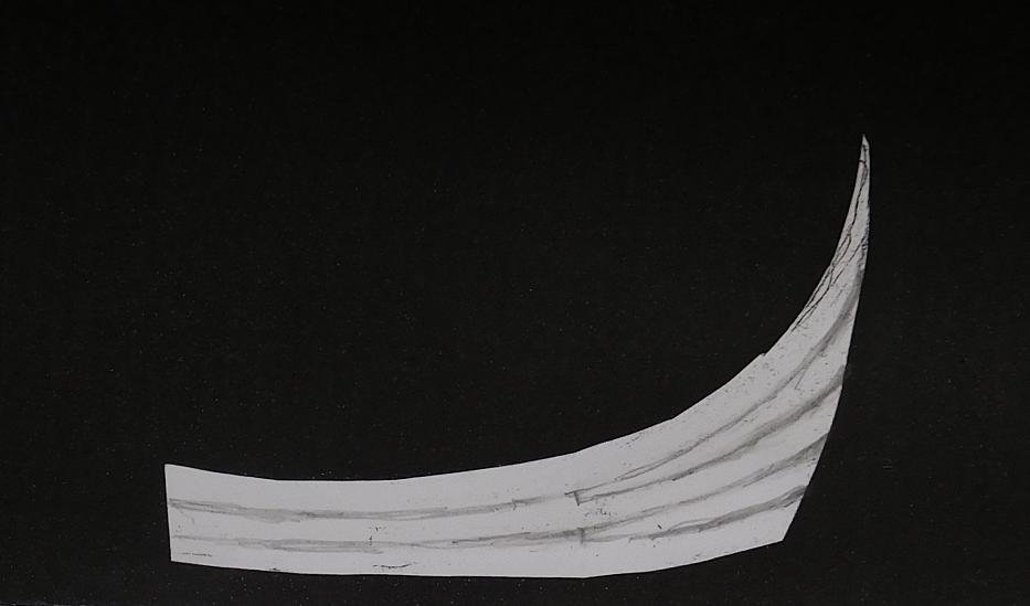
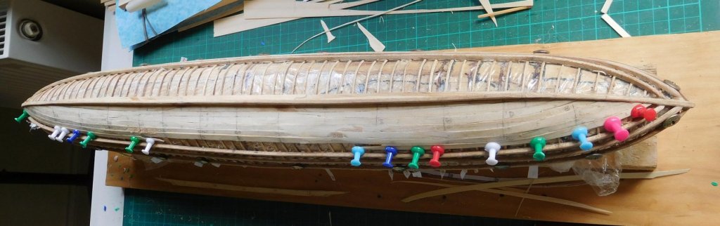
Thanks everybody for all the 'likes' More planking - at last she starts to take shape as a ship rather than just a framework! Not totally satisfied with my planking - I realise I still have a lot to learn about it, but the only way to do so is to practice practice practice - and I think for a first time it's not too bad. The gaps I've left between planks are pretty small and can be filled with wood dust and glue. But those scarph joints are a real trial! Closing up the gap between the first and second wale (counting from the keel). Two strakes between the wales - one in place, the other has the forwardmost plank glued in, and the other two planks shaped but not yet in place. As I mentioned before, I'll need to sand the hull smooth - it's supposed to be carvel built, not clinker! (the overlaps between planks are a result of my inexperience and my use of push pins to hold the planks in place). I'm learning as I go. You can see places where I've tried a little preliminary sanding and I think it will end up ok. And here she is with the gap closed up. Note the scarph joints. The dark pencilled-in semi-circles are where the oarports will be. I have to be very careful about placement; I've only got half the frames in place at the moment - the rest will follow after I've finished the planking - and the width of the oarport is the same as the gap between frames - there's only just enough room to fit the oarports in. I had hoped not to have to use stealers or drop planks, but with the shape of the rear 'tail" and the position of the wales I didn't have much choice and had to add drop planks. Note, the Viking longships didn't need them - they had planks following the curve of the ship's ends - but they didn't have wales to complicate the issue. It is known that dromons did have wales to strengthen them, and early during the design process I had to work out their position and shape, and now I'm living with the consequences. I've had to make the best of it, but I think it still doesn't look half bad. Two designs for the drop planks at the "tail", one with four main planks between the wales, one with three. As it turned out I'm not following either exactly - I'm doing a variation on the second one. Steven
-
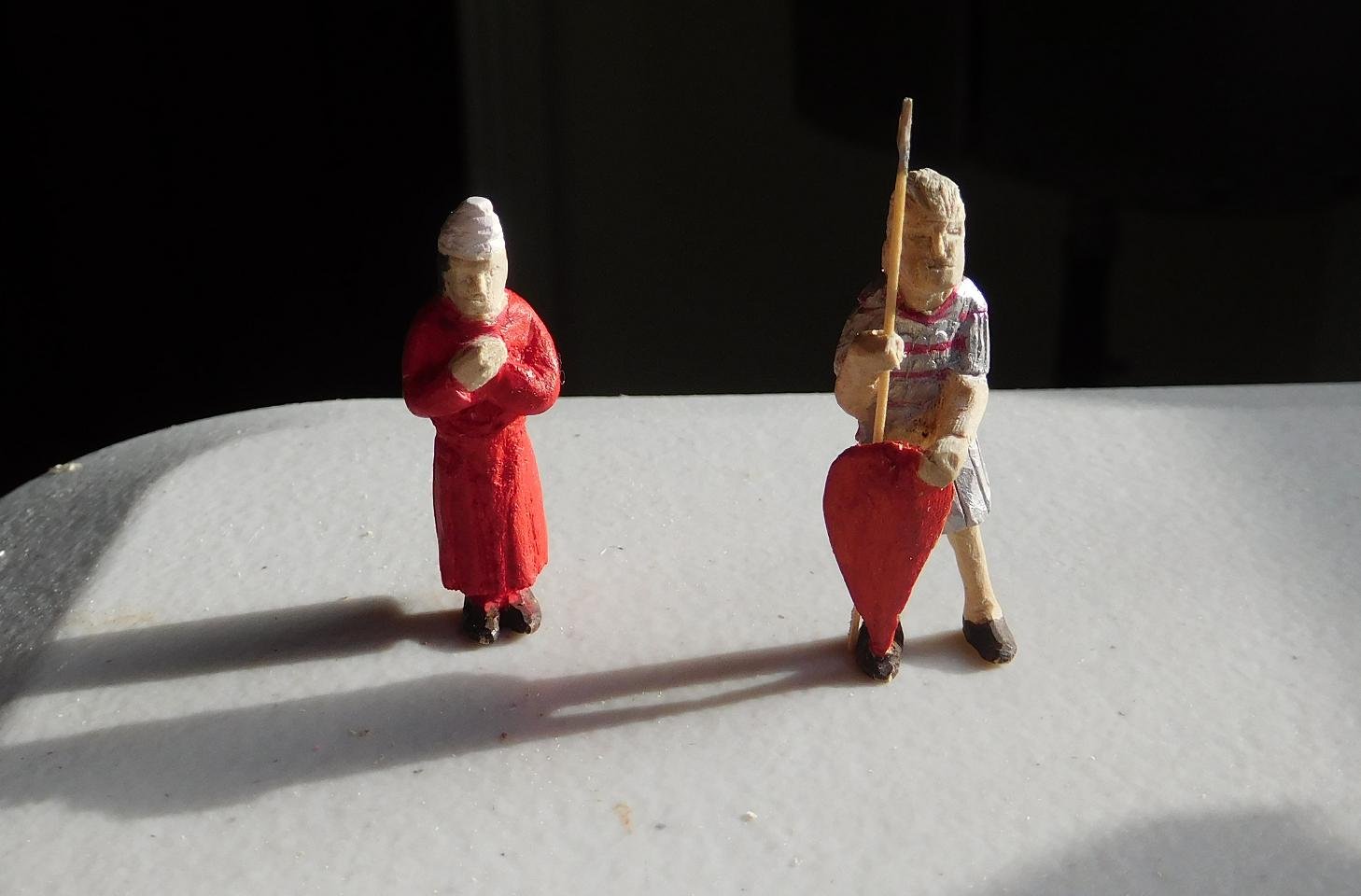
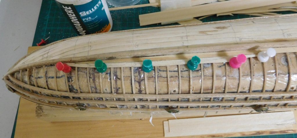
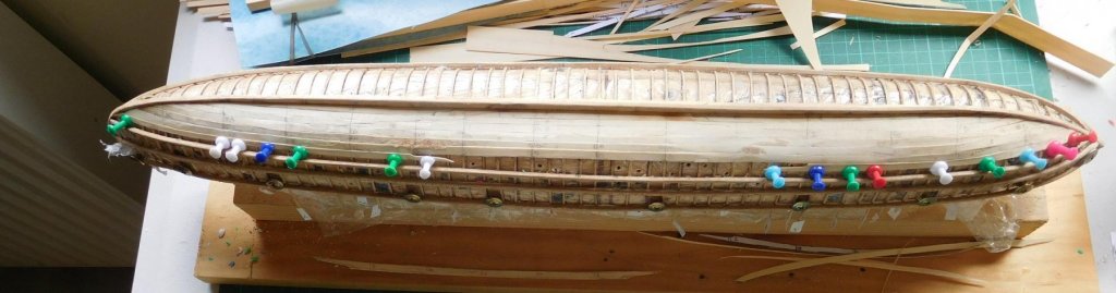
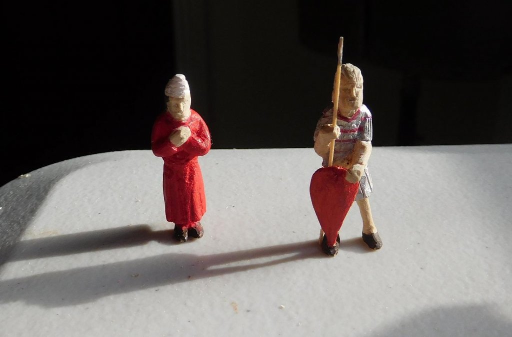
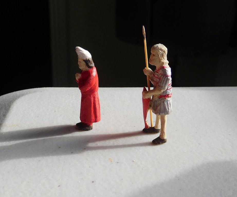
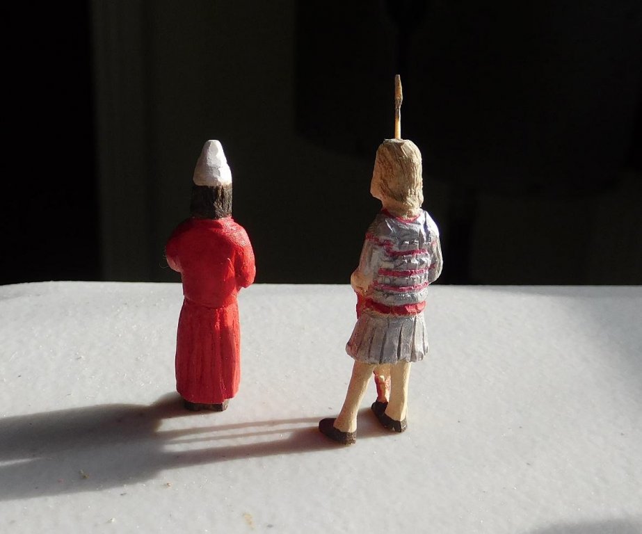
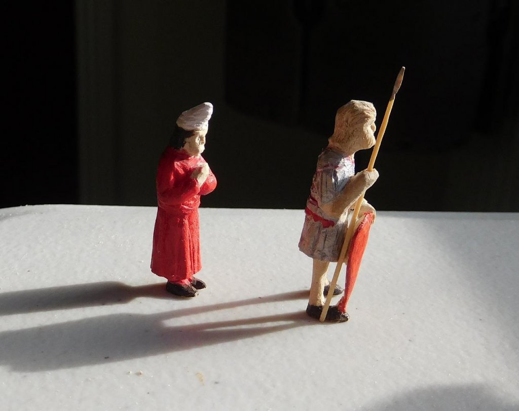
I'm more than 1/4 way through the planking now. It's not as tidy as I'd like - I've learnt a lot of lessons during the process about proper preparation of the substructure (i.e. getting all the frames at exactly the same level) which I didn't do this time. I first cut grooves in the plug for the frames, then I changed my mind and decided to get rid of the grooves and have the frames stand out proud of the plug - which is what I should have done in the first place. But because I couldn't cut the grooves precisely enough to the same depth with a handsaw they were all at slightly different depths and even after smoothing off the plug some of the frames still sit in the remnants of the grooves, while others sit fully proud of the plug. So I end up with wobbly planks. I've fixed that to a certain degree using filler made from white glue and wood dust. But I should have used dust from the (pine) planks instead of re-using the stuff from the (plane tree) frames and wales, because the colour of the filler doesn't match the planks. Not a big problem - I'm going to paint the bottom of the ship black to simulate pitch or tar, and the sides will be red and yellow, as befits the Imperial dromon. Five planks (plus garboards) in place: Another problem that has arisen is that the planks seem to tilt somewhat, so the edge of the new plank is a little higher than the edge of the previous one. I think this is because I've been using push pins to hold the planks in place as the glue dries. The pins push on only one side of the plank, so no matter how careful I am, it tilts a little. I can sand this smooth, but it offends me that I couldn't get it right first time. I'll have to find a better method of holding the planks in place. Putting the sixth in place: By the way, with the last plank so close to the wale, the flanges of the push pins were getting in the way, so I trimmed off one side of each flange and it fitted well. Dunno what I'm going to do with the last plank - nowhere for the pin to go - maybe I'll just have to hold the plank in place with my fingers till the glue dries . . . But if I ever make another dromon (fat chance!) I'll know what mistakes to avoid. All part of life's rich tapestry. I've also done preliminary painting on my two figures. Haven't sanded fully enough (a fact that isn't obvious until you take a detailed close-up photo) and I have yet to paint faces and the guardsman's hair, add shading etc etc , but it's starting to look good. Steven

-
(blush). Steven
-
Yes, the sail seems to be missing the characteristic "belly" of the carrack's sails in its current incarnation. I don't know if the joins with the bonnets aren't a little too stiff and contributing to the problem. Or perhaps the cloths - or perhaps both. Maybe the cloths could be suggested (another modeller uses thin white paint lines to represent the joins) rather than stuck together "for real". After all, in scale, the seams would be vanishingly thin. Perhaps carving a mould out of wood, or better still (easier to carve!) styrene foam would do the trick? If you make a convex shaped mould and drape silkspan (or perhaps handkerchief material or cotton from an old sheet) over it with thinned glue? You'd probably have to press the fabric into the creases in the mould where the seams are, but it might be worth trying. Steven
-
Very interesting, Dick. I just searched them up on the net and they cost about 30 bucks. Pretty good value. And the built-in LED light would be a bonus as well. I like a LOT of light when I'm ship modelling. Steven
-
Hi Vivian, You certainly don't need to follow Corel's white painted lines. They don't appear in contemporary paintings of coccas - look particularly at Carpaccio's St Ursula series of paintings for extremely good representations of these vessels. I think I've read that paper of Valenti - very impressive. And if you want to get rid of a mast and make other changes to make it closer to a late 15th century ship, you could end up with a very good model indeed. You're making good progress with the build, but may I put in a suggestion? I really have trouble with the shape of the bow on the corel model - I don't believe the bow should be inclined backwards as it is. I know it's on the votive model, but I think the modelmaker got it wrong - and Corel have inclined the bow even further. Look at contemporary pictures and I think you'll find a more believable bow shape. The trouble is it might be too difficult to change the model's central "spine" to a better shape at the bow - and you'd probably have to make the foremost bulkhead narrower as well, but you've already glued it in place. I was going to mention this before but wasn't sure if I should, as it might sound too much like criticism. And you've gone ahead so fast I don't know if it could be changed now. But if you're prepared to do it, I think it would make a more accurate representation of a ship of the time. Steven
-
Hi Vivian, This is a great era to be working with - not enough people make models from this time period. As far as I can see, the 15th-16th century Mediterranean cocca is the same ship as the nave tonda (round ship) and further west would be called a carrack (same ship, different names). I see you're already aware of Woodrat's brilliantly researched Venetian nave tonda, and I'd highly recommend you study his build log carefully if you want to get your 15th century details right. I certainly found several of my own assumptions about carracks had to change in the light of Woodrat's research - for example the shape of the bow - the carrack had much finer lines and a sharper bow than I'd thought. It's evident your model is based on the contemporary one below. I haven't seen this one before, and it's very interesting. It's oversimplified and some of the details are incorrect; I expect it's a votive model - these were often donated to a church by a mariner in gratitude for a safe voyage. But it is very evidently a 16th century ship - the four masts and the rig make this certain. Changing it to a 15th century ship might involve a lot of work - perhaps more than it's worth. The Mataró ship is genuinely 15th century, and maybe you should just build this kit as it is rather than try to change it, and then once it's complete start on the Mataró ship . Steven
- 61 replies
-
- 10
-
-

-
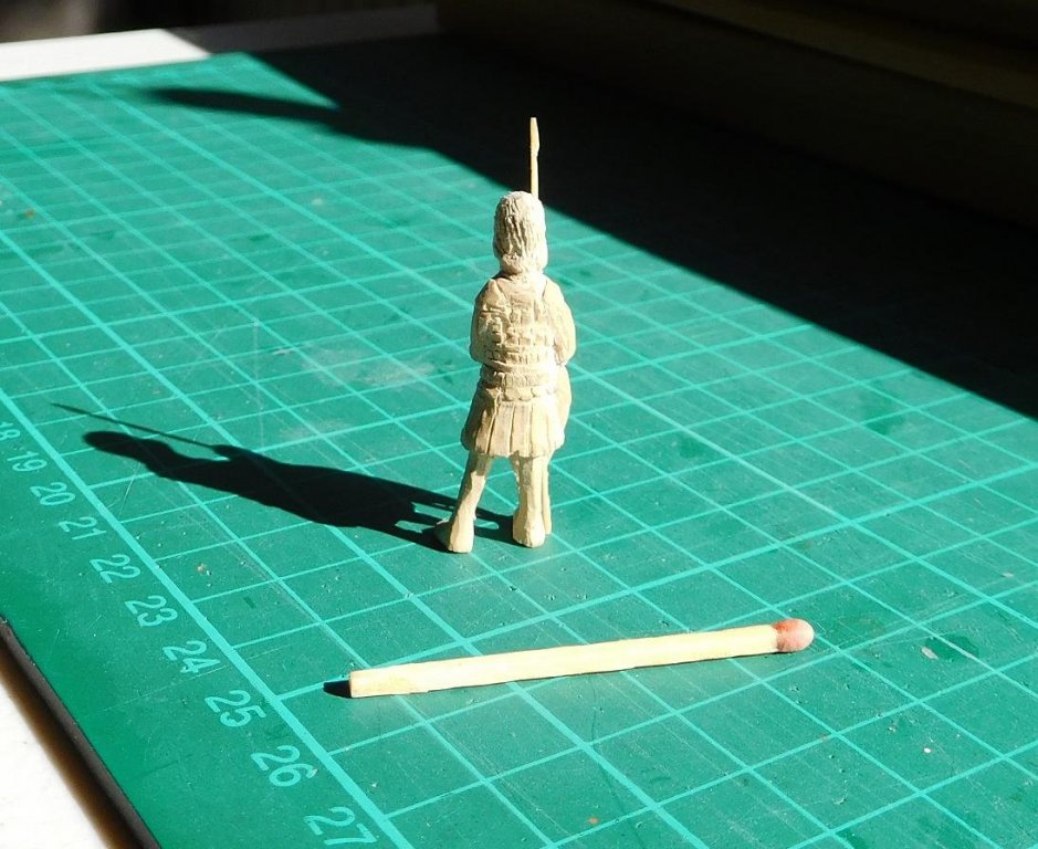
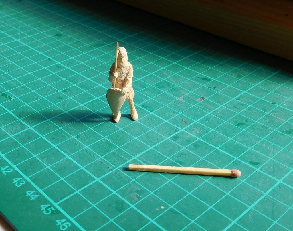
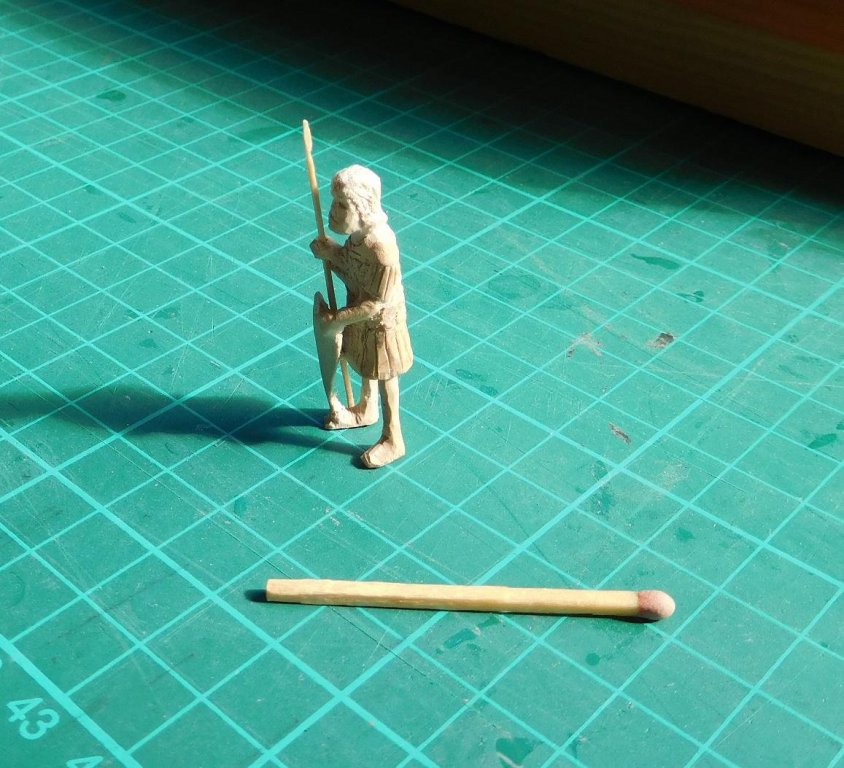
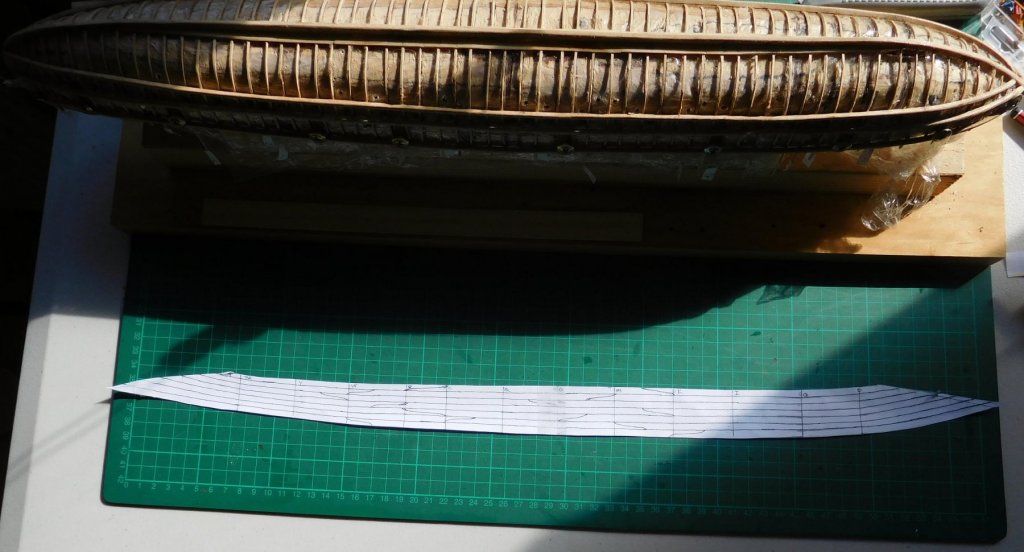
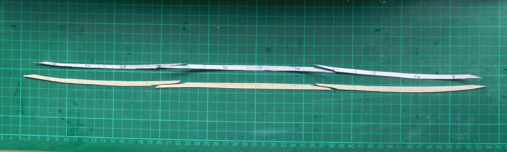
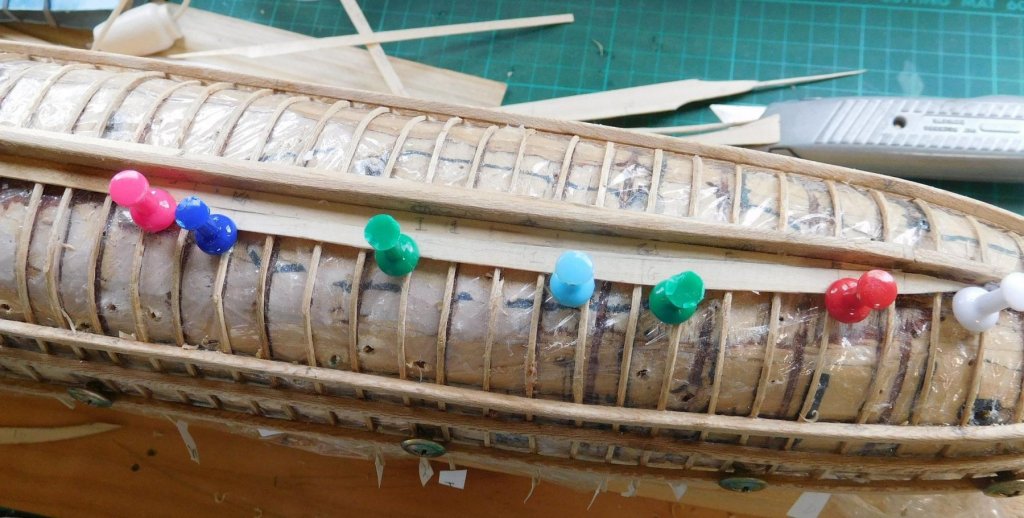
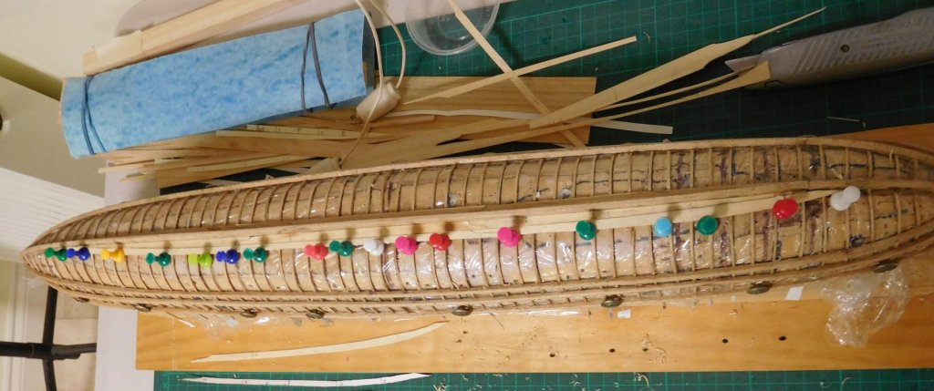
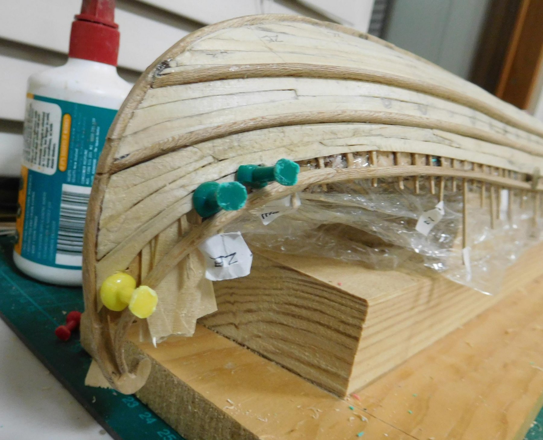
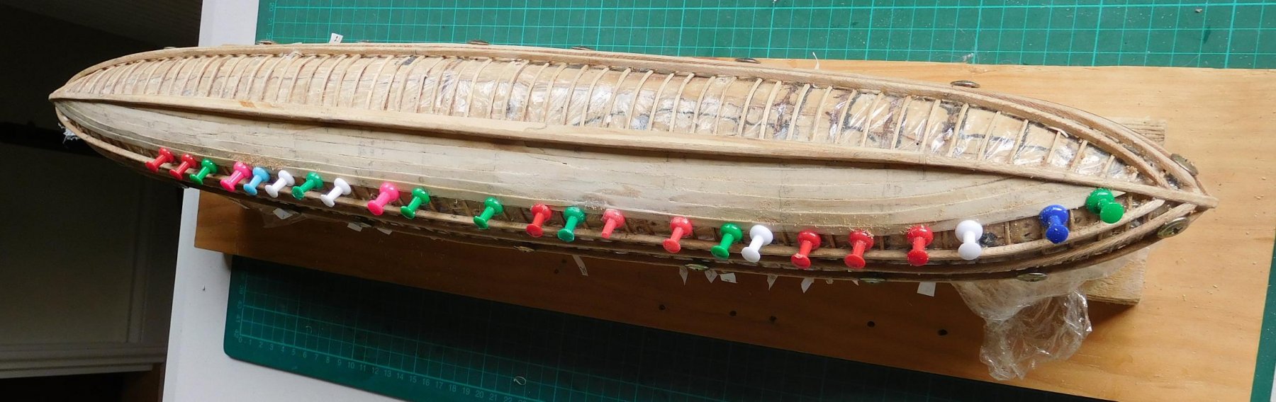
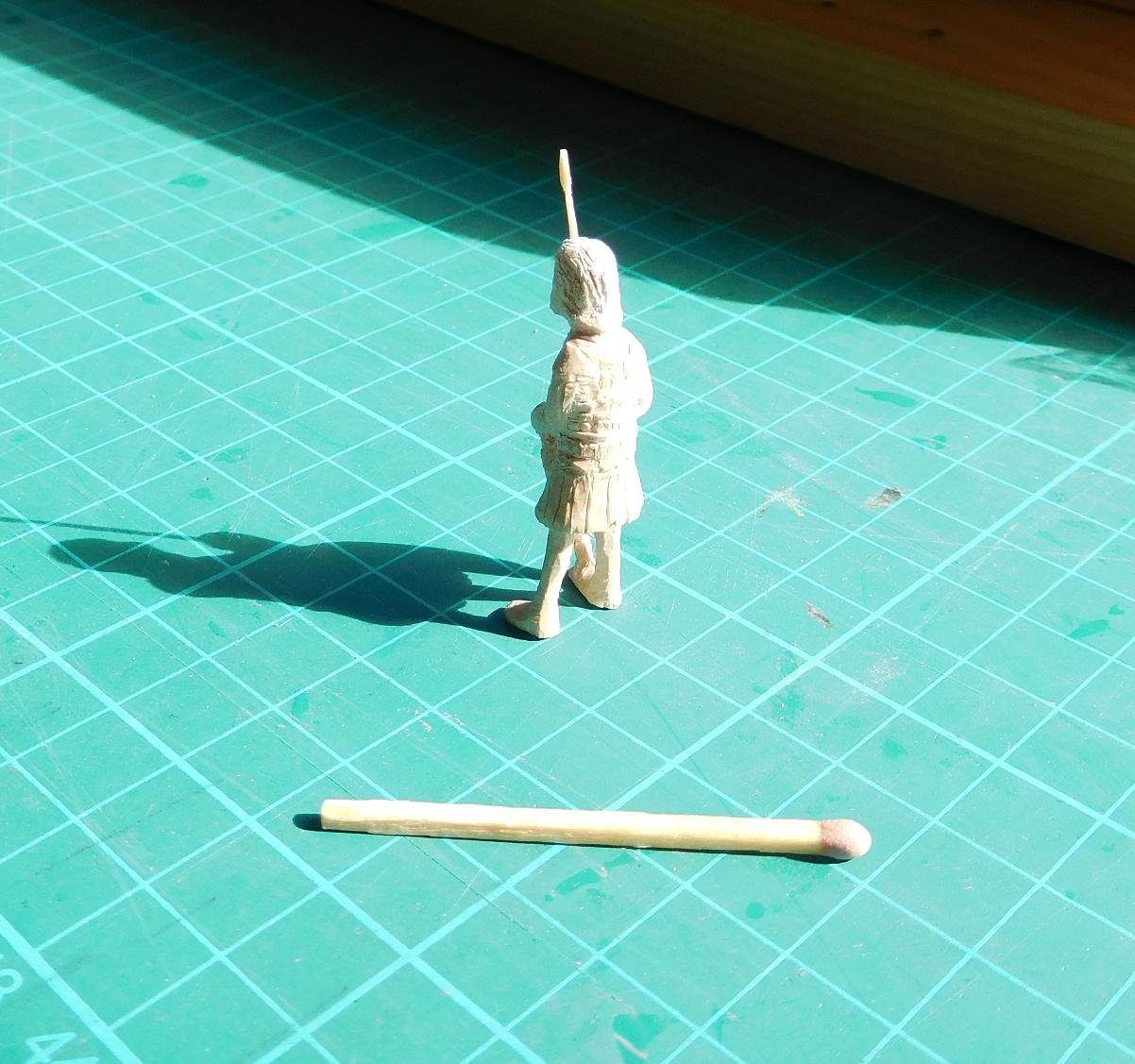
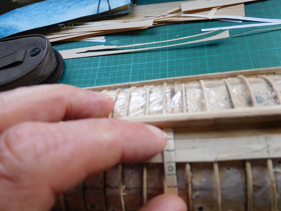
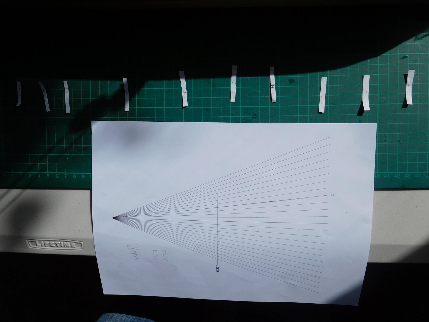
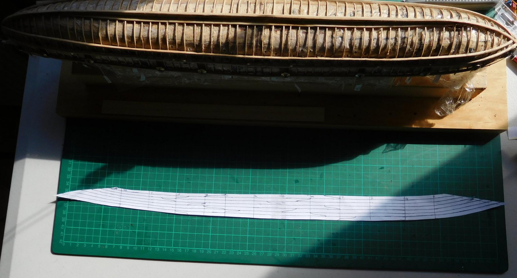
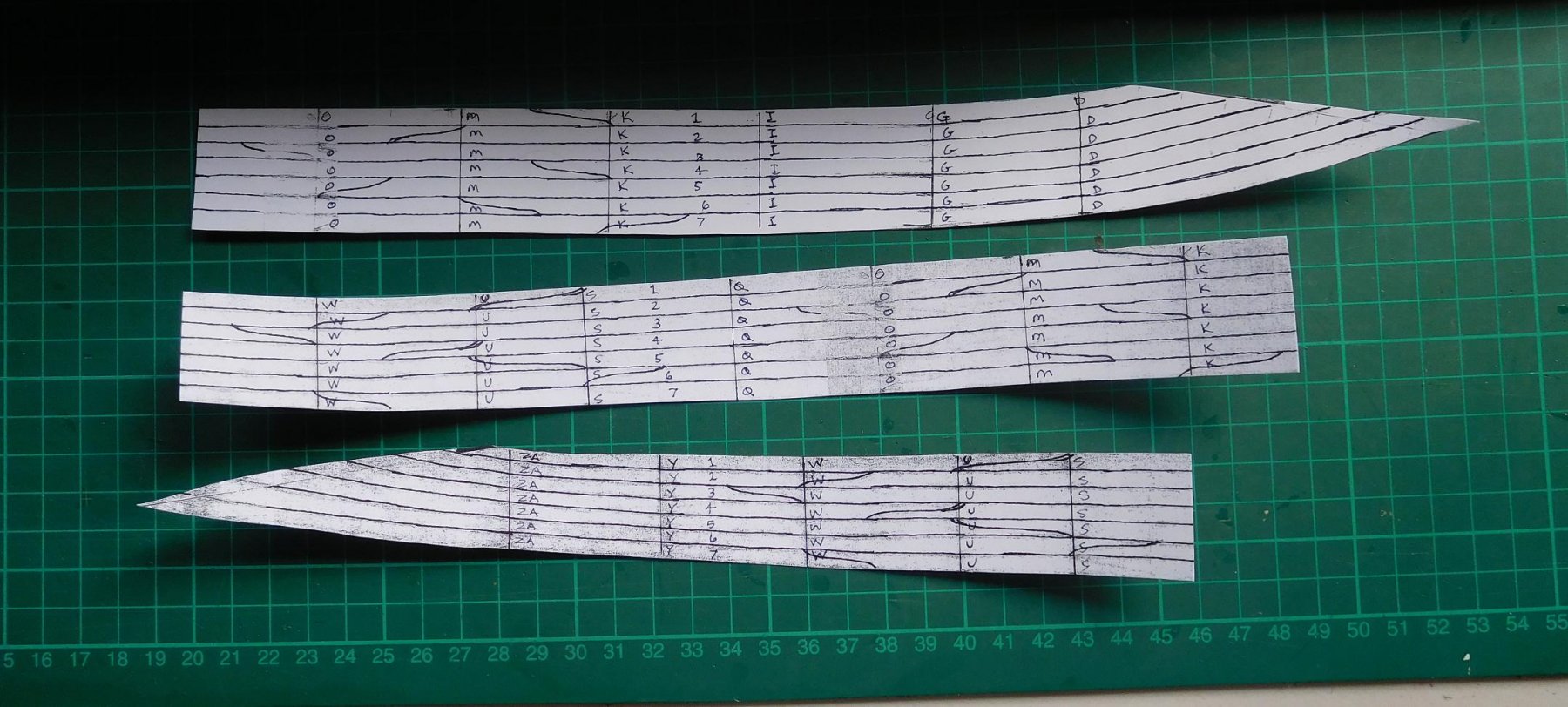
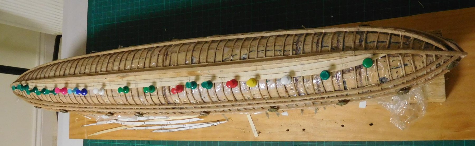
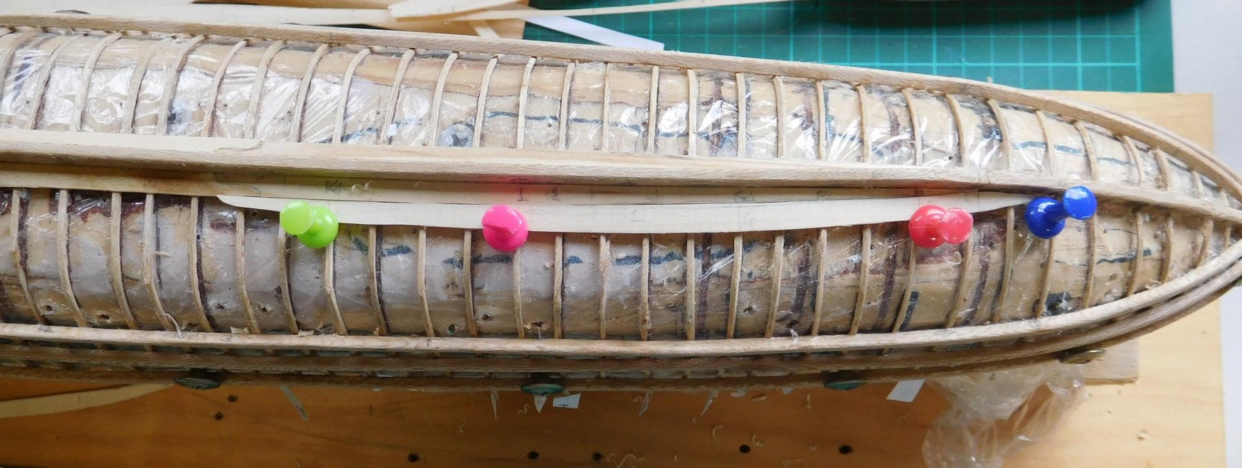
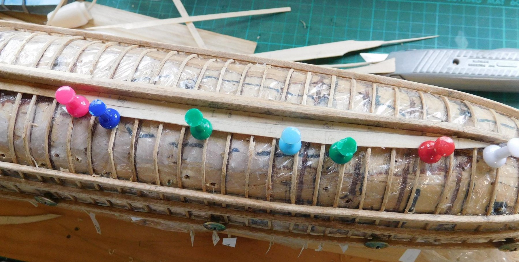
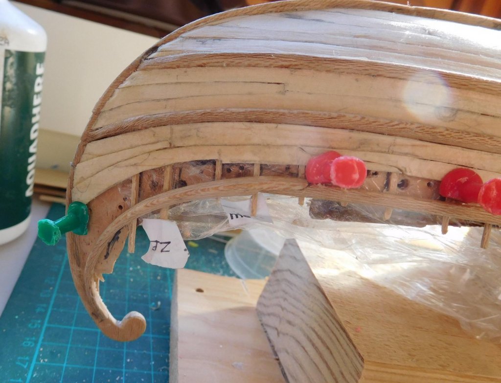
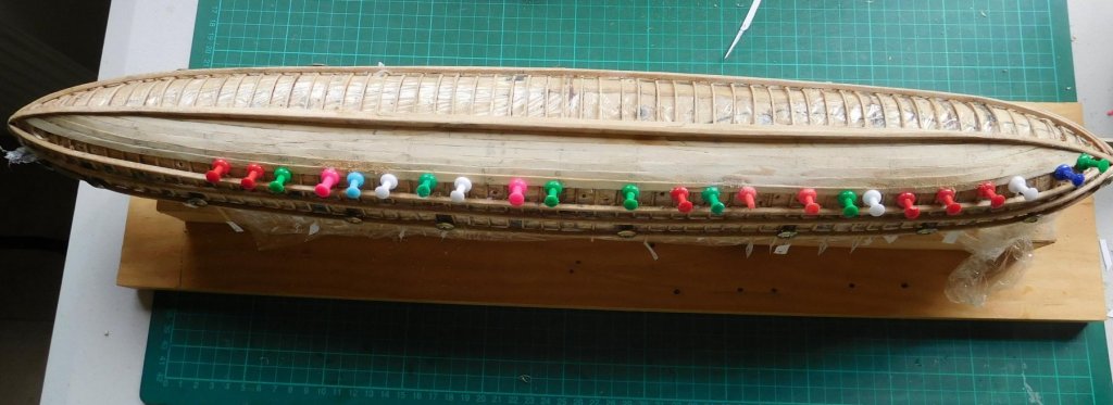
I’ve finally started the planking on my dromon. It’s been a long time coming. I’m very grateful to Woodrat who heard I had no proper bench saw of my own so he cut sheets of pine half a millimetre thick and sent them right across Australia for me to make my planks from (the guy across the road had cut some for me, but though I appreciate the gesture they were 50% thicker at one end than the other and really weren’t usable). I did a lot of reading on planking techniques, because I really wasn’t confident I knew what I was doing. I decided to use the planking guide I found on the MSW site but I had trouble working out how to go, and after a lot of thought I worked up a template that suited my style of working. It may not suit everybody or every ship, but it seems to work for me. Following the method I got from MSW, I made up strips of paper to determine the width of each plank where it crossed a frame, dividing the distance between the keel and the first wale by the number of strakes (in this case 8, including the garboard strake). But then I went off on my own – I made up a template that covered the whole area between the keel and the wale from end to end of the ship and using the strips I marked the strake widths where they crossed the frames, and then joined the marks to draw the strakes on the template (along with placing the scarph joints). There are three planks in each run, and they are joined end to end with a long S-shaped scarph joint based on those of the Byzantine galeae found in the silted up Harbour of Theodosius in Istanbul (the Yenikapi ships). This kind of joint is needed because the frames are so thin it would be impossible to butt-join planks at a frame. So the joint is spread over several frames, with fixings at each frame. Surprisingly, on the Yenikapi ships these joints aren’t spaced as far apart on adjacent planks as we’d normally expect. But that is probably compensated for by the strength of the scarph. Then I photocopied the template and glued it onto card. I cut it into three sections – to make the three planks in each run. After that I could cut out individual plank templates from the card and transfer them to the wood of the strakes. Then it was a matter of trimming the edge of the strake so it fitted exactly against the keel (for the garboard strake) or the edge of the next strake. Very fiddly. After that I used my strips of paper to check that I had the width of the strake right. It was always too wide – maybe the pencil wasn’t sharp enough - so then I marked the right width at each frame and drew a freehand curve to join the marks and trimmed the strake to width. Checking the strake width with the guide. I used push pins to hold the planks in place. This meant I had to drill a whole lot of 1mm diameter holes in the plug (with a hand-held drill, so always running the risk of breaking the drill) to hold the pins. I put glue on each frame (just the width of the strake) and glued along the inner edge of the strake and along the scarph joint. I started with the garboard strake – not the starboard garboard; it was the larboard garboard. So far I have both garboard strakes and three planks on one side . It’s very fiddly and demanding work and takes much more time and effort than I’d expected. But it’s very rewarding. Here's the first plank dry fitted. And glued down. Here's the garboard and the first run of planks (the pale blue rectangle is the packet of pine sheets Woodrat sent me). And the second run of planks fitted and glued in place. I’ve also been working on the Imperial guardsman to accompany the Emperor on board the ship. I’ve done the detail work on his armour and his hair. He just needs a bit of sanding and painting and he’s complete. Matchstick included for scale. I made him taller than everybody else – he’s going to be one of the Emperor’s Varangian (Russian Viking) guards. The Vikings of Russia were described by the Arab traveller and chronicler Ibn Fadlan as “Blonde-haired, ruddy and taller than date palms”. I think my carving’s getting better. Unfortunately, this makes me a little dissatisfied with my earlier efforts and want to re-do them. But that way lies madness . . . The detail of these figures is sufficient for the scale they’re in, and anyway they’re just accessories for atmosphere - they’re not supposed to distract the attention from the ship itself. Currently I’m at the limit of the detail I can put in just wearing my normal glasses. If I wanted to improve it I’d have to invest in a super-duper magnifying glass, which I’m not prepared to do. Steven