Supplies of the Ship Modeler's Handbook are running out. Get your copy NOW before they are gone! Click on photo to order.
×


mikegerber
-
Posts
213 -
Joined
-
Last visited
Content Type
Profiles
Forums
Gallery
Events
Everything posted by mikegerber
-
 Good morning everyone Thanks to all who are following along, commenting, for the appreciation and for pressing the like-button! @Patrick Regarding the approach: Yes, I like to cope these things first mentally, the implementation then it's much easier for me. @Matija Oh thanks! I just hope that I can learn as fast as the build grows - but I know, these are my own expectations ... @Michael Yes, you're absolutely right. It's really phenomenal, how fast and faultless the eye perceives differences from a series - the eye is a merciless judge! Regards Mike
 -
Pen Duick 1898 by Mfelinger - 1:20
mikegerber replied to Mfelinger's topic in - Build logs for subjects built 1851 - 1900
Hello Matija Great workmanship! - I just learned a few things. Thank you for posting this skills. Regards Mike -
Hello Kevin I discovered just your log and I will surely following ... ... like your project Regards Mike
-
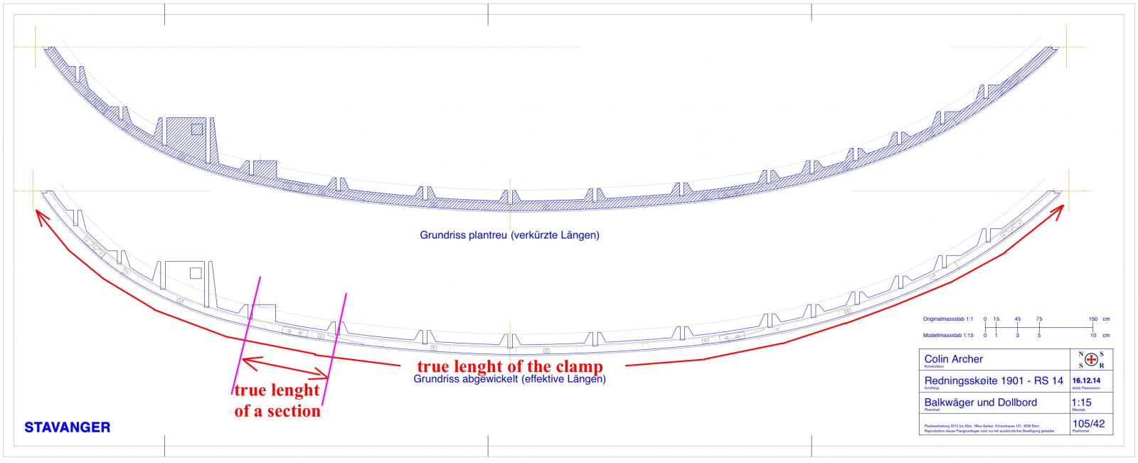
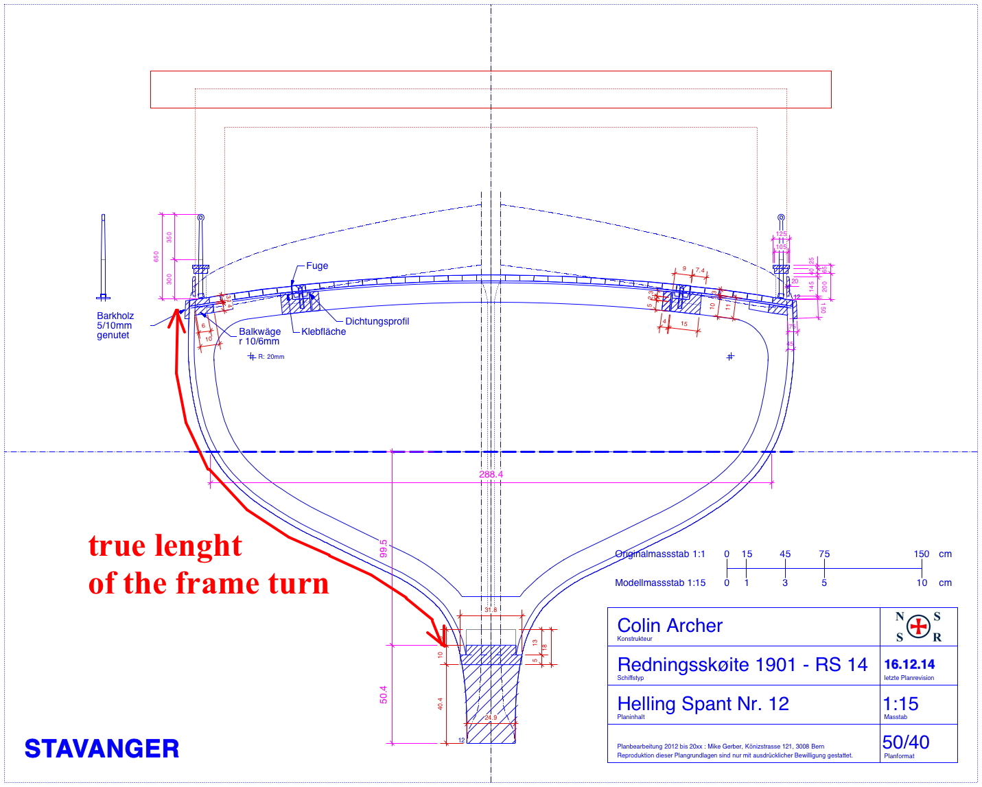
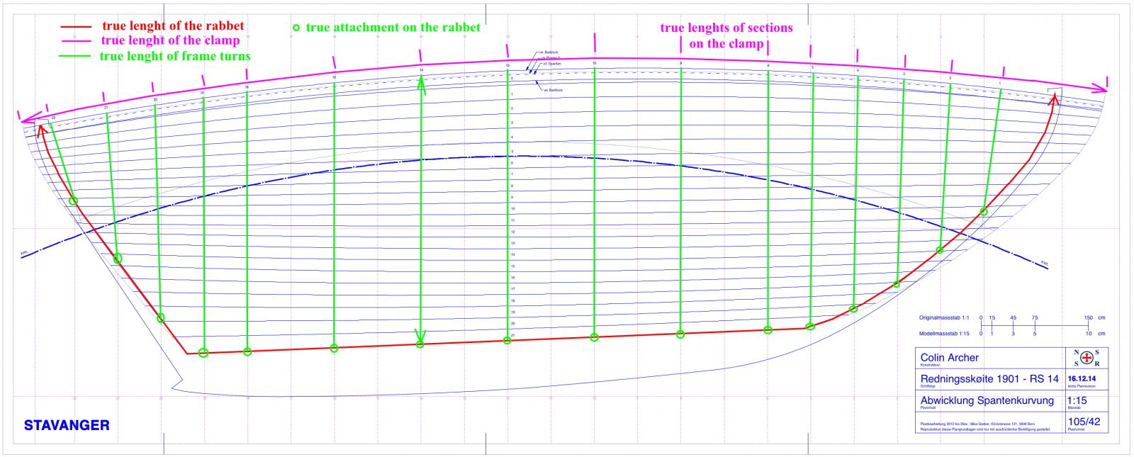
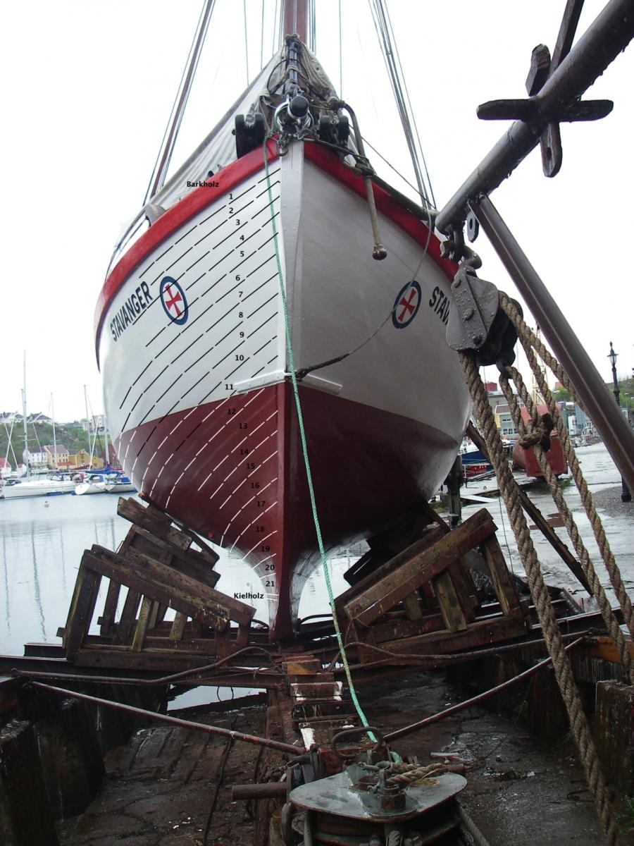
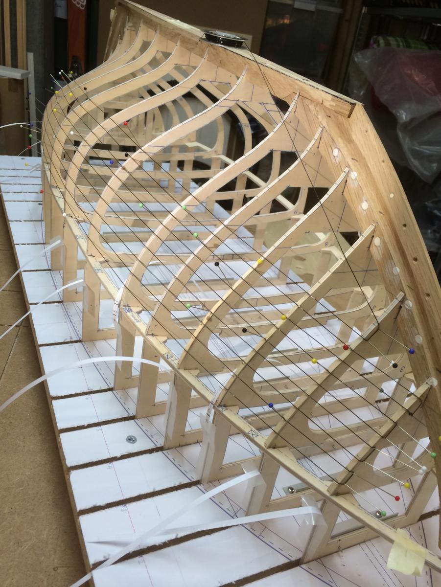
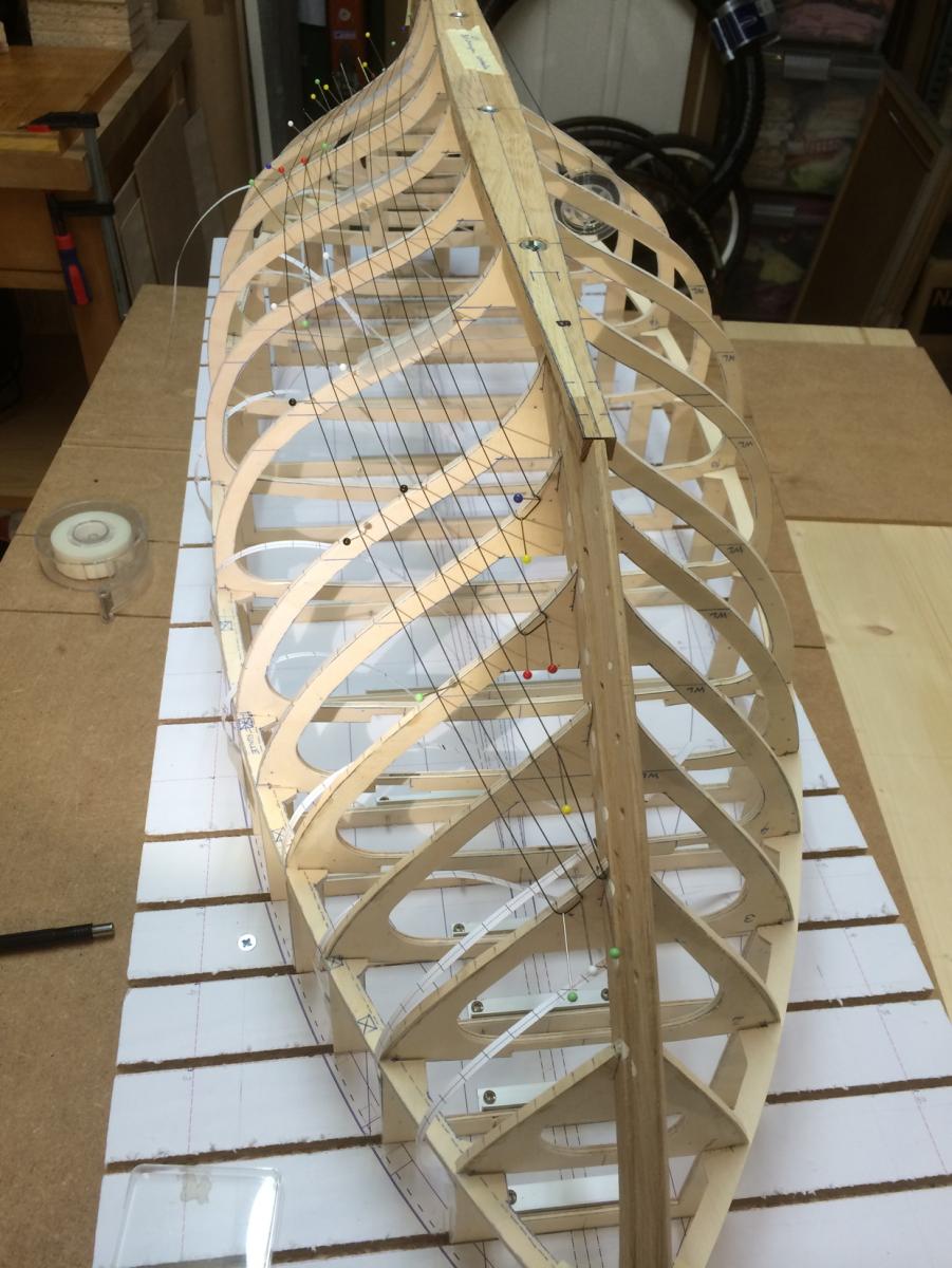
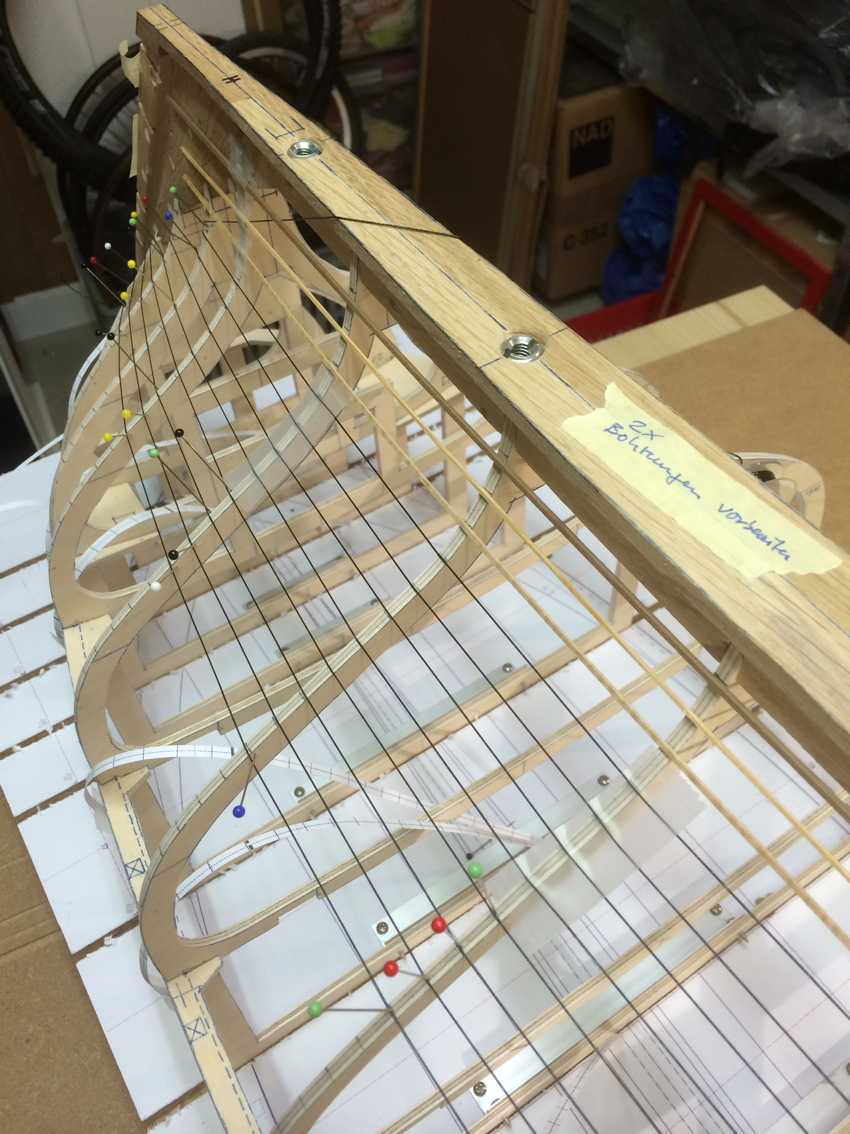
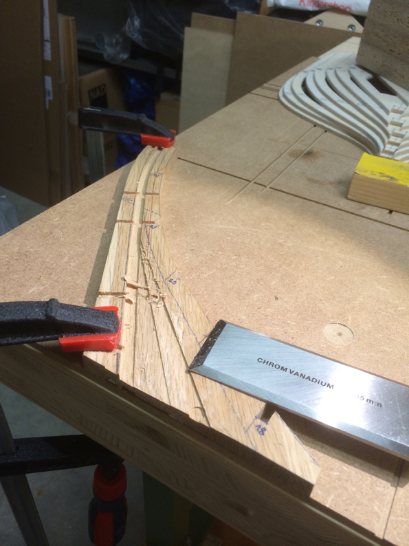
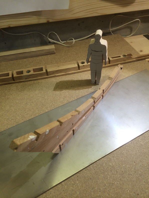
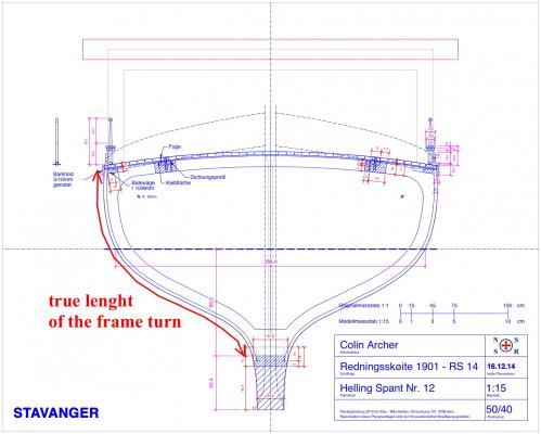
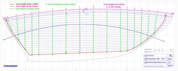
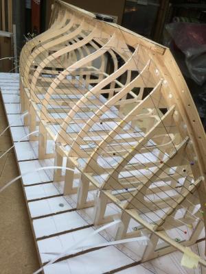
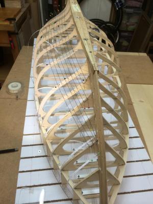
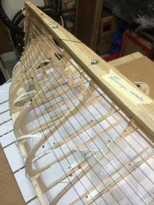
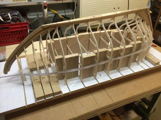
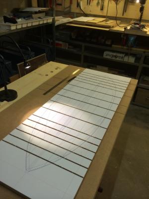
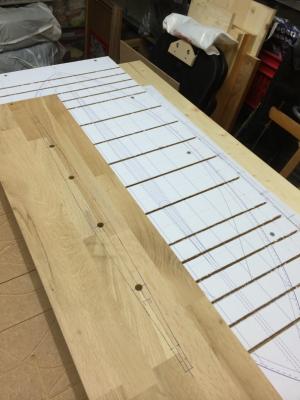
Hello everyone I must confess, I don't actually have experience in sheering/streamlining and planking, I do it all for the first time. So, please you'd forgive me, when all awkward therefore comes. The below described approach to this theme arose from a mixture of laziness (to create a full CAD-3D model), intution and analysis and especially on my lack of any other method. There is certainly a danger that all this is already known, and I am the last of all - then let me know. (Sheering/streamlining: I don't know the correct term in English, in German it is called “straken“. So, maybe someone can help me ... ). As I have mentioned this already above, I intend to plank the hull in original geometry. At the beginning I asked me the question, whether such efforts probably justifies, if later everything will be painted. Finally I persuaded myself to look at this whole procedure as an exercise - an exercise as regards a future project where I would need a visible course of planking. By the way, there is a other goal I try to reach, it is the attempt to grind not the whole hull round. Instead, I will try to save the polygonal character of the planking, if possible. I do not currently know whether this succeeds - we'll see... I made my plan studies only in 2D. Therefore I can't determine the exact plank geometry on a 3D-model. So, I was thinking about what has to be done to obtain a sufficiently accurate approach with little effort. So, I conceived a simplified representation of the off winding of the frames and planks. So, what do I know about the real geometry of the planking? What can we deduce with little effort from the 2D drawings? - I know the true shape and lengths of the rabbet. - Further, I can construct the true length of the deck edge on simple manner. Therefor I draw the clamp in its off winding and then I'll take measurement on the arc length at its outer edge. - Next I choose the lengths of polygon turns of the individual frames (without keel). In the next step, I project this determined true lengths in a 2D drawing. What I get here is a simplified flattened side of the hull, with almost real lenght of the rabbet, true length of the polygon turns (frames) and true length of the clamp outer edge. I pronounce it clearly: This is a simplified representation, since the angles and edge lengths aren't correct on the inside of the grid. This error based on the fact that in this drawing concavity and convexity of the hull are not sufficiently taken into account. I still hope that this drawing fulfilled my intention - the hope of finding a harmonious arrangement of the planks which can be applied to the model. Now, I have to drawn (by trial and error) up the plank hallways in a way, that the result shows a harmonic division. Narrow running planks on the bow and stern. Fan-like planks in concave surfaces. So finally I found a harmonious division of the planks - as intended. All this I have balanced with my findings, which I have received by studying the photos of "Stavanger": - Total Number of planks. - Number of planks above and below the CWL. - Direction of the plank joints. - Decrease and increase of plank widths. - Relations of the width of planks with each other. - and so on ... I must confess, I was not 100% sure whether the transfer to the model will really work with sufficient accuracy. Therefore trial basis, I've done a transfer of the division onto the frames and the entire model was sheerd/streamlined with a rubber thread. ... and it works! It works at least for the construction of my double ender. If someone would apply this method to a different hull form, I would be of course very interested in the result ... I am also interested in other methods of creation of a harmonious division on complex surfaces – certainly, questions and comments are welcome. Regards Mike


- 235 replies
-
- 16
-

-
Hello Patrick, hello Row Thank you all of you both for visiting - I like to pass the compliments to Colin ... Row, I was also thinking about braces but I'm currently working on the plank hallway No. 9 (counted from the deck) and the hull gets stiffer with each course - the bracing will not be necessary. Regards Mike
-
Ouch Michael! I look at the second image from the top and think to myself: The small decomposition of a swiss watch today looks less complicated - am I happy, that I have just an old pot on the workbench! You really are doing a great job with this build! will continue to follow ... Mike
-
Pen Duick 1898 by Mfelinger - 1:20
mikegerber replied to Mfelinger's topic in - Build logs for subjects built 1851 - 1900
Hello Matija To be slow is irrelevant - the result counts - your build is great! I will follow with great interest ... Regards Mike -
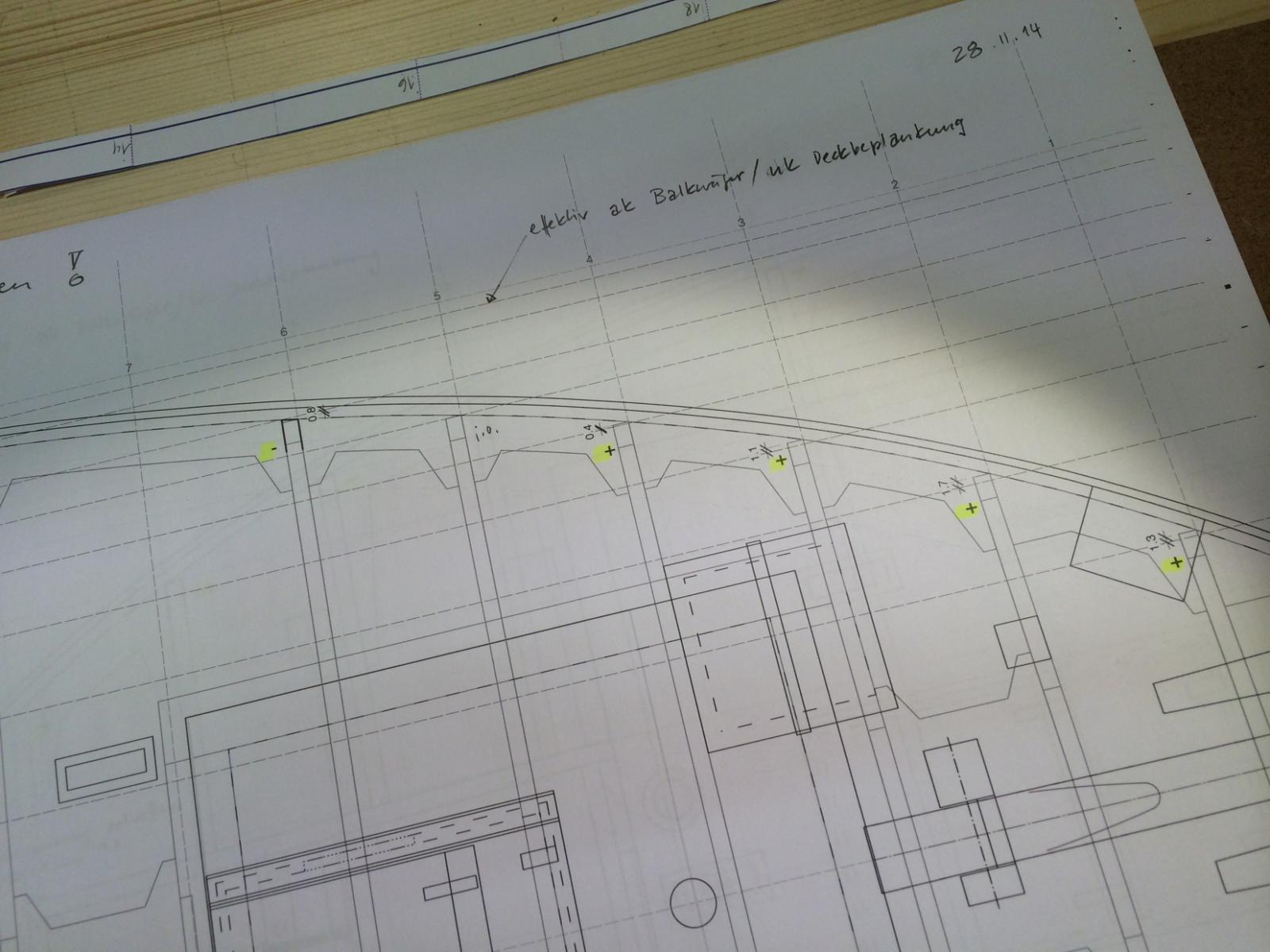
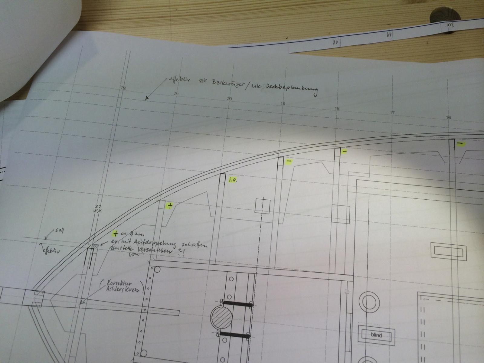
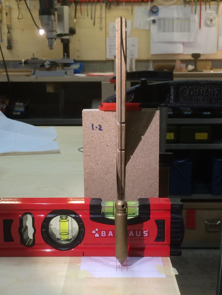
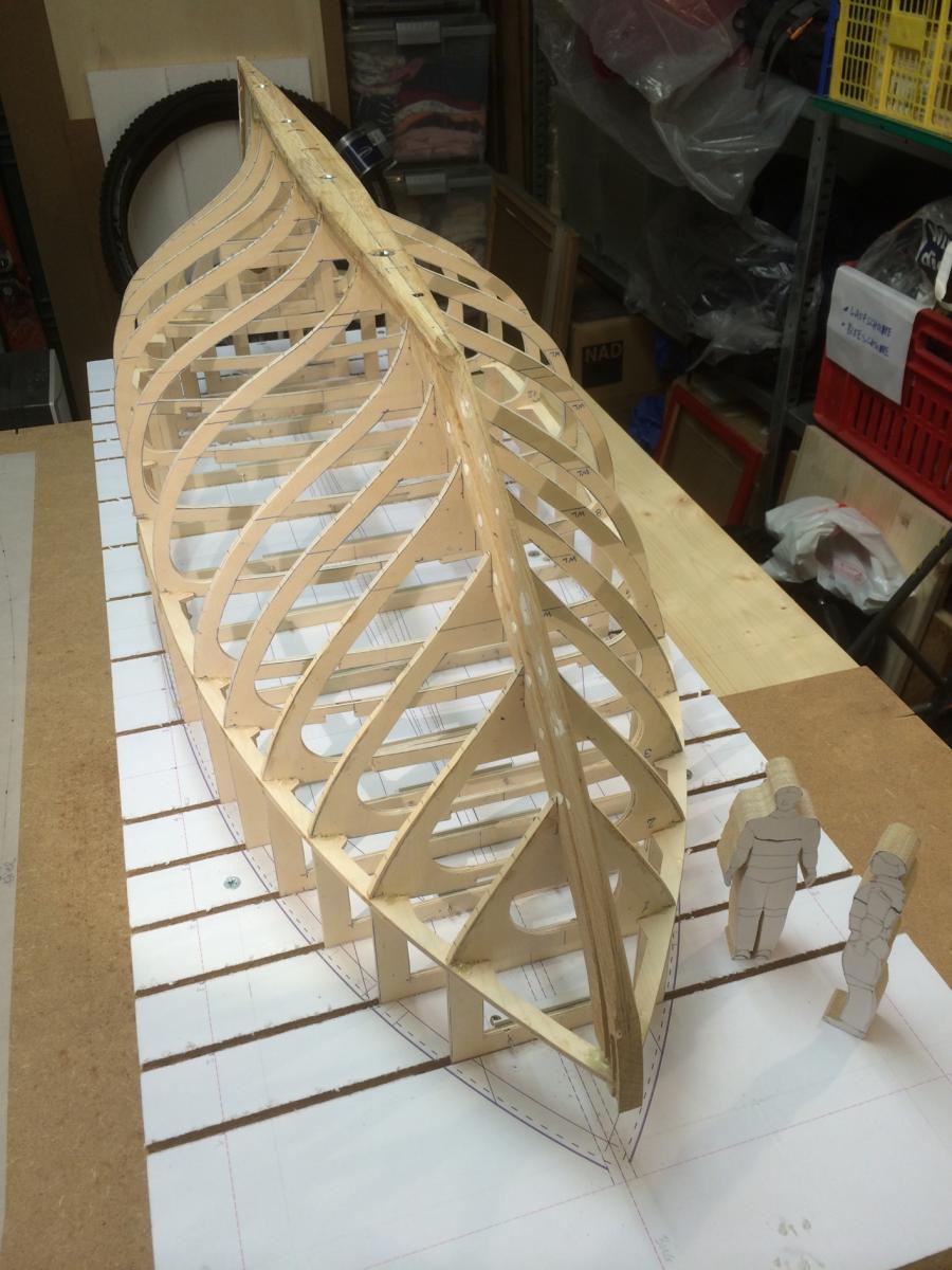
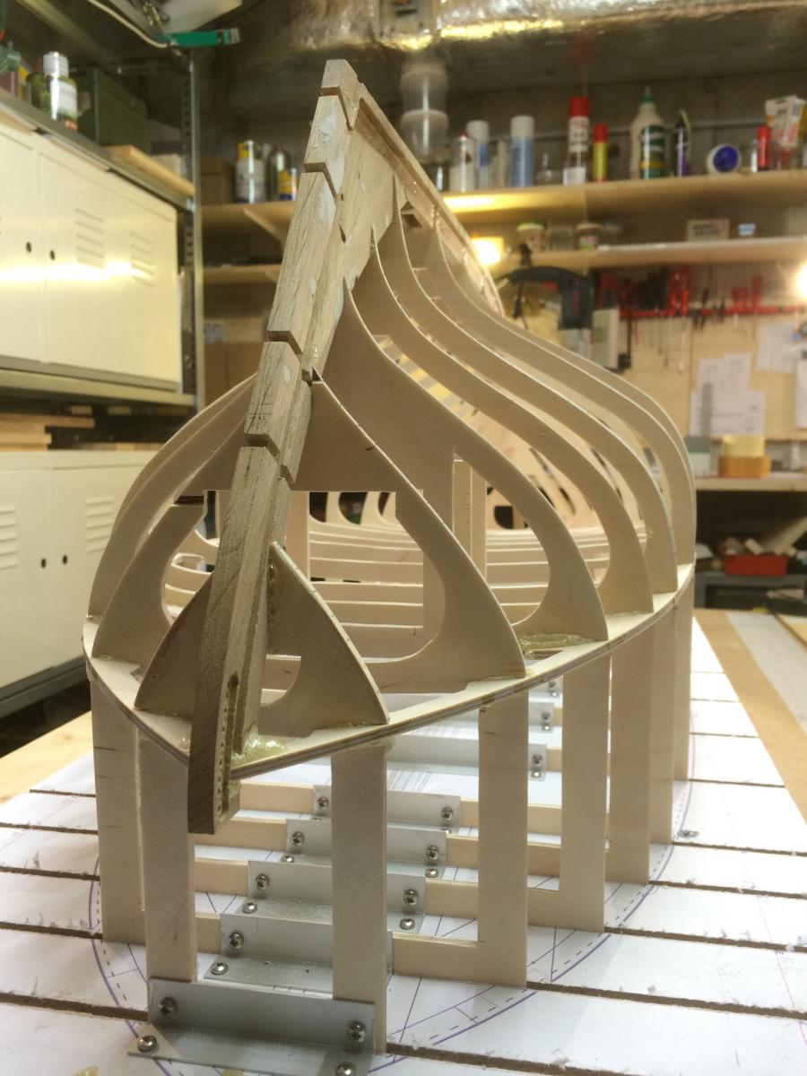
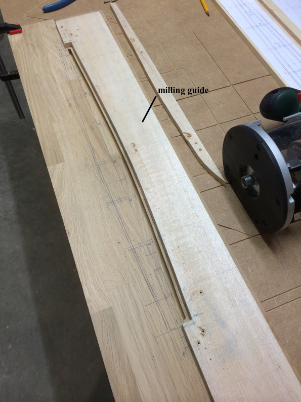
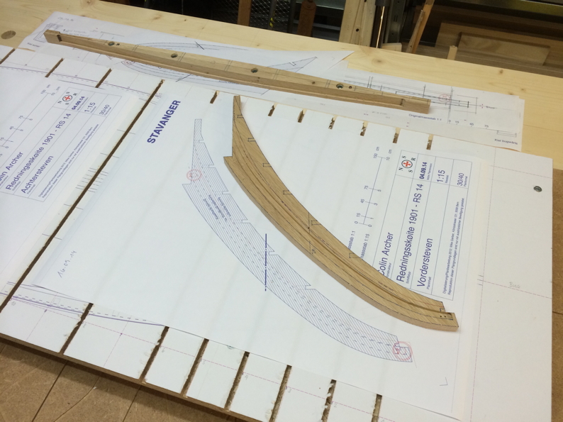
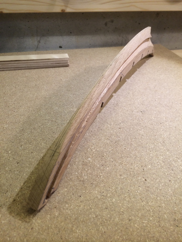
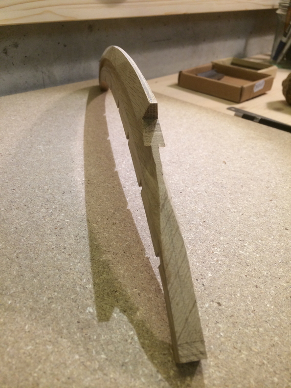
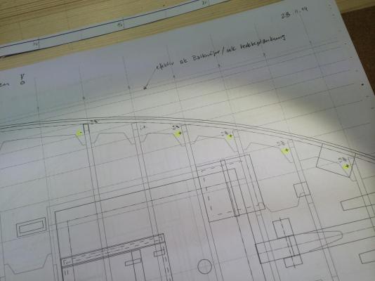
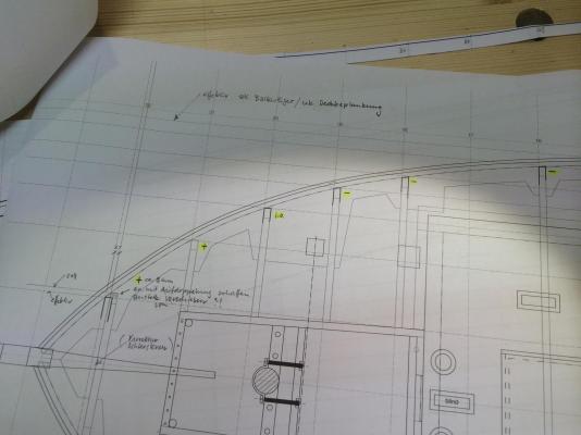
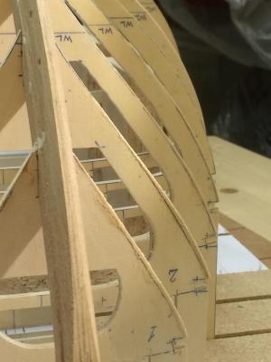
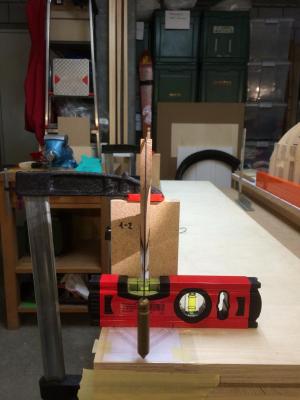
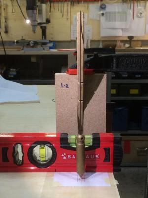
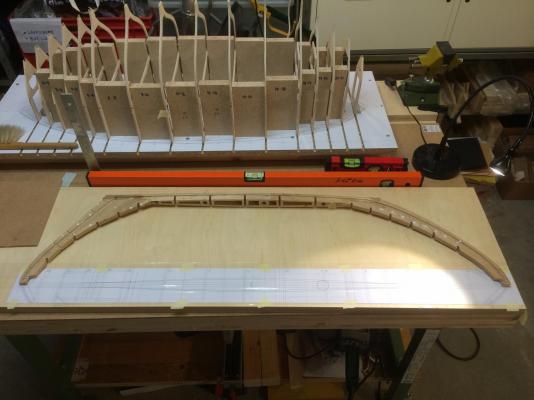
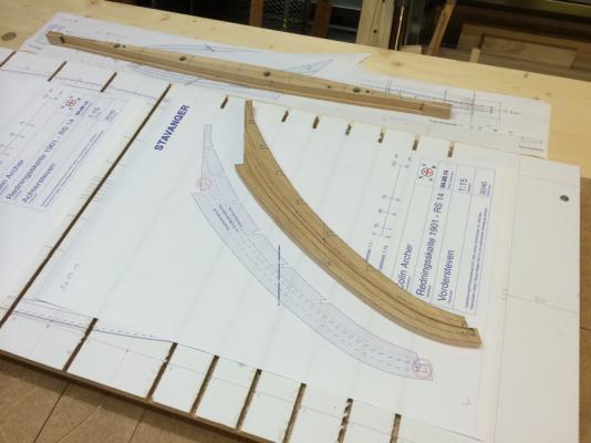
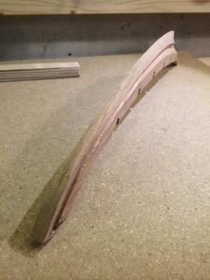
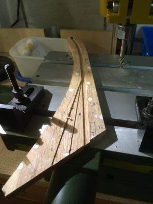
Ahoy! As you all have taken note, that in the last workshop-log, keel, stem and sternpost were already assembled to a unit. Therefore, I will make a short rewind on the appropriate step (see below). Later, by doing the last dry try, I remarked on some frames a difference between ’is’ and ’should’. On the appropriate parts, corrections have to be done – so this is the content of the following shown step. How this difference? During I checked the problem, I've noticed that the various old plans does not always correspond with each other. Further it happend often a insufficient resolution of the scans what are one part of my planning basics. The other part consists of numeric data, this way I was able to interpolate and doing some corrections. The next step shows the definitive Assembly of the structure. What we can already guess and on this I am looking forward as a little boy on Christmas, is the wonderful hyperbolic shape (saddle surface) of the deck! Regards Mike Below: Corrections and assembling of the structure. Lineup stem. Lineup sternpost. Lucky, assembly fits perfectly, length over stem and stern corresponds! Bow: Locations at which corrections must be. Aft: Locations at which corrections must be. Preparation of the duplication. Glueing the duplication. Corrections after sanding. Bow after final assembly. Bow after final assembly. Aft after final assembly. Aft after final assembly. ...

- 235 replies
-
- 15
-
-
Hello Elmir I was just admiring your Bracera - wonderful, congratulations! Regards Mike
-
Hi there @John Thank you for visiting my workshop - yes, it's probably what you're saying! ... and I'm sorry, called you incorrectly Jim, at my last reply - checked only the avatar's name. @Dimitris, @Michael, @Omega1234, @Nils, @Bob All of these great comments and many likes - thanks a lot! Nils, the keel is about 5kg. @Row Thanks for visiting and your great feedback! So, what can I say? ... however, it is really my first scratch build! Of course, I have very often built various types of models as I was a boy – but it was now about 35 years ago. At that time I have built especially R/C race cars and aircraft, but all without scale claim. By profession due to I have much to do with design methods and manufacturing processes and I was working by an architecture model maker for earn some money while studying. Currently, from time to time in my professional life I build architectural working models in card. So, these are my previous points of contact with modeling. ... Yes, I have read from the method with the freezer - and yes, we need once to check that. I would be pleased about your project of the saga 40 and I will follow it certainly. Oh yes, the similarity to ’Stavanger’ is obvious - a contemporary adaptation and a beautiful boat! Regards Mike
-
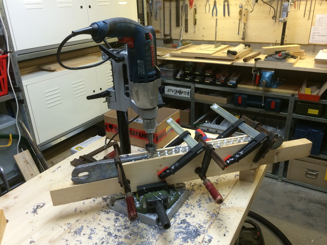
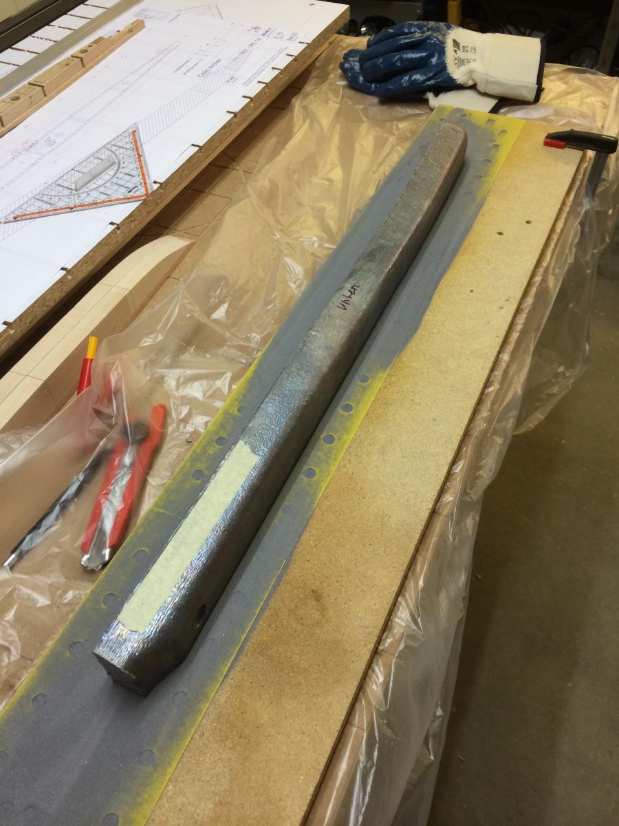
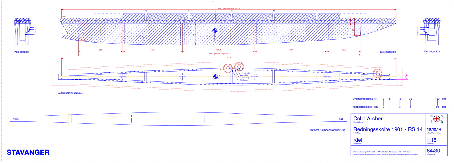
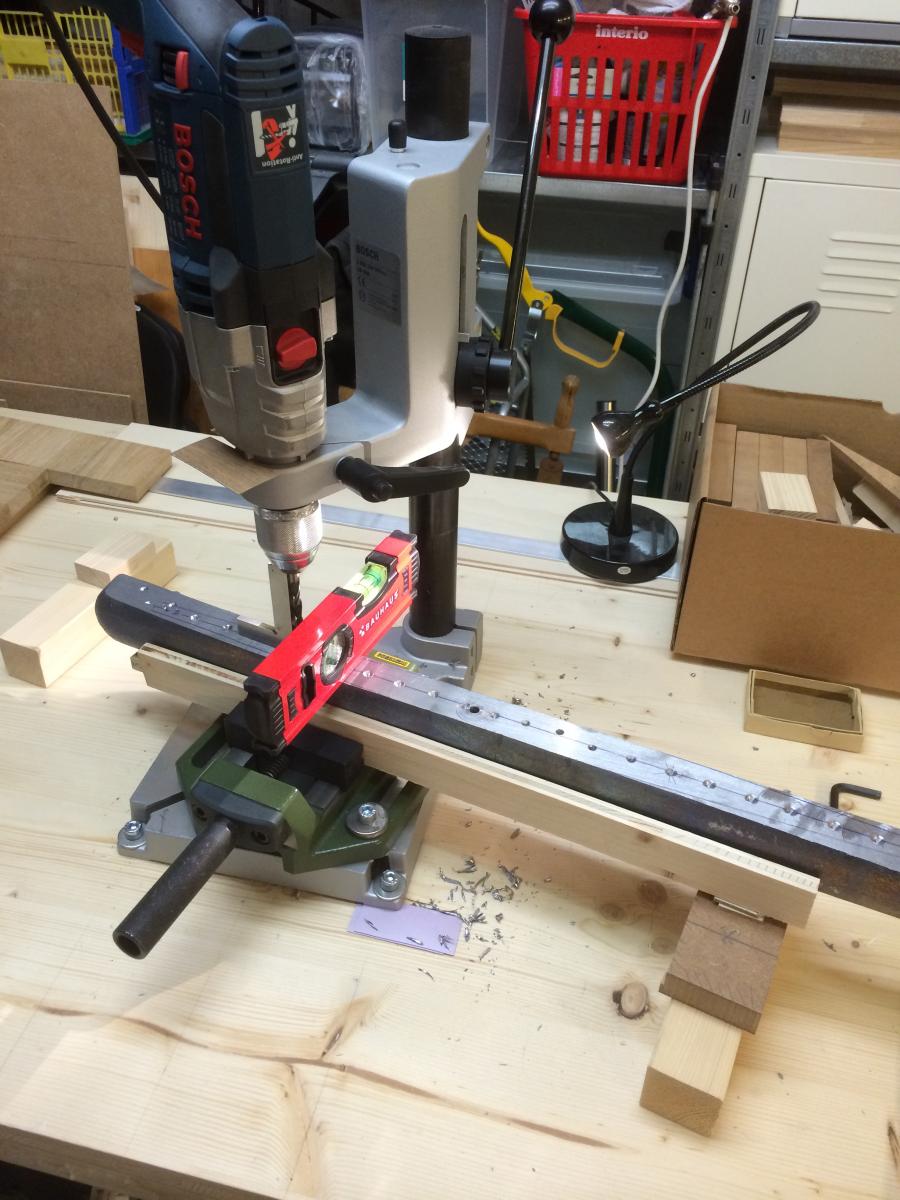
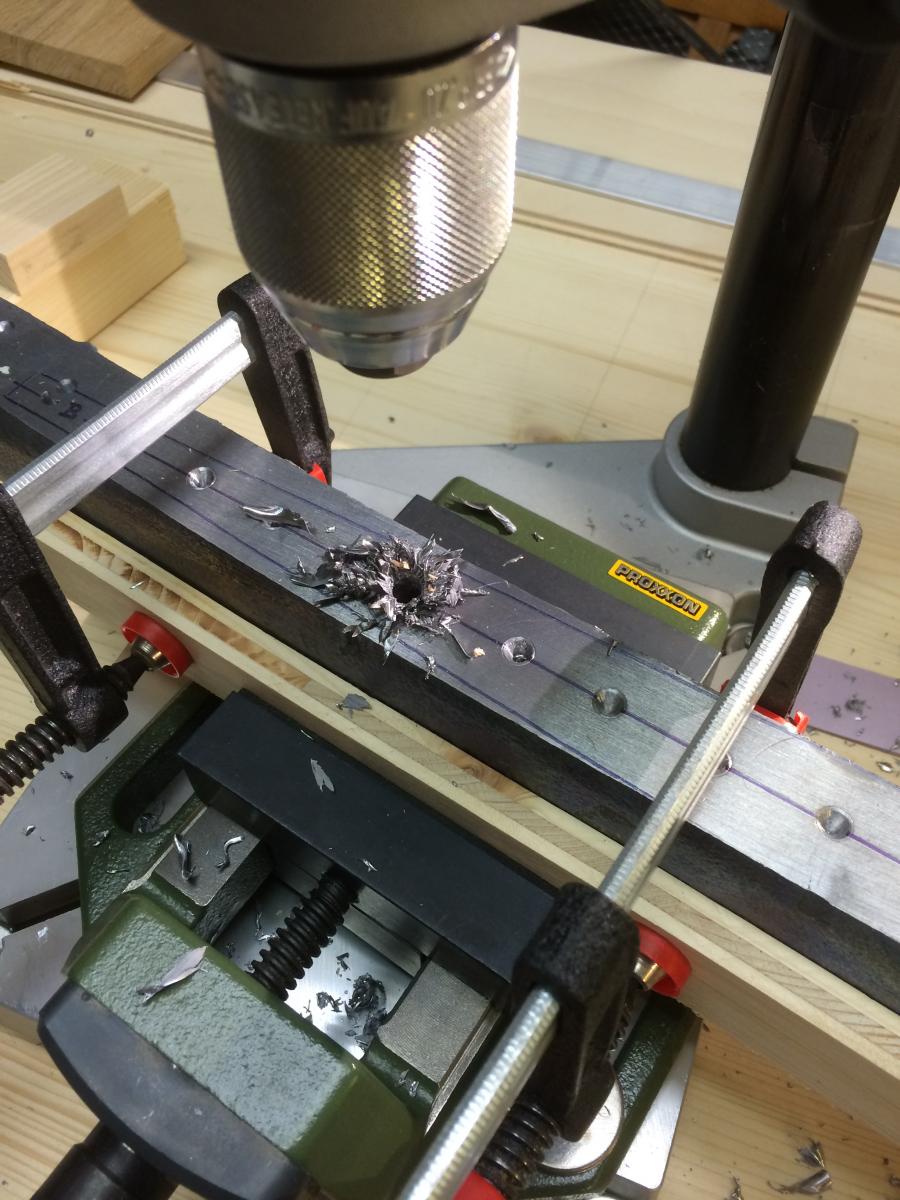
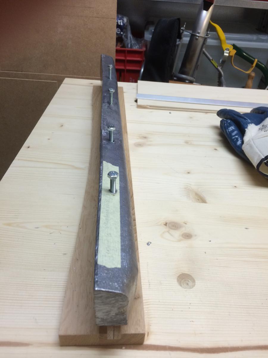
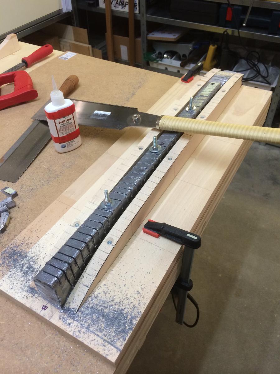
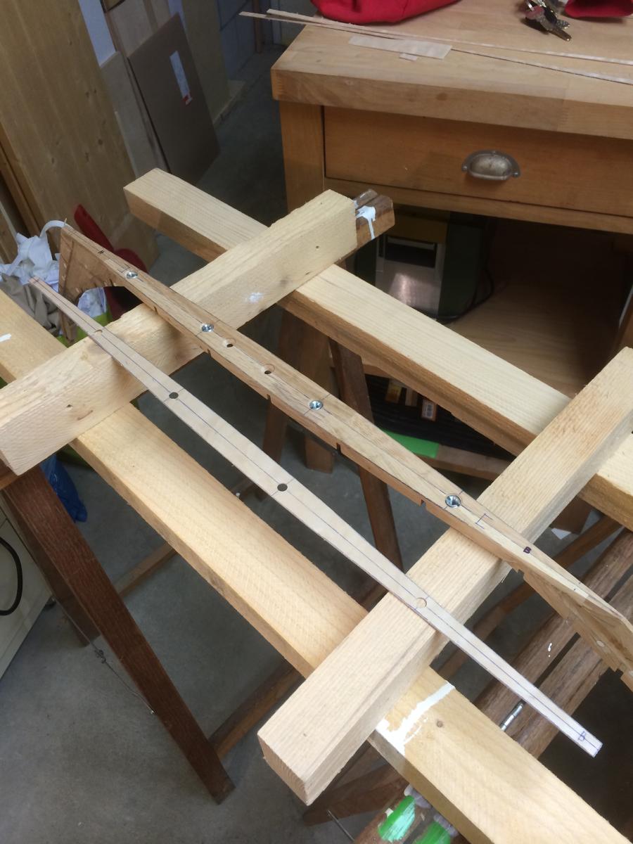
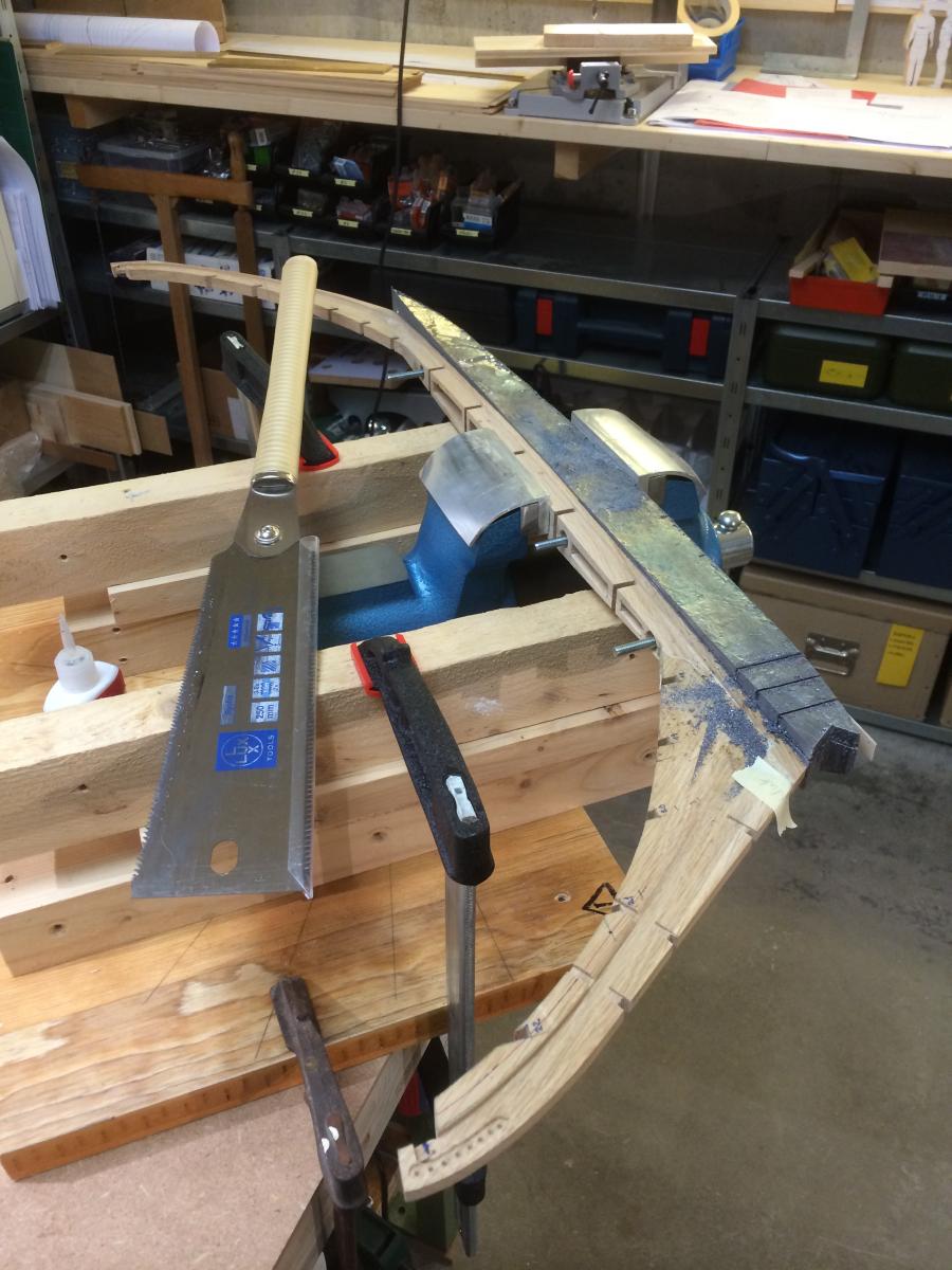
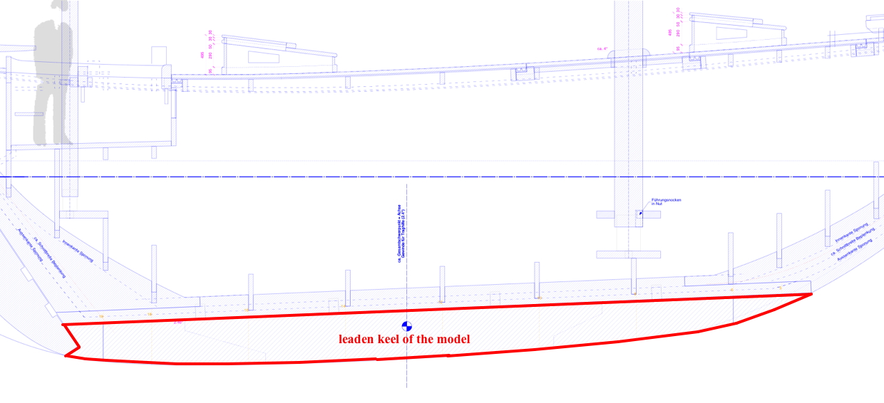
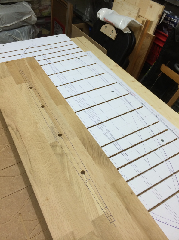
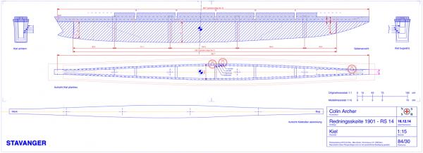
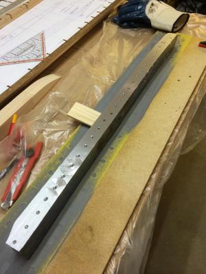
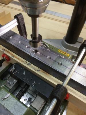
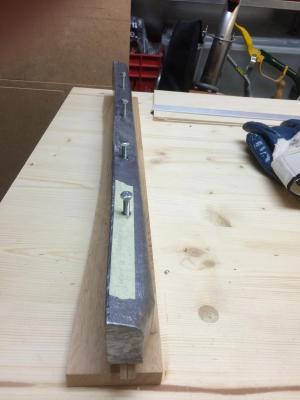
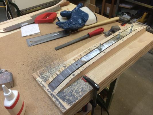
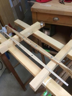
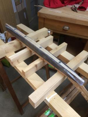
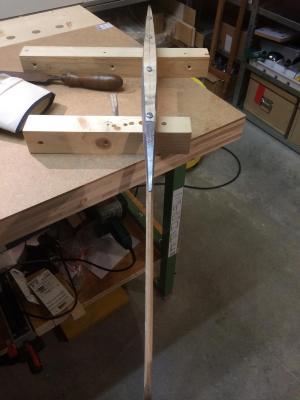
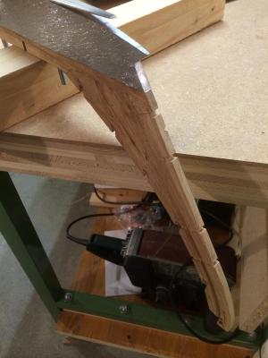
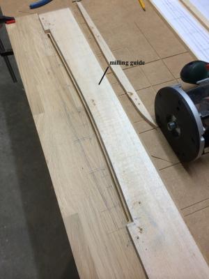
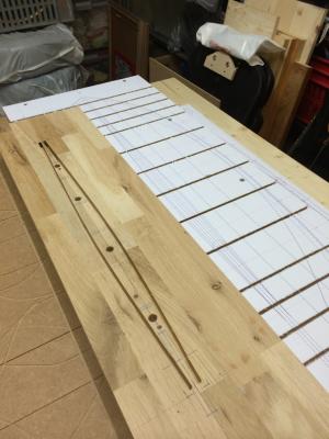
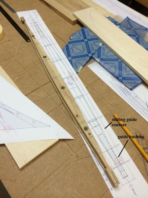
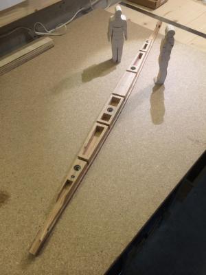
Thanks everyone for looking in, the comments, the infos, the questions, the likes! My next construction step concerns the manufacturing of the ballast keel. It is a lead keel and I've decided to cut these out of the full. Of course I thought also at a build of a casting mould and so on ... The idea that I have to melt the lead, the toxic fumes, the fireproof mould – I had too much respect for all this things. To say it right: By drilling and sawing, I have regretted my decision a couple of times. It is probably not the hardness of the material which is so laborious. It is the fact that the lead turns softer and softer until it almost melts by drilling and sawing. The tools are immediately bonded and will stuck! If any of you wants to drill or saw lead, these are the lessons that I've learned: Drilling: Little bit for little bit. Allow to cool down again and again. Drill on lowest speed with high torque. Provide chip flow. Best results with sharp wood working drills. Stay away from cutting oil! Sawing: Section split into small pieces. Use the sharpest wood working saw that you can find. Best result with Japanese wood saws with progressive course of cutting force. And now – use so much cutting oil as you can! Please use gloves and a dust mask, the lead is anyway toxic! Regards Mike Below: Manufacturing the keel step by step Longitudinal section, cross sections and plan. Leveling drill of the blank. Level grinding of the blank. Result of level grinding. Drilling of through holes. Melted chips. Leveling again. Check: All aligned - I'm pretty happy! Mounting the saw guide and cutting stages. "Done" part 1. Part 2 in preparation. Assembly of the keel and the saw guide. Work in progress. Result. "Done" part 2.


- 235 replies
-
- 13
-
-
Hello Bob I also devoured the book of Joshua Slocum ... and I like her, your "spray"! Regards Mike
-
Hello Bob Yes, you're right, I will probably need some space. It is the first time i build a R/C-sailor, so I will approaching this things from a maximum. Regards Mike
-
Hello Dimitris Wow! Looks great - congratulations! Mike
-
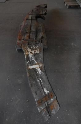
Good morning nils I have to correct myself: "... In the course of time many were fitted, so also the famous RS1 "Colin Archer". RS 14 had no engine until the end ..." From the year 1946 onwards, there was also a time where RS14 had an auxiliary prop - but i don't know the year when RS14 again was reinstated to the original. Regards Mike Below: The former rudder with cut-out for the propeller.
-
Hello Dimitris, Nils, Andrew, Michael I appreciate all your feedback - thanks a lot @Dimitris, @Michael Yes, I'm satisfied neatly with the skeleton. At the moment I'm working on the preparation of planking. It is my intention to provide the hull with original planking. This is a real challenge for me to get the right geometry ... ... and the double Ender shape also makes it not easier. I like to report you later about it. @Nils Yes, i will equip the boat with R/C. I've never done this bevor, so i'm curious. There will not be a prop, because i want to keep me as exactly as possible to the original. The first generations of these boats had no engines. In the course of time many were fitted, so also the famous RS1 "Colin Archer". RS 14 had no engine until the end. see link: make clear and take off (without prop) ... @Andrew It is of course a honor to me, to know a RS-Skipper in my workshop With interest I read your experiences with the RS77. And yes, i have read about it, in comparison with other tall ships, the RS-boats can keep up quite well - what of course says also something about the qualities of the skipper! Regards Mike
-
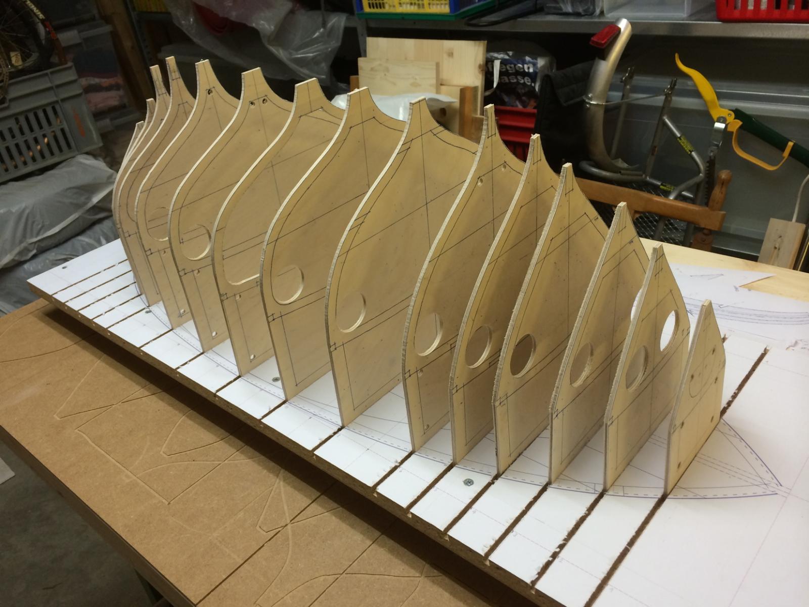
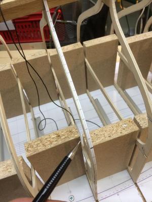
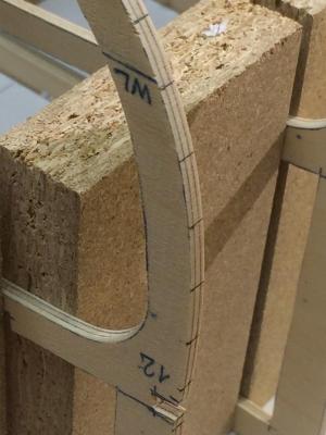
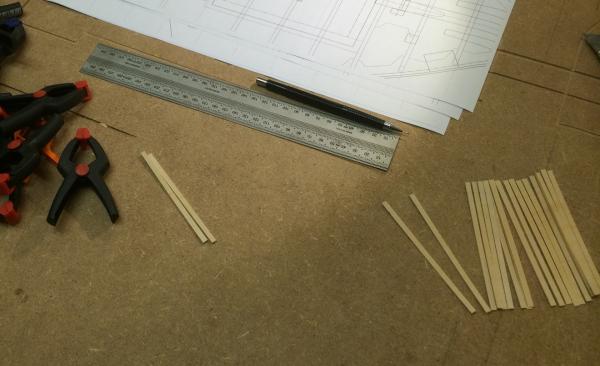
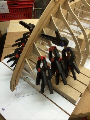
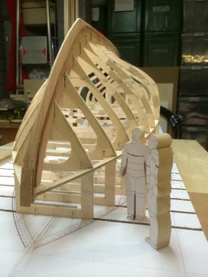
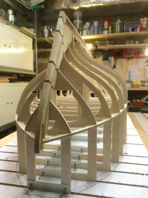
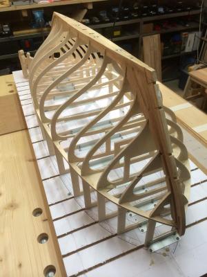
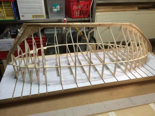
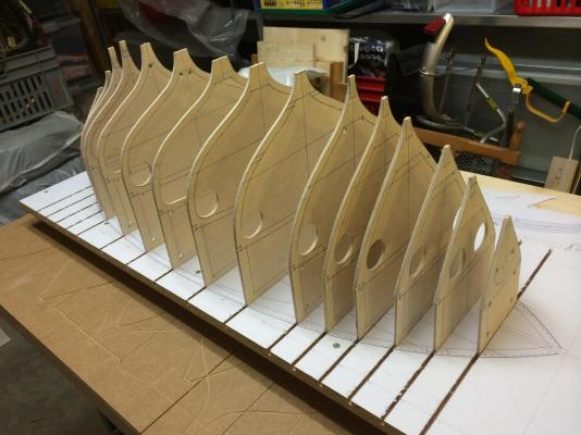
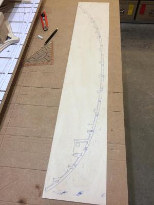
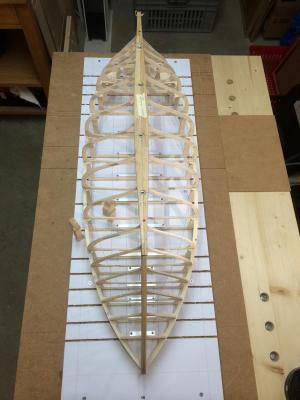
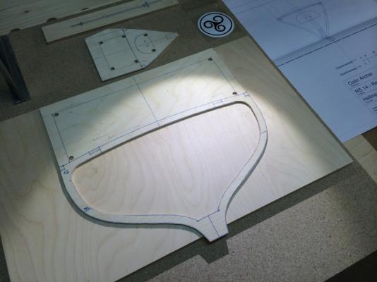
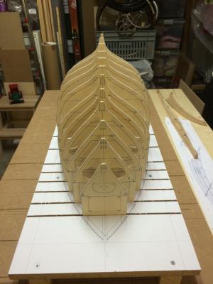
Hello again back to work in the workshop ... In the next step, the frames are now completely drawn on the plywood and sawn with the scroll saw. Also, the clamps are being prepared in 4mm birch plywood and and equal to the frames they has a model-technical shape. After that parts are assembled dry try. Keel, stem and stern are also unfinished and still in progress. The frames get well fixed and adjusted with aluminum angle. Chipboard blocks are be used as a temporary stabilization. Regards Mike Below: - some little progress ...
- 235 replies
-
- 15
-
-
Hello Michael Thanks for visiting and comment. ... certainly, i can well imagine it, i have read from your test – am sure, you'll have no stability problems in scale 1:8, she will sail as the original. I'm already looking forward to your first small pilot video movie ... Regards Mike
-
Hello Dimitris Thank you for your report on the lamination of the hull. For me it is helpful to hear from these experiences. I will following to see your build grow. Regards Mike
-
Hello Michael Already for a long time, I follow your logs and I ask myself all the time ... ... is there something you can not build? Your work is fantastic - pay tribute. Regards Mike
-
... and a few additions from YouTube https://www.youtube.com/watch?v=K_0rLzWY0jE https://www.youtube.com/watch?v=0olEb2xtg7o
-
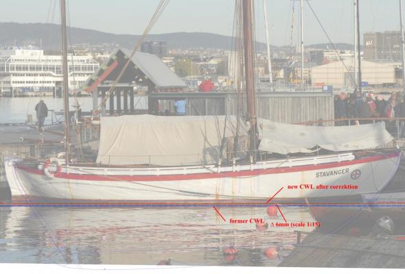
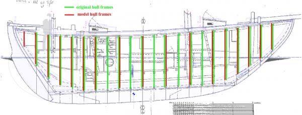
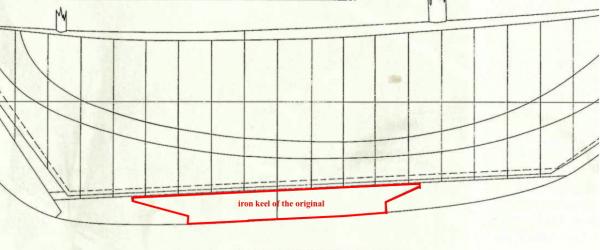
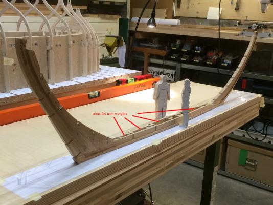
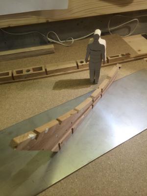
Hello everyone First of all, thank you for all your likes and views Now I would like to present a few thoughts i made about the RS14 as a functional R/C-model. It is common knowledge and the manner of presentation is somewhat technical. If it should get so bored or everything is known, then please ignore these post. Either way, for me these studies were helpful because they had a great influence on the choice of my design principle. It is my intension to make dimensions and geometry of the model same as the original. That means, to build a model able to sail without additional keel, etc. Further on the behavior how the model accelerates and turns has to be as close to the original as possible – in other words, it has to be slow. Such behavior is difficult to obtain in a model scale because the decrease in the reduction let the surfaces shrink only by power of two, however all volumes by power of three. This means, if we compare the original (1:1) with a model in scale 1:15 the displacement decrease 15-times more than the sail area of the model! So, the ratio of sail area and displacement is many times worse than for the original. Why is it so important? As we know, these old boat designs were only able to carry their large sail areas with the help of massive displacement. For a scale model, these ratio between sail area and displacement can affect super critical the sailing properties. At this point, i have therefore two questions to answer: What factors are in this context? 1) Selection type of boat and sail plan. 2) Selection of scale. 3) Distribution of total model weight. 4) Arrangement of ballast portion. What can i do to optimize these factors? 1) Selection type of boat and sail plan: From the beginning the subject was given to me. Someway, i fell in love with “Stavanger“. It could be only this boat and fortunately this type of ship is suitable as a scale model. This due to a favorable ratio between big displacement and a relatively small sail area. 2) Selection of scale: At this point, I had to check my intentions somewhat computationally. Experience has shown, that models with a specific sail area of a maximum ratio between 5 to 7 [sail area/displacement] in generally have sufficient stability and endurance at heeling, provided they have a high proportion of ballast. The greater the model (in the sense of model dimensions) is chosen the easier it will be to achieve this goal. I read about all this on various specific modelling web pages (http://www.minisail.ch, http://www.minisail-ev.de and more). So i've calculated ... Sail area (scale 1:15): 47.6[dm2] = 107.2[m2] / 15^2 Displacement according to John Leather’s book (see post above): 8.0[dm3] = 27’000[kg] / 15^3 = apprx. 27[to] / 15^3 Displacement by calculation based on my CAD studies: apprx. 7.0[dm3] Why this difference of 1[dm3] (corresponds to 3’375[kg])? Already for a long time, i suppose when looking at photo documents, that “Stavanger“ lies lower in the water as shown on old plan documents. If I'm not wrong with my calculations, the difference of 1[dm3] causes a lift of the construction water line (CWL) from apprx. 6[mm] in scale 1:15 - what could quite agree ... (see below: overlay with line drawing). So, i now have information about sail area and displacement in my chosen model scale. What is now the ratio called specific sail area (see above)? We know that a value of 5 to 7 want to be reached. Specific sail area (scale 1:15): 47.6[dm2] / 8.0[dm3] = 5.96 For the moment it seems to be more realistic to calculate with the described displacement of 8[dm3]. Anyway i will reach the required range with a model scale of 1:15. 3) Distribution of total model weight: My calculations for the intended keel design will result in about 5[kg] (Lead). The total weight is probably 8[kg], equal to the displacement. Further on experience has shown that a ballast portion of at least 60% of the total model weight is required to let those models sail well – so that looks good. My aim remains furthermore as much as possible to realize weight below the CWL and a light construction above the CWL. In this context i decided for the following measures: - Thin plywood frames (birch 4mm). Hence the decision to build the hull up-side-down. This way the thin frames are well fixed on the basic board. - Dimension and the number of frames are model technically justified (see below). - Ballast keel is maximized, wooden portion of the keels is minimized. the keel does not match to the original being this way – a R/C-model technical sacrifice that i have to take, but all less bad as the hull is painted (see below). - maximum deep position for trim weights (see below). - further i intend to optimize many other components above the CWL – of which i will report you later. 4) Arrangement of ballast portion: The ballast distribution influences agility and thus the appearance of the model. As it is my intention, the longitudinal arrangement of the ballast will have a straight course effect. As a result, the boat will less unnatural wobble as this is the case by a central arrangement of ballast, also its turnaround will be slower and is more similar to the original. Regards Mike Below: - Overlay with line drawing - Location of frames - Original keel design - Model keel design - Areas for trim weights

- 235 replies
-
- 10
-
-
Hallo Dimitris, Nils, Elia, Nigel, Mark I will following the discussion on the finish of the hull with great interest, i thank you for the valuable information, i need to learn much about this ... Regards Mike
-
Hi Christian I am delighted by your precise planning work, and analyses. I also struggle with varying informations on the RS14 "Stavanger" - i share your sorrows ... What CAD do you use? Regards Mike
-
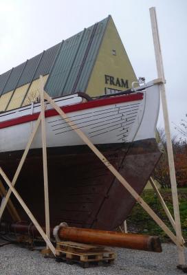
Hello again My studies and the beginning of the planning of “Stavanger“ go back to the year 2012. Again and again the work has been interrupteed by various reasons. But she was never out of my mind. In June 2014, i stumbled on NRG'S MODEL SHIP WORLD. Originally because of the sensational images of 'Le Fleuron' by rekon54. Browseing the NRG-page i found the pilot by Michael Mott what inspired me and what newly motivated my work on “Stavanger“ – now i was ready to start with the build. Mike Below: - start of the build - wooden part of the keel - stem - stern - raw frames


- 235 replies
-
- 18
-