

David Lester
-
Posts
679 -
Joined
Content Type
Profiles
Forums
Gallery
Events
Posts posted by David Lester
-
-
Bill - I didn't use the plastic for the windows. I have never used it on any of my models. I always just leave the opening. For some reason, I find it distracting to look at and difficult to install without getting glue all over it (at least in my case) so I always just opt to leave it off. I did paint the interior of the wheel house. I used a dark brown.
I haven't had a good look at the stack yet, but I do know that the supplied piece is pretty far off from being the right shape. I'm not sure how I'll approach it just yet. The small vents on the bottom of the stack will be pretty hard to do as the scale makes them only about 4mm long. I don't think I would try building them, I think I would be inclined to used a small piece of wood, the correct size, and suggest the vent slots by scoring the wood horizontally. These type of things I tend to experiment with and if the result looks ok, I use it and if not, then I omit it.
The box on the back of the wheel house is an easy detail to replicate, so I will probably add it.
The ladders! I have spent the better part of the afternoon trying to make ladders that look better than the provided ones, but I'm having a lot of trouble. I've tried some small brass strip for the sides. I drilled a series of holes and then soldered in brass wire representing the steps. Unfortunately I am the world's worst solderer and the result was quite a mess. I then tried using brass wire for the sides, soldering smaller brass wire across for the steps. Again, quite a mess. There are always two possible outcomes for me - a joint that fails or a glob of solder the size of a golf ball. So, I am still contemplating my options and waiting for another one of my 3 am revelations. 😄
David
-
Small update this morning -
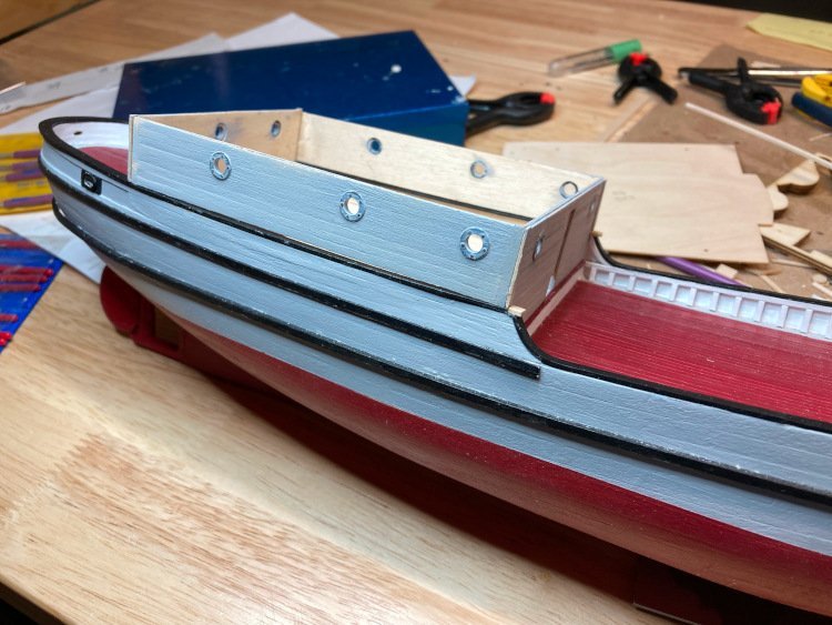
I've been working on the wheel house.
The first thing was building up the depth of the roof -
Then the assembly was quite simple. The walls are made out of very thin plywood and I didn't like the idea of the exposed edges, so I applied a narrow strip of Tamiya tape over the joints, which both hid the raw edges and more or less replicated the look of the real thing.
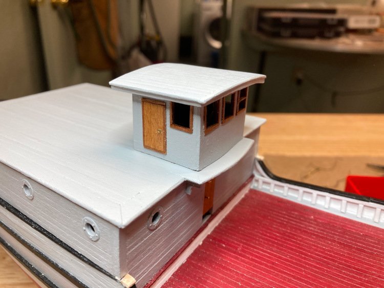
I noticed that the real wheel house has one operable window, while the rest are all stationary, so I tried to replicate that with the cross bar in the one window. You can't see it in this picture, but I also added an actual steering wheel, which you can see when looking straight one.
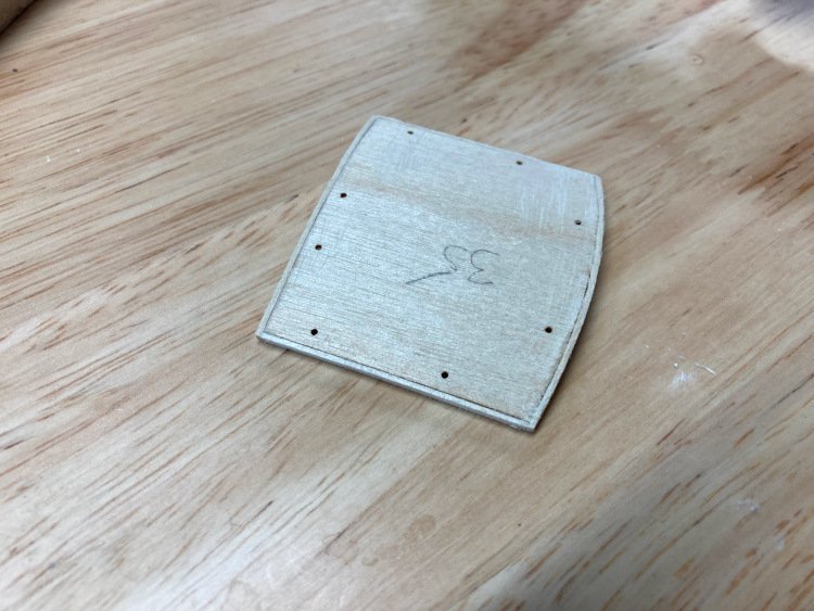
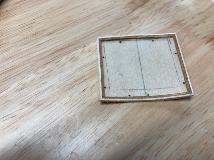
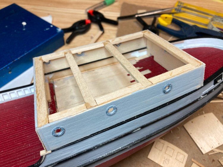
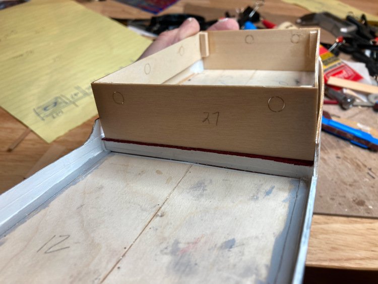
I also built what is referred to as a cargo scow. I assume it's designed to be towed across snow/ice. It has curved ends and sits on runners. For some reason the kit shows this component as a simple box.
It's shown below along with the hatch, both of which are not installed yet, but just sitting in their approximate locations.
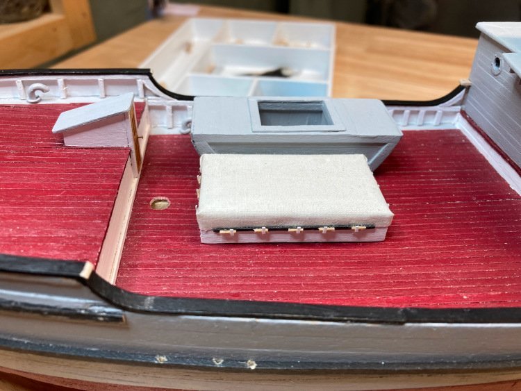
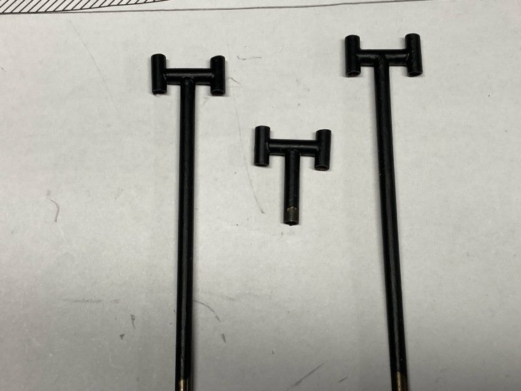
You can also see two of the six gooseneck vents which are not included in the kit. I bought some from Cornwall Model Boats and cut them down to size -

I also made the three water outlets, which are not included in the kit, using the valves which are not needed for the vents.
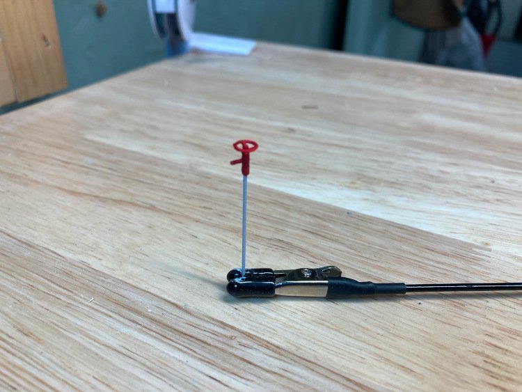
To make these I used some 1mm brass rod and some brass tubing just big enough to fit the brass rod and the stem of the valve.
That's it for this morning. I'm currently working on a number of the other small deck details.
Thanks again for checking in!
David
- GrandpaPhil, James G, Knocklouder and 4 others
-
 7
7
-
Thank you. It was a bit of a surprise to me that the mitres came out as well as they did, because the deck house isn't square. I pinned the boards down first without glue, overlapping them at the corners and marking the intersection points. To my amazement, it seemed to work!
Thanks again,
D
-
So, here are some pictures of my progress.
I wanted to replicate the steel cladding on the hull and wasn't sure how to do it. I ordered some thin foil, but unfortunately when it arrived, it was much too heavy to manipulate, so a thought occurred to me, and here is the result:
I used masking tape. The beauty of it is, it will stretch in more than one direction. I don't know what the longevity of it will be, but to be honest I don't care. I'm old and realistically, how long does anyone need this thing to last?
I represented the nails, or rivets, or whatever they should be called, with a mechanical pencil with no lead in it. It was the ideal tool to make the round indentations. They don't show up too much from a normal viewing distance, but just enough.
First, I built up the raised area
Then tapered it.
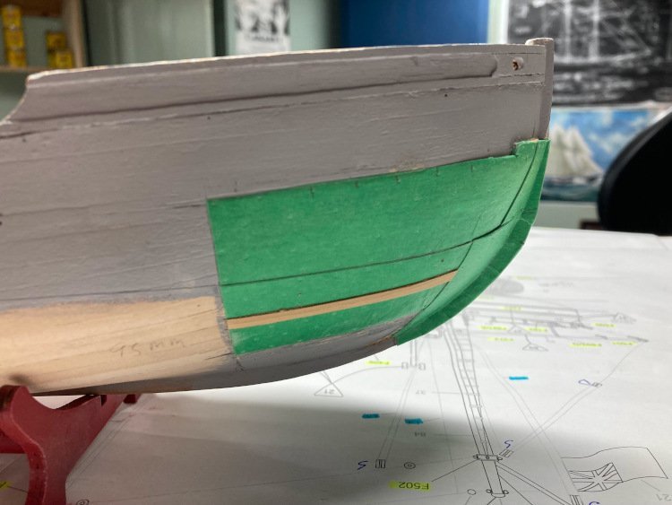
Then I applied the masking tape, trying to duplicate the actual pattern, and used multiple layers to get the effect needed.
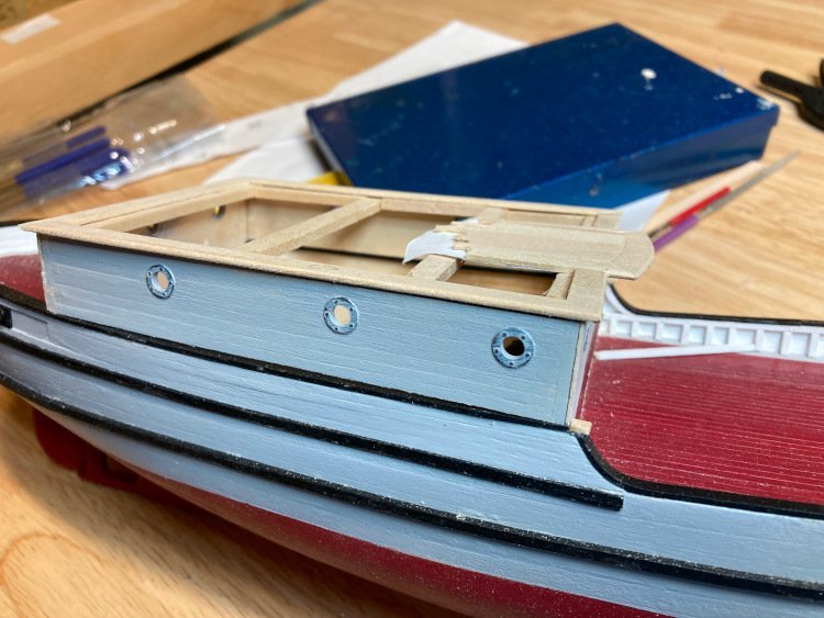
Next up was the deck house. This was actually a bit trickier to position correctly than I anticipated. I planked each of the four walls first and after a quite a bit of swearing, got everything more or less square and secure.
The plastic port holes are going to look just fine. They need another coat of paint, of course, and I still have a bit of "corner work" to do.
The roof had me concerned for a moment, It's a one-piece sheet of thin plywood, which is intended to be planked. My concern was how to treat the edges. On the real boat, there is a nice overhang on all sides, which is finished with a bullnose. There was no real overhang with the provided roof and I wasn't sure how to treat the edges, so I decided to discard the plywood roof and thin planking, in favour of using heavier 1/16" x 3/32" planks for the centre area and 1/'16" x 1/4" planks for a frame. It was easy to give the 1/16" stock a nice looking bullnose.
First I added some framework.
The I rounded over the outside edge of the edge pieces.
I handled the centre section, where the pilot house sits, separately.
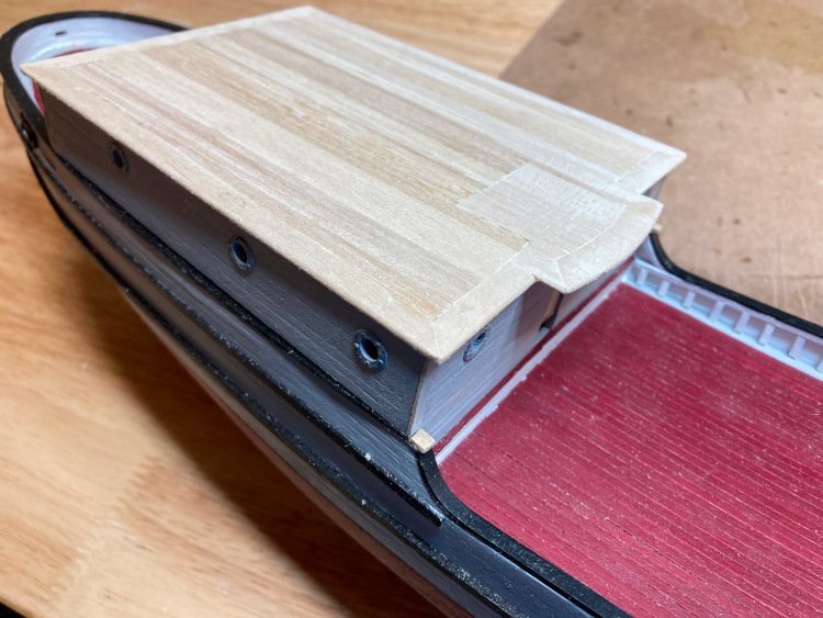
Then I filled in the rest and it's ready to be painted and have the crazy complicated collection of things added on top.
Many thanks for checking in!
David
-
Hi Bill,
Sorry, I just noticed your post now. Yes, I have planked the deck house and will be posting pictures later today.
I too have been thinking about how best to add the fire hose. One thought I had (they come to me at 3 in the morning) is to use some sail material from another kit. I'll coat one side of it with watered down glue, so it doesn't fray like crazy. Then I thought I would cut a narrow strip, let's say about 1/4"wide, then fold it over along its length, making it about 1/8" wide. This will leave a rounded edge and a raw edge. Then roll the strip up, placing the folded, rounded edge out. I don't know yet if it will work, but that is what my first attempt will look like.
The real fun of this kit is the many missing details that can be added. Thank goodness for that 360 tour on the museum website.
David
-
I'm not sure if I mentioned it in my build log or not, but I left the bottom piece off and using a fine hand saw, I cut the whole thing in two, running the saw stem to stern through the centre. It made it much easier to sand the interior and it glued back together perfectly. I can't take credit for the method however; I read it on another build log, but I can't really recall which one.
David
-
Steve - I had a very unpleasant day to day, but your comment completely turned things around for me.Thanks for that!
As much as I loved building this model, (in fact of all the ones I've done, this was my very favourite) I really hated doing the boats. There just doesn't seem to be any way around them. And there are so many of them!
I'm sure yours will look great.
David
-
A quick update today -
I've been working away at a variety of things.
I've added the stanchions (which are not part of the kit's plans) including the curved transition piece where the deck levels change. This recreates the actual boat quite closely. The stanchions are much closer together in the centre part of the boat and further apart at the bow.
I've also been working on the decking.
I didn't use the provided decking material, which is that .5 x3mm stuff of indeterminate origin which I don't like very much. Instead I used some 1/32" x 3/32" basswood. The decks on the St. Roch appear to be painted, so that's how I finished these decks too. I have never painted a deck before and I was afraid that it would completely obscure the planking, so I tried something I've never done before and that was to paint the planking before installing it. It's not likely that I would ever do it this way for a deck that was finished in one of the more usual ways, but for this painted deck, I think it worked quite well.
I also added waterways, which the kit doesn't provide for, but I did make a compromise. On the actual boat the waterways sit higher than the decking, but I have opted to make them all level. With the slightly thicker planking that I used, It was getting a bit too tight along the bulwarks if I made the waterways any higher than I did. This is a small compromise that I can readily live with.
A couple of other little things -
I made the chimneys from scratch using 3mm brass tubing. I am really bad at soldering and don't really like doing it very much. However after several stabs at it, I managed to get an acceptable result.
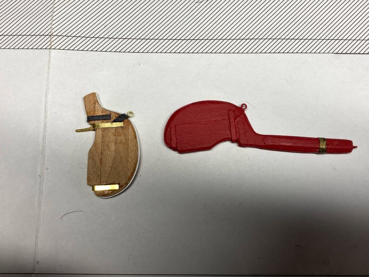
I've finished the rudder, which is now ready for paint, as well as made a spare one to sit on the deck, as per the actual boat. The kit doesn't reference this spare rudder, but it does provide two rudders. The spare had to be modified to be made longer as the one to be installed on the stern only just reaches the bottom of the hull.
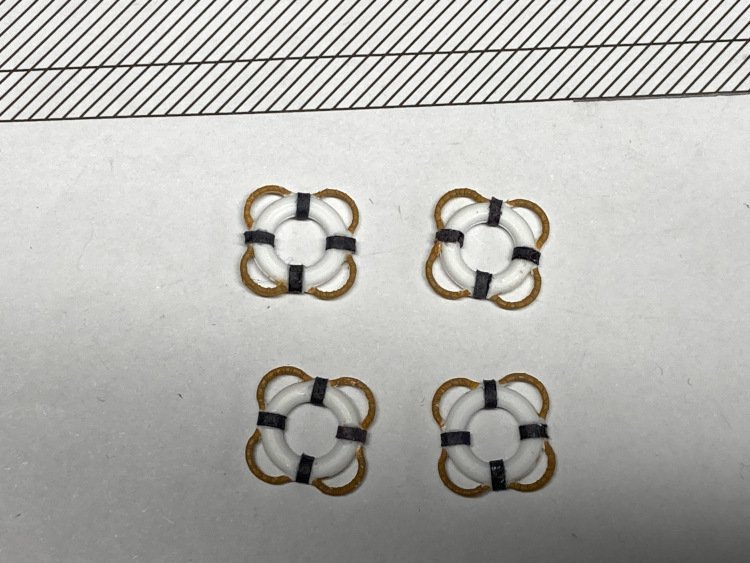
The kit provides four life rings which are plastic and I decided that once they were painted up they looked as good as any cast metal upgraded version would. So I chose to use these ones rather than replacements like I'm doing for so many of the other fittings.
That's it for tonight. My next challenge is to try to figure out a simple, but effective way to replicate the steel sheathing on the bow of the hull.
Many thanks for checking in.
David
- woodartist, Scottish Guy, Diver and 7 others
-
10
-
Good Monning,
Look what I am the "lucky" recipient of -
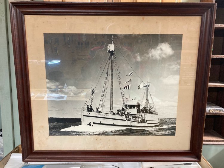
I have a friend who is interested in all aspects of history, but especially naval and military history. When I mentioned to him that I was building St. Roch, he was the first person I had spoken to who knew the vessel I was talking about, knew its history and even knew its captain's name. Furthermore, he said he had a picture of it that I needed to have (or he needed to be rid of, I can't quite remember.)
For some reason my wife does not want to see it hanging over our fireplace, so I guess it will be my basement shop for the time being.
David
-
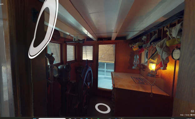
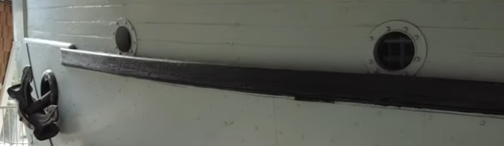
I found these pictures, which answer the question about the location of the steering wheel -

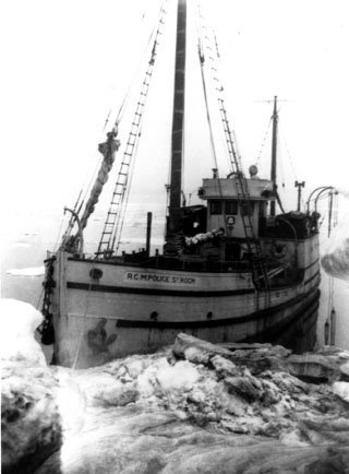
But there seem to be unending questions:
In the pictures above, which would seem to be about the same era, the first one shows three port holes and the second one shows two. Also the planking around the lettering is different.
The boat has clearly had several rebuilds, in which it has been changed considerably.
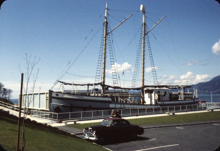
This picture is supposedly from 1928, the year it was launched:
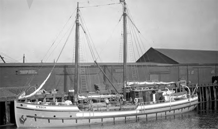
It had a totally different masting and rigging, three port holes, no cabin, I guess that's a pilothouse, big cowl vents, different paint scheme etc.
But by the time of its Northwest Passage days, which were in the 1940's it seems it was altered to looked pretty much the way it does now, but then here's a picture from probably the 50's and it's been rebuilt again, closer to when it was launched, but still differing in several ways - the pilot house is different, the port holes have gone from three to two etc.
I'm guessing they restored it to look like its Northwest Passage years when it went on display at the museum, but that still leaves the question of why the steering wheel isn't there. They obviously made choices at the museum, but I'm not sure what were the deciding factors for those choices.
I haven't found any narratives on-line yet that outline these changes, but I'll keep digging.
David
-
Hi Bill,
I have noticed both early on and to be honest, haven't really given it any thought since. It's a bit confusing, isn't it?
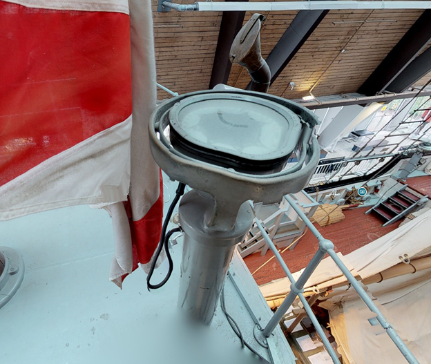
I think this is what you are referring to on the top of the pilot house, but it doesn't look to me as though the canvas-covered structure is large enough to contain a steering wheel; certainly not one as large as the one shown in the historical picture. Also the historical picture shows a wide base rather than a column. (It also shows a cowl vent which the boat doesn't currently have.) Clearly changes have occurred over the life of the boat.
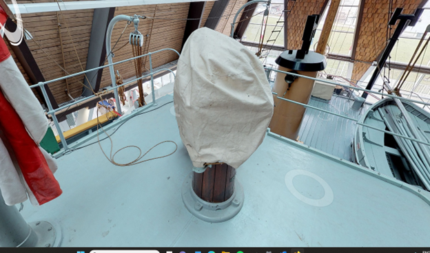

Another question - if this is a steering wheel, there appears to be no mechanism to connect it to the rudder. There's nothing visible on the ceiling of the pilot house. This leads me to suspect that the canvas-covered structure is not a steering wheel, but if that's the case, I don't know what it might be.
I may be showing my ignorance here, but there's another thing on the roof that I can't identify -
Any ideas of what this might be?
David
-
Thanks everyone for your input on the placement of the portholes vis-a-vis the rubbing strake. I believe most of you favour placing the portholes so that they just clear the rubbing strake and I think that's the way I will go. I think if I place the rubbing strake over the portholes, it will look like I messed up somewhere along the way, (and since that never happens 😁, why suggest that it did!)
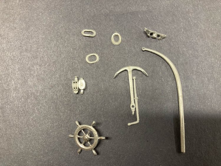
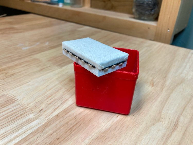
Bill, your St. Roch is coming along very nicely. You asked where I found the trim for the hawse holes. They are a BlueJacket fitting. Here's a picture of the fittings I bought from BlueJacket.
BlueJacket calls them hawse lips(F0743.) They're in the upper left of the picture. The lower one is how they come and the upper one is after a little squeeze to more closely resemble the real thing. The others are Hawse lips for the anchors (F0451.) Also there is an anchor for the deck (F0506,) the davits(F0071,) these are not quite the right arc, but can be easily bent into the right shape. They are a bit too long, but I can either cut them off or sink them deeper. Chocks for the rail (F0089,) and blocks. The blocks on the real boat are all internally stropped. These ones (7/32" - F0378 and F0403) will work well. I'll paint them. Also, I decided to add a ships wheel (F0291)which I think will be visible through the window.
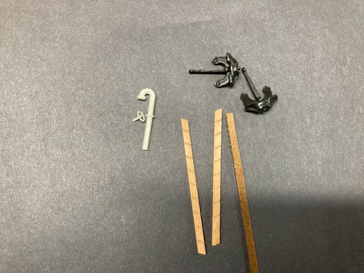
I also added a few things from Cornwall Model Boats. On the real boat there are six gooseneck vents along the waterways, which are not included in the kit. I thought I'd try these ones. I'm not sure that they're quite right. As small as they are, I think they are still a bit overscale. My plan B is to make them from scratch using pieces of 3mm solder that I have kicking around. (It's about 40 years old and dates from the days when I was still suffering from the delusion that I could successfully accomplish my own plumbing repairs.)
Even if I don't use those gooseneck vents, there's another reason why I bought them and that was to get the valves that come with them. They aren't needed for the vents, but another detail that can be added is the two or three water spigots. These won't be hard to make from scratch, but the valves would be. These ones should work for that quite well.
I also bought a ladder kit as well as a couple of anchors for the side of the hull.
I mentioned in an earlier post that although I generally don't like the plastic parts included in the kit, I actually prefer the provided plastic portholes to the provided brass ones. The plastic ones match the real ones quite accurately and since they will be painted they should look just fine. Cornwall offers these, so I bought a few more to replace the brass ones, which I think have too big a rim.
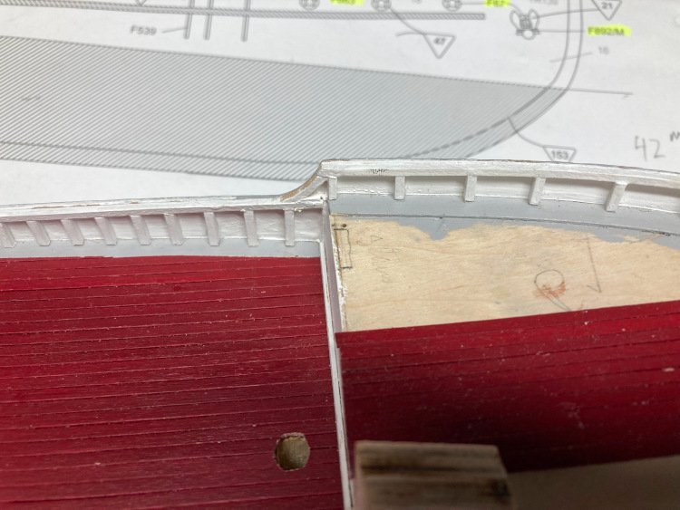
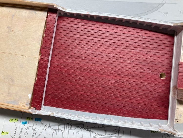
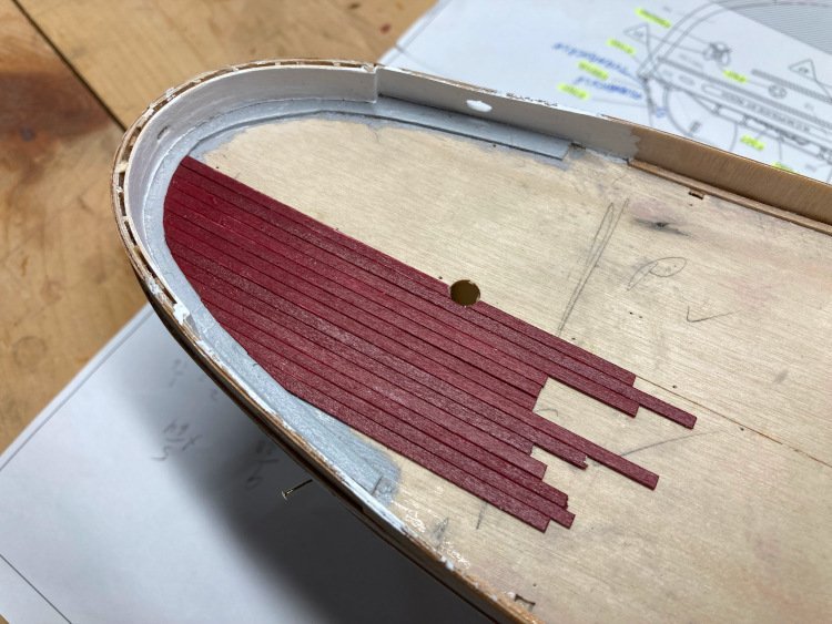
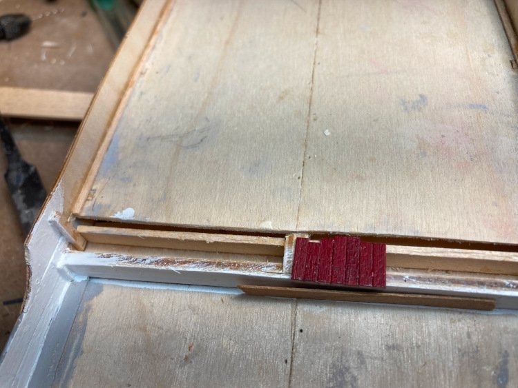
I want to show the ends of the deck planking under the cabin, so I cut the sub deck back a bit and put in a support to carry the ends of the planking stubs. I then filled in the mini planks. This way it won't throw the measurements of the cabin out of whack, as the provided pieces don't account for the extra 1/32" or so that would result if I placed them directly over the sub deck.
So that's it for now. This simple kit is proving to be even more fun that I expected.
Many thanks for checking in. I really appreciate it.
David
- CiscoH, yvesvidal, SiriusVoyager and 1 other
-
4
-
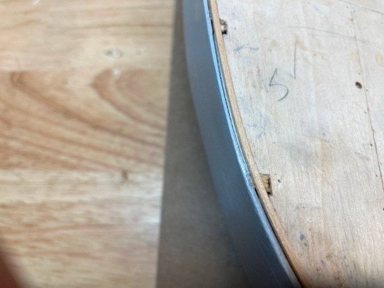
I am torn!
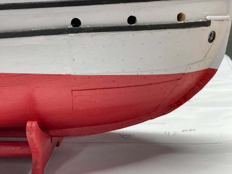
Looking ahead, I discovered this about the portholes in the hull. The rubbing strake runs right over the flanges.
What should I do? If I include that detail then I run the risk of looking like I've made an error, but it appears it would be the most accurate.
Or do I locate the portholes slightly higher to look a little tidier, but sacrifice some accuracy.
Such problems I have!
David
-
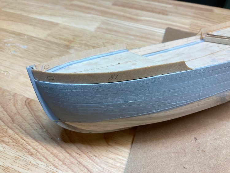
A little progress to report -
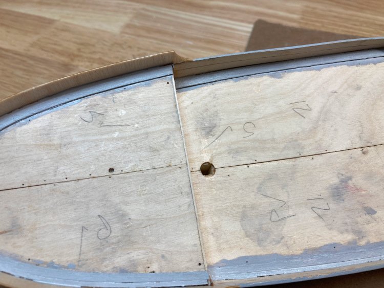
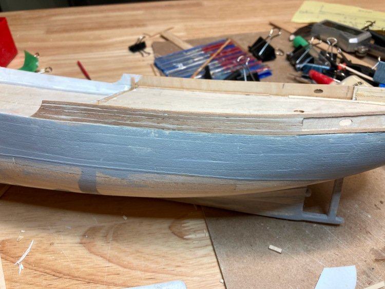
I finished up the planking and painted the gray on the hull.
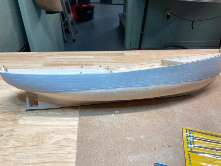
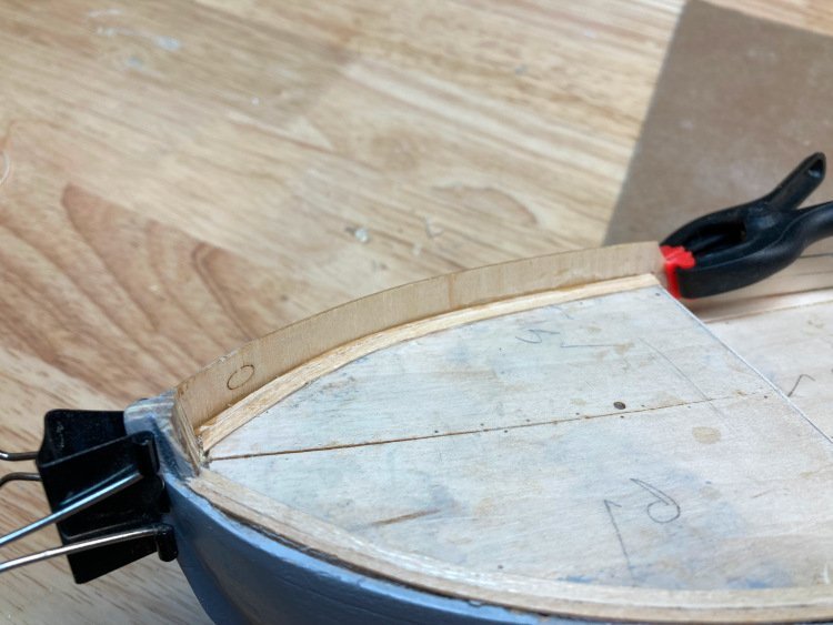
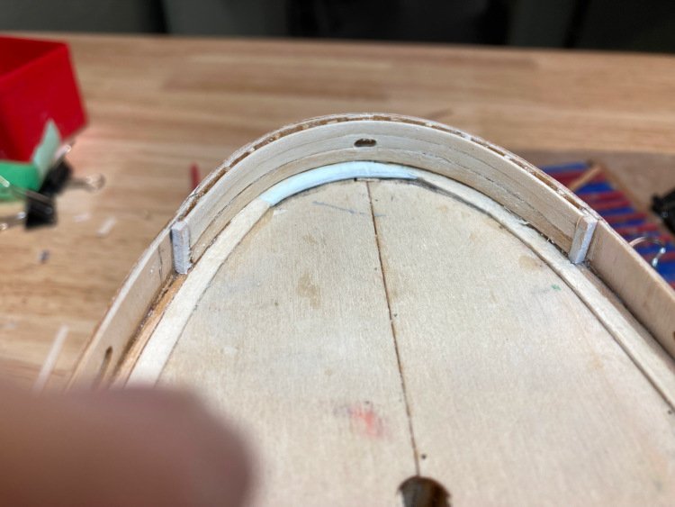
I intend to add all the stanchions to the bulwarks as well as the waterways, both of which are missing from the kit. In order to do that, I broke off (some by accident) all of the bulkhead extensions.
I added the first strip of the waterways (1/32" x 1/16") to the subdeck following its contour. Without the bulkhead extensions, I needed something to place the upper hull pieces against. The waterway created a small lip.
I glued the upper hull pieces in place.
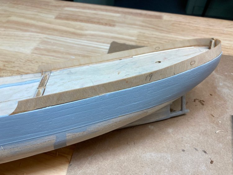
I added the second strip of the the waterways.
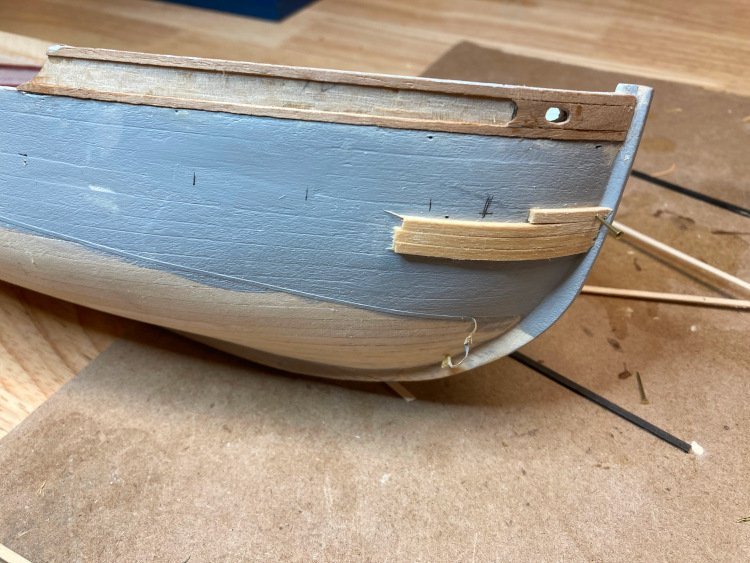
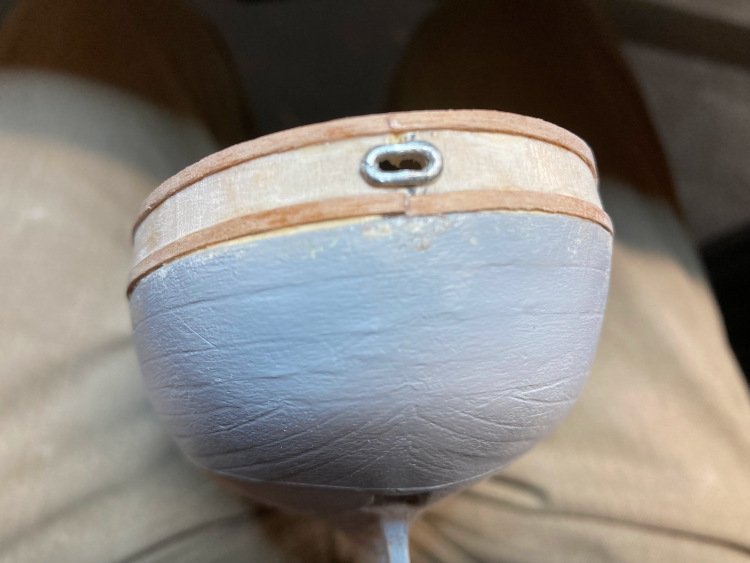
The bulwarks are planked on the inside, just at the stern and bow of the boat. This detail is omitted from the kit, but I wanted to add it. I have the stern done.
There is a hawse opening at the stern of the boat which I wanted to add as well, so I've cut it in, using the hawse trim (from BlueJacket) as a guide. There are none included in the kit, but I'll add them for all five of the hawse openings. The smallest ones from BlueJacket are about the right length, but just a tad too high. A gentle squeeze with a pair of pliers fixed it easily.
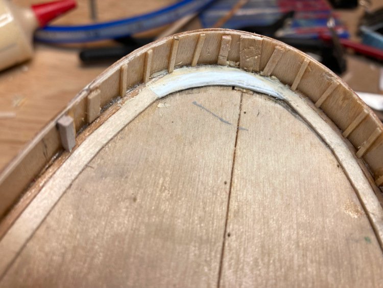
I added the planking to the upper hull at the bow and the stern.
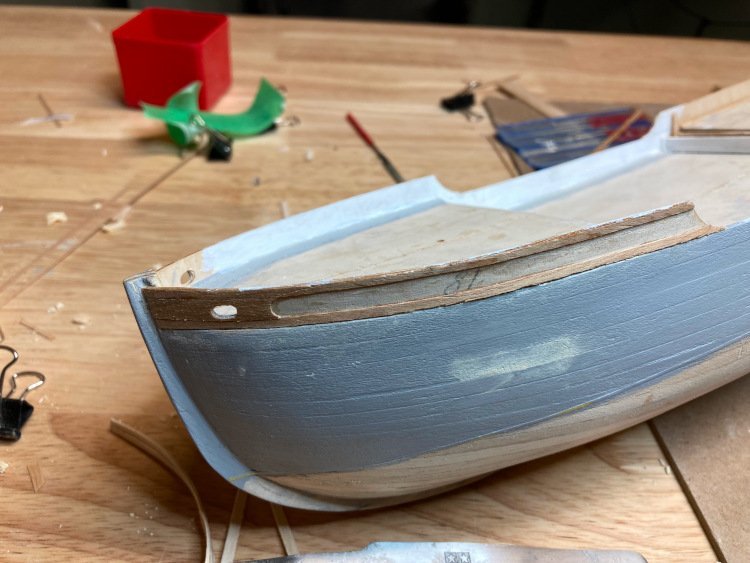
That's everything so far. Please forgive how rough everything looks. I know I still have plenty of sanding and painting ahead of me.
Many thanks for the comments and 'likes.'
David
- James G, king derelict, Knocklouder and 5 others
-
8
-
Your St. Roch is looking very good. I'm curious about one thing though. When you planked the upper hull at the bow, did you check to see if there was room for the decal with the name of the boat to fit in the recessed part. It looks like you've used the 3mm planking, and to my eye, it looks like there is enough room, but when I tried it I could not create a wide enough gap to accommodate the decal. I ended up using 2mm planks.
Looking very nice.
David
-
I've been working on various deck details.
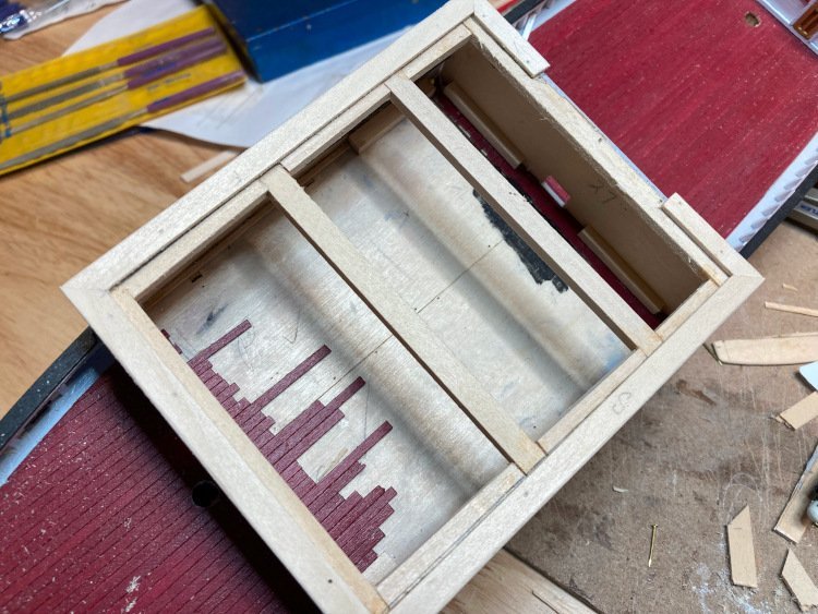
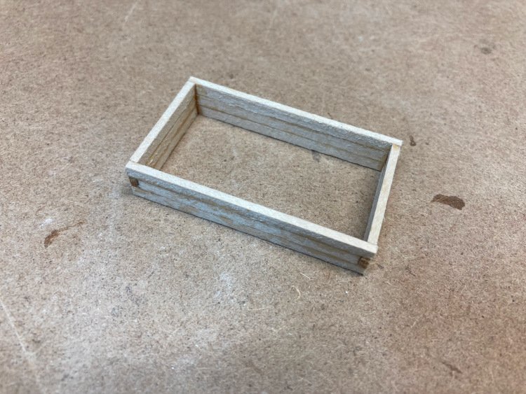
Here's how I built the hatch -
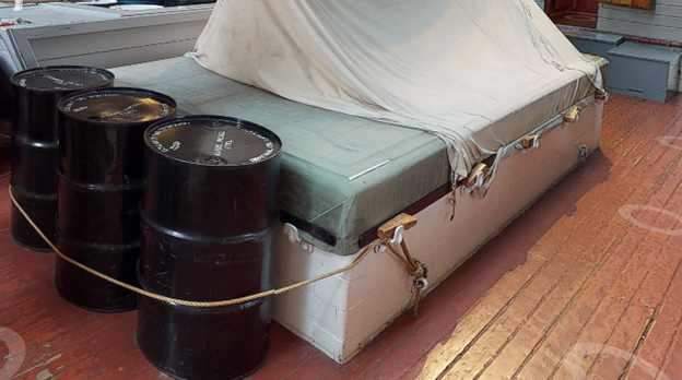
The hatch on the boat as it is at Vancouver Maritime Museum-
The challenge with this kit is determining what size the deck details ought to be. For example, the kit provided hatch is 50 mm long, but on the plan it shows it as 61 mm long. The 360 degree tour that's available online has a measuring tool, which I am finding to be quite accurate. So, the idea is to consider all the different sizes - the kit component, the plans, the 360 degree tour measurement, and the actual model itself. It's a matter of experimenting and determining what will fit and looks about right.
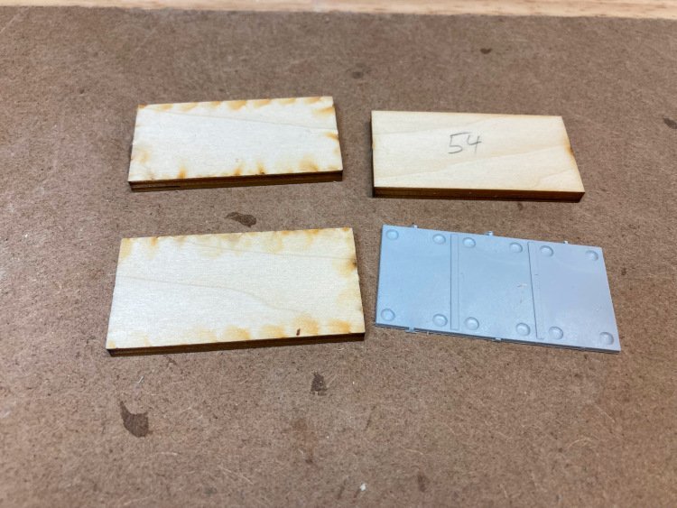
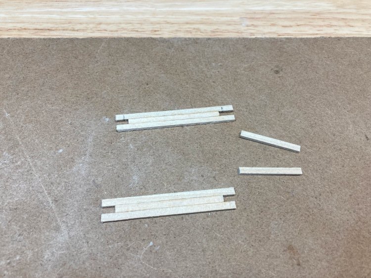
Here's the kit provided hatch -
It's three pieces of pre-cut plywood stacked and finished off with a plastic top. Quite apart from its incorrect length, it's a bit too high as well.
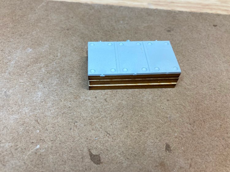
Having determined what size it needed to be. (I can't remember off hand, what those dimensions are) I used 1/16" x 1/8" stock. I built it in the same "finger joint" style of the real one, but that little detail doesn't really show up after it's painted.
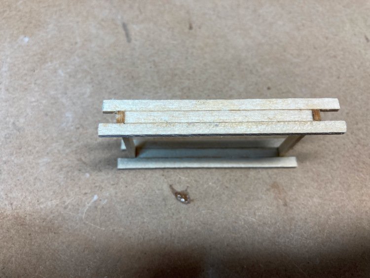
A thin top brought it up to 10.5 mm which is pretty close to the correct height in scale.
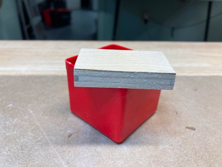
I added a canvas cover using sail material from a previous kit -
Next up is the cargo scow.
Jumping ahead to these details is to give me something to do while coats of filler on the hull dry.
David
- Haliburton, Knocklouder, yvesvidal and 5 others
-
8
-
That's a tricky little bit to build, Steve and you've done a beautiful job.
Chris' comment about MS kits is true and that's why I like them so much. Also those Ben Lankford plans are excellent.
You're going to have a wonderful rendition of the CWM!
David
-
Hi Bill,
To be honest, I had completely missed the tools available on the 360. I expect the measuring tool will be quite helpful. The stanchions are the very first thing I intend to improve upon as well. My plan was to count them on the 360 tour and then eyeball their spacing. But it will be fun to use the measuring tool and see how well they will fit. At a quick look I would say that stock about 3/32" x 3/32" should be about right, but I may have to go to 1/16" square to ensure staying fully within the width of the rail cap its entire length (they can be tricky to install with complete accuracy for their full run.)
I think I mentioned that the measurements on the plans are not reliable. For example, the large chest that sits immediately behind the aft mast is shown as being 1 5/16" long in the elevation view and 1" long in the plan view. That's quite a significant difference. Since I am planning to scratch build all of the deck components it will be necessary to take measurements from the model itself.
As far as my plans for other improvements, my list so far includes:
-the addition of waterways; the kit doesn't include or mention them
-the addition of the six gooseneck vents - along the bulwarks towards the stem
-the other vents are shown to be made out of 1/16" brass rod bent into shape. I've experimented and it bends quite well and will make convincing pipes, but I have some 0.10" x 0.20" styrene strip and I'm going to apply it to create ridges and more closely resemble the real thing.
-there are many items on the deck, most of them appear to be chests. The plans just have you glue pre-cut rectangles together to create boxes. I'm planning to scratch build all the chests with planking and edge trim etc.
-many of the chests on the real boat are covered in canvas; I'm planning to use some of my accumulated sail material to do that too.
-you'll notice in the 360 tour that the deck planking extends slightly beyond the forward wall of the main cabin. The model has the side planking on on the cabin extend right down to the main deck. I'm planning to correct that tiny detail.
-the davits. At first, I thought that the davits were missing from the kit until I realized that the part number referred to the brass rod, which they simply want you to bend into a gentle arc and that's it. Real davits have a bit of a profile; they're not just cylindrical and the same diameter all the way from bottom to top and they need a hole near the top and cleats attached and what not. So I've order some replacement davits.
With respect to the rigging, so far as I can see, it's reasonable accurate. It isn't too hard to follow it on the 360 tour and it differs from the kit very slightly. I am going to upgrade the blocks. The blocks on the real boat are all internally stropped, so I've ordered some from BlueJacket. These are really nice and make quite a big difference. (I used them on my Bluenose.)The kit provides only single blocks, but you actually need a combination of single, double and even triple blocks.
Now the question of the plastic parts. I have to admit that it really annoys me that they use them at all. I would gladly have paid a little more for the kit to have gotten proper fittings. That being said, I haven't quite decided on everything just yet, and I haven't discounted all of the plastic parts.
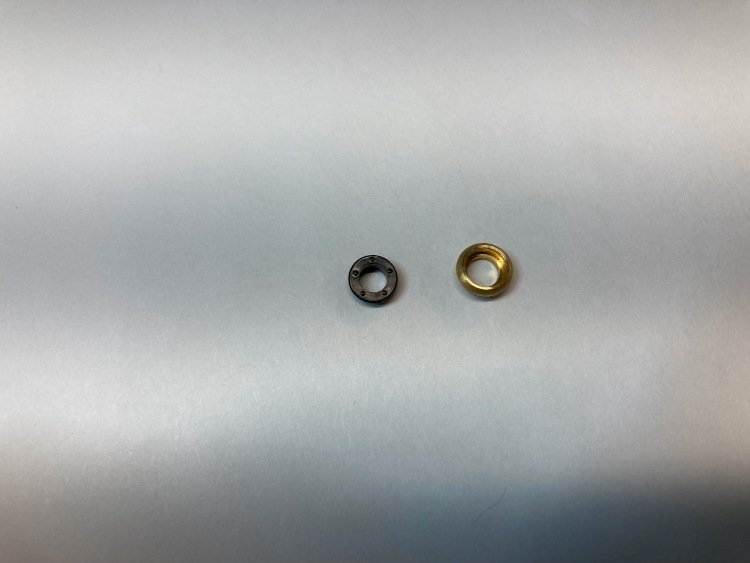
For example, the kit provides black plastic port holes for use on the hull, and quite lovely brass ones for use on the cabin. However, in my opinion, the black plastic ones are actually superior. They have a very flat flange and even the rivets or bolt heads are shown. Since they are to be painted, these ones will very closely resemble the real thing. On the other hand, the brass ones, intended for the cabin, have a very heavy protruding flange and no bolt heads - not like the real ones at all. On the real boat the port holes on the cabin are the same as the ones on the hull - very flat, or maybe even flush flanges with bolt heads and painted. I've actually ordered more of the plastic ones, as I think once painted, they will be the best option, despite being plastic.
I'm planning to use the plastic life boats. They're really pretty bad, but I'm not interested in building wooden ones and to replace them with metal ones isn't that much of an improvement. My compromise is to paint them gray, and make a "canvas" cover out of sail cloth and cover most of them, just like on the real boat. The interiors won't be visible at all and I think I can easily get away with that.
This is not the case for everything. The plastic vents (or stacks) on the other hand are really very bad, so I'm going to replace those with brass tubing. I'm also replacing the plastic propeller.
The big remaining question for me though is the windlass and the two winches. They're quite simplified from the real thing, and are a combination of plastic and brass parts. I haven't had any luck seeing upgrade components online from any of the suppliers that look enough like the real ones. So that leaves either living with the provided ones or building new ones either from scratch or modifying the kit ones. I don't know yet. This is a little way down the line, so I will grapple with that question when I get to it.
Sorry if this seems like a long winded response, Bill, but you did ask!😊 I'm well know for this in the family and can make my wife pass out in seconds when I share this kind of information with her!
David
- CiscoH and king derelict
-
2
-
Jeff, on the website for the Vancouver Maritime Museum (www.vanmaritime.com) there is a very good 360 tour. It shows virtually every aspect of the decks and cabin of the boat in great detail. However, it doesn't show the hull. On Youtube there are various videos that different people have made of their visits to the museum. A number of them include good views of the hull. Together, they cover the whole thing really well.
David
-
I'm back with a build log after a bit of an absence. I've had multiple health problems over the past year, which is in part why I didn't do a build log for my HMS Pegasus and why it took me so long to build it, being away from my shop for long periods of time. However, I seem to be in decent shape for the time being (touch wood) and am back at my workbench.
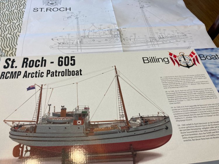
In my hiatus I had been pondering what my next project would be when I stumbled across this model on the Billing website, and after a little bit more research I knew I had found it.
This one appealed to me for several reasons:
-I wanted something simpler than my last few builds had been
-this one has almost no rigging!
-it's a Canadian boat. I haven't seen any other one available as a model, apart from the Bluenose
-it has a remarkable history - it's only the second boat to ever travel through the Northwest Passage and the first to make the trip twice - it's the first do make the voyage in under one year and it's the first to circumnavigate North America - it resides today at the Vancouver Maritime Museum, has been declared a National Historic Site and the great Stan Rogers recorded a song about it.
-there are plenty of pictures and videos online to use as a reference
-did I mention that it has almost no rigging?
When I was in my 20's I built (very badly) a Billing model, but I don't recall if the quality of the kit was good or bad and I had no frame of reference in any case. So this is for all intents and purposes my first Billing kit and I have a mixed reaction to it.
So far the good things are:
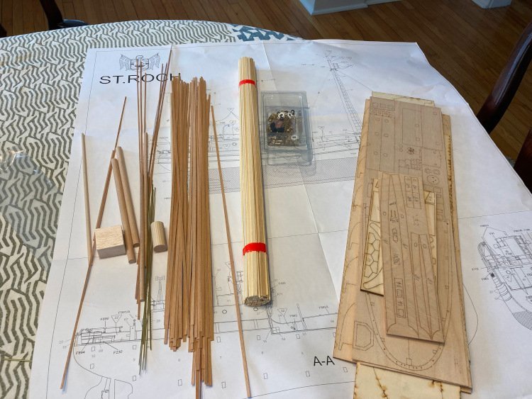
-the laser cutting is very good and the bulkheads and centre keel fit together extremely well. They're as good as I have ever encountered.
-there are quite few specialized brass fittings which are really nice and of good quality.
-while the model is simplified, there are no glaring errors in its representation of the real boat.
However, there are some negatives too:
-there are too many poor quality plastic fittings which come on a sprue just like it was a plastic model car kit.
-the hull and deck planking material is pretty rough and not very consistent in width.
-while I did want a simpler model, there is too much simplification with this one. Built straight out of the box it would look like one of those gift shop ship models. At 1:72 it's large enough for the designer to have incorporated much more detail.
-the plans are poorly drawn. The instruction book is all but useless, which is fine - I didn't expect it to be otherwise, but the plans are disappointing. They appear to be a 1:1 representation of the model, but they are very inaccurate. For example for some of the deck components there are discrepancies in size of up to 1/2" between the elevation and plan views. It's impossible to take measurements from the plan.
Nevertheless, it's going to be lots of fun adding detail and upgrading many of the fittings. I currently have big orders in at BlueJacket and Cornwall.
So far, I have the hull planked, in my usual "suitable for filler and paint" style. I'm a terrible planker, but I never worry about it because filler and paint are my best friends. I've used some planking from my stash, rather than the kit provided planking.
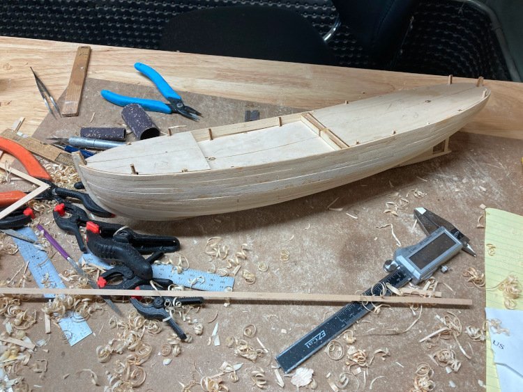
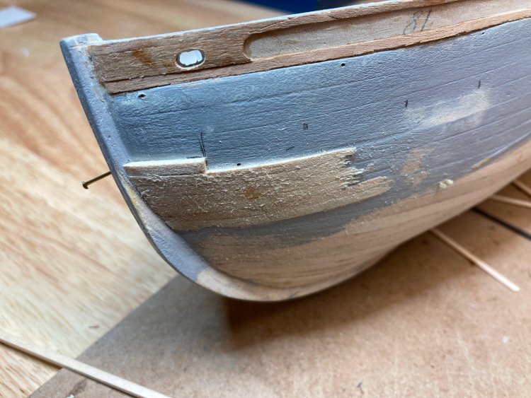
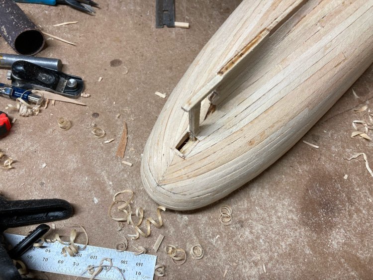
I've made two improvements to the stern area. The kit instructions would have you just cut all of the planking off even at the last bulkhead before the stern. Then you add the two stern blocks and sand them even with the finished planking, leaving them unplanked, just to be painted. I chose to install the stern blocks first and plank over them in the usual way, however I found it to be quite a difficult stern to plank.
Secondly, the kit provides for no opening to accept the rudder; it's meant to just butt up against the bottom of the hull. The real boat has a framed rectangular opening, so I added that detail.
That's where I'm at!
David
- BenD, JacquesCousteau, Knocklouder and 8 others
-
11
-
Hi Tony,
My method is similar to John's but I do it with one seizing. I make a figure-of-eight with the line and do a regular seizing in the centre. I slide the seizing along until one of the loops is just a bit bigger than the block, put the block in and snug the seizing up. Then I draw the second loop until it's just a bit bigger than a drill bit that is the same size as I want the loop to be, put the drill bit in the loop and draw the two ends of the line until everything is snug. A dab of glue, cut the two ends off and it's done.
David

-
-
-
As chairman of our local Habitat for Humanity affiliate (Habitat for Humanity Northumberland) I have been following the development of 3d printed houses with great interest. There are a few Habitat projects in Canada and the US already using this technology.
The current high cost of building is putting a real strain on Habitat's ability to deliver affordable houses. As time moves on, this could become an attractive alternative. Now, if they could just figure out how to 3d print land, we'd be all set!
David
- mtaylor, allanyed and thibaultron
-
3


Mayflower by LCdr Dave - Billing Boats - 1:60
in - Kit build logs for subjects built from 1501 - 1750
Posted
Hi Dave,
I hope you don't mind my chiming in. I honestly just don't get including plastic parts in a wooden kit. It they're going to do that, then why not just make the whole thing out of plastic and be done with it.
My build log probably won't be of too much help, because I built the Model Shipways version, not the Billing version and they seem to differ a fair bit.
There seems to be a problem with the way your grating is sitting on the stem piece. The grating appears to be sitting up against the hull quite well, but by the time you get to the end of the stem piece, the grating is sitting well to the port side. I'm not sure what needs to be adjusted to get the grating centred on top of the stem piece for its entire length, but if you can do that then that should go a long way to getting the side pieces to fit.
If you don't like the plastic side pieces, I don't think it's too big a job to make new ones out of wood. Is there some billet material of the same thickness that's big enough? If so, I would use that; if not, I would just glue up some strip material of the right thickness. Sometimes glued up stripwood will tend to split or come apart, especially if you have to cut close to a seam or against the grain. I sometimes glue the strips to a piece of paper which gives the whole thing a surprising amount of strength. If the piece is to be used in such a way that the paper side won't show, I leave it on. If it's going to show, (as it would in this case) I just sand the paper off after the piece is cut out.You can use the plastic pieces as templates, trace them and cut the new pieces out.
Another big advantage to replacing the parts, besides appearance, is that there is always a lot of flexibility with wood to make minor adjustments to make them fit. (I don't believe I have ever been able to build a truly symmetrical model; fortunately you can only ever see one side at a time, so I don't worry about it.) Plastic doesn't give this kind of flexibility.
Not sure if that's of any help or not, but hopefully it is.
David