
MORE HANDBOOKS ARE ON THEIR WAY! We will let you know when they get here.
×


GuntherMT
-
Posts
2,213 -
Joined
-
Last visited
Reputation Activity
-

 GuntherMT got a reaction from Starboard III in Researching a Constitution Build
Welcome to MSW Fletch. I've only been here since the middle of August, but I couldn't agree more with your comments about build logs. I'm pretty sure I've learned more from the build logs than everything else combined since I started this hobby just over a couple months ago.
I've also learned a great deal by posting my own log, where plenty of amazing people have given me excellent feedback, and also the simple act of taking the pictures, putting what I've done into words, and then looking at what I've done in the photo's (close ups are an unforgiving mistress) has been an awesome learning tool, so I absolutely recommend starting your own log whenever you get started.
-
GuntherMT reacted to grayarea in Armed Virginia Sloop by grayarea - FINISHED - Model Shipways - 1:48 - First Wood Ship Build
Except for a little mopping up, I've finished the first layer of planking. I've been keeping rough track of time spent and I'm at about 75 hours on the build to date. I know that's not fast; not sure if it's slow. But it's the right pace for me.
I've been adding some wood filler to fair the hull - catching some of the places where I had gaps or was a little aggressive in bending planks along the grain, resulting in some laps that needed to be smoothed over.
I've sized the cannon ports but have stopped short of finishing them, since I still have to add layers on both the outside and inside.
Funny to have spent so much time at this point and still have no more than 3 pieces that will actually show in the finished model. But that's also a good thing. Not being an experienced woodworker, I needed the learning curve of the inner layer and now feel better prepared to tackle the hardwood layer. Though I'm sure that too will have its share of blemishes.
I struggled to maintain an authentic planking pattern, and frankly stopped worrying very much about it - except to plan how I'll do better on the outside layer. Since I struggled most with achieving the right curves at the bow, I think my approach will be to plank the bow section first - being most careful to use that as the launching point for an authentic planking pattern. Once established at the bow, I don't think I'll have any trouble maintaining correct distance between places where planks end.
The other thing I'll need to concentrate on is achieving more uniformity in the width of adjacent planks. Again, I think the secret to that, for me, will be getting it right at the bow and letting everything flow back from there.
-
GuntherMT reacted to RevKB in Rattlesnake/Cormorant 1780 by RevKB - Model Shipways - 1/64
Howdy All, I have had a busy few weeks here, Bow Hunting season has rolled around and the Lord has blessed me with two ample does for food this winter. yesterday rifle season opened and our Girls are coming home to hunt so that will be a blast. I have also been crazy busy at the church and working on a repair on a local barn.
Here I am with the corner post and support post in hanging the cross joist.The whole time I was working on it I was imagining working on the ship.
when I have been able to sneak in a few minutes on the old Rattlesnake I have made some good progress. Here are the resent improvements.
Here I soaked down the water boards and held them in place and let them dry, they dried great and held their shape well, making the gluing much easier
Then I measured the gun and ore ports and cut them and glued them on this piece of aluminum.
when they dried I was able to sand and fit them into position.
I also added the extra support to the foredeck for the planking .
As of this posting I have completed all of the gun and ore ports and plan on placing at least 1 gun in the captains quarters and maybe even finishing off the captians area so I can leave the gun ports open to see the detail.
As for the over all flow of the ship I am pretty pleased with the hull thus far.
this is my ships log for week ending Nov 15 2014
In His dust RevKB
-
GuntherMT reacted to ameletters in Unicorn by ameletters - Corel
I got myself now a tough sea-going vessel to start my pirateship - should be called Captain Lubber from now on!
I fought the fear of planking and battled with the rudy rudder for a long time until I won - can tackle everything now!
-
GuntherMT reacted to JSGerson in Rattlesnake by JSGerson - FINISHED - Mamoli - 1:64 - Using Robert Hunt’s practicum
The aft lanyard was installed first. The eyebolt was first glued into place, and then the hook was attached. The loop on the other end now had to be made. I didn’t trust myself to make this loop beforehand and have it fit perfectly. Wrapping the seizing was a bit tricky while holding everything in place but I got it done. The fore lanyards were added in the same manner: one end premade and the other made on the model.
-
GuntherMT reacted to JSGerson in Rattlesnake by JSGerson - FINISHED - Mamoli - 1:64 - Using Robert Hunt’s practicum
With most all the parts made, the boomkins were installed. My model was initially built using Pasi Ahopelto’s model as a guide, specifically for the seats of ease. At the time, I had not seen or at least not recognized what they were on other models, so mine as with Pasi are fairly unique. As a result my boomkins fit snugly against the seats as opposed to looking free standing on other models.
-
GuntherMT reacted to JSGerson in Rattlesnake by JSGerson - FINISHED - Mamoli - 1:64 - Using Robert Hunt’s practicum
In addition to the Fore Tack Blocks, there were two boomkin shrouds per boomkin. Again although not shown in either kit plans, Mr. Antscherl states that the aft shroud is attached to ringbolts by means of a lanyard by thimbles and hooks. The fore ones attached directly to the ringbolts.
The thimbles were made as before, cut from stock tubing; the hooks were bent to shape from leftover brass eyebolt shafts cut off from previous constructions. For the aft lanyard, the thimble and loop were on one end and a simple loop on the other. The fore lanyards would have simple loops on both ends.
-
GuntherMT reacted to Paragraf in HMS Victory by Paragraf – Shipyard – 1:96 - CARD
Today's soap opera episode is about my way of marking planks on the ship's bottom. As the first step, a frame the longest in the circuit (a distance calculated from the lower edge of main wale to the keel) had been divided to 7 equal portions, each of 15 mm width. The last eighth section is about 12 mm width.
Then, using masking tape, I fixed temporarily the battens to the hull. The first batten was fixed 15 mm below main wale, the second 30 mm beneath main wale, the third 45 mm etc. After laying all the battens, I marked them on the hull with a pencil. After that I removed all the battens. This way I got eight long belts. Each of these belts will be first copied on tracin paper, then on the pressboard and finally the pressboard will be cut into single planks.
Now a few words about how I share the long belts into single planks. For this I use the pattern shown below. The vertical line on the right side, shows the maximum width of the plank that is needed.
The first thing is to put the triangular pattern onto the belt, previously drawn on the pressboard, so that the bottom edge of the belt come together the lowest, horizontal line of the triangular pattern. The second step is to move the pattern to the left or right, until the top edge of the belt will cross with the upper diagonal line of the pattern (the contact points are indicated by the arrows). The third is to mark the points in these spots, where diagonal lines crosses with the vertical line. So I follow until the end of belt. At these points where the belt is narrow (for example closer to the bow), the narrower part of the triangular pattern is put on the belt. In this way it is possible to smoothly taper single planks from their largest to the smallest width.
Finally I join the points marked on the pressboard.
To be continued...
-
GuntherMT reacted to Gahm in US Brig Syren by Gahm - Model Shipways
I have started to build the pin rails. In the Syren instructions Chuck mentions that the pin rails should be around 1/32’’ thick, but for stability reasons they are built out of a 1/16’’ thick bass wood strip. As shown in image 1 I used a compromise: I made the pin rails out of pear wood for stability and thinned them down at the (visible) side and front edges to 1/32’’ thickness, however I left the (invisible) rear edges with thickness 1/16’’ so that it was easier to drill holes to pin and glue the rails to the inboard side. As the image also shows I always built the pin rails in pairs by temporarily gluing 2 pieces of pear wood together, drilling the holes for the belaying pins and giving the part its final shape before separating the 2 pieces again. 2 mounted pin rails are shown in image 2.
Image 1
Image 2
I initially used the brass belaying pins included in the kit and blackened them (image 2). However, to my taste their heads are a bit short, so I looked for alternatives – ideally made out of wood. As I did not find any wooden, reasonably shaped, commercially available belaying pins I started to make them myself using my little Proxxon lathe (image 3) and tooth picks. The result is shown in images 4, 5 and 6. On the right side in image 4 you can also see how these wooden belaying pins compare to the brass versions from the kit. Well, I have done 12 so far, so there is still a little way to go to replace them all .
Thomas
Image 3
Image 4
Image 5
Image 6
-
GuntherMT reacted to robnbill in USS Constitution by robnbill (Bill) - FINISHED - Mamoli - 1:93 kit - First Build - Bashed
Today I performed the first rigging tuning. I tensioned up the various lines to align the masts. Once aligned I used half hitches on a number of each set of shrouds to hold the masts I will leave this for a few days to see if anything stretches or needs any tweaking before dressing them all.
Since I had already tensioned and dressed the mizzen futtock shrouds weeks ago, I started installing the ratlines. I plan on installing the futtock shroud ratlines before moving on to the running rigging. I will hold off on the lower ratlines until the majority of the running rigging is in place.
I used David Kump's fantastic Youtube video on how to tie the ratlines as the method I used. The only thing I did differently was I found at least for this set, my bent tweezers were the easiest to use to tie the knots. I found once I got into a rhythm, they moved pretty fast. I am SURE I will tire of making them before all is said and done, but I was pretty happy with the way the first set came out. As I tied them I would lock the end knots with CA once I was sure they were in the correct place and the line was not deforming the shrouds. Once I completed the entire set, I used the CA to set each of the knots.
A link to David's Youtube video is here.
Here is a photo of my first set.
-
GuntherMT reacted to frenchguy in Benjamin W Latham by frenchguy - FINISHED - Model Shipways - 1:48 Scale
Center keel and Keel-Stem assembly
The construction of the center keel is different from I have seen in previous kits. The center keel is made of 2 parts, but each part is made of two similar laser cut pieces, each 1/8 inch thick. So the first task is to glue together each part to form the two half keel parts ¼ inch thick. Needless to say, great care must be taken to ensure that the two pieces are perfectly aligned and flat during the drying process. I used 3/16 pieces of scrapwood (the thickness of the bulkheads) to ensure the slots are aligned perfectly:
Then I let the two parts dry comfortably resting under a gentle 10 lbs of weight.
I then assembled and glued the two halves of the center keel, ensuring the waterline aligns perfectly with the plan. After assembly, I cut the rabbet per the rabbet line using mostly a mini planner.
I then assembled the parts of the keel stem and rudder (also each made of two 1/8 inch laser cut parts) and glued the keel/stem assembly, again using a lot of weight to ensure everything is flat.
Finally I drilled a few holes in the stem and glued-in 1/8 dowels along the stem to ensure integrity of the whole keel and stem.
The instructions says to taper the stem and sternpost before glueing but I prefer to do it after the whole assembly is completed:
Here is a closeup pic of the rabbet and dowel at bulkhead A, also showing the tapering of the stem:
Next, I will start working on shaping the bulkheads for dry fitting before glueing the bulkheads.
Till next time…
Stephan
-
GuntherMT reacted to fmodajr in Wasa by fmodajr - FINISHED - Corel - 1:75
Hello,
I started working on the lower masts.
After cutting them to the correct lengths, I squared up the top ends. Then I extended the sides down, where I will be gluing the housings for the sheaves.
Now, I notched slots for the sheaves on both sides.
Squared up the very top for the caps.
I'm not sure what you call these, but I made the housings for the sheaves to go into. The ones for the lower mainmast and mizzen mast are set at a 15 deg angle and the foremast at 3 deg. (this will set the angle of the lower crosstrees)
Pieces glued to the masts
Foremast notched
The 3 lower masts with the dowels tapered and ready for the sheaves.
Side view of the angles for each mast
Now I will be working on the final sanding and touch-up. Then staining of the masts followed by the installation of the sheaves and woolings (bands) on the masts.
Thanks,
Frank
-
GuntherMT reacted to marsalv in Royal Caroline by marsalv - FINISHED - Panart
Works on bowsprit rigging are cpmpleted now - bobstay shrouds, bowsprit shrouds, boomkin shrouds) and main stay collar.
-
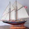
GuntherMT reacted to captgino in Flyer by captgino - FINISHED - Constructo - 1/100 - Pilot boat - first build
it is not glued on yet but I am starting to finalize some details.
-
GuntherMT reacted to Jack Panzeca in Oseberg Viking Ship by Jack P - FINISHED - Billing Boats - 1/25 Scale - 9th Century - (Modified)
Well, she is complete in plenty of time for the Admiral's birthday. The Admiral is happy and as we all know when the Admiral is happy everyone is happy.
The build was 9 months of fun and learning. Completion is very rewarding.
I would like to thank everyone who helped with the build especially Von_Kossa. His log is what inspired me to build the Oseberg in the first place and his research kept me on the right track. Also, thanks to Vivian Galad (we are watching your Oseberg) and all those who followed the build, your encouragement was necessary and wonderful.
I probably would not be involved in this hobby at all without the MSW community. There was not much information out there the first time I tried years ago. Now, whatever you need just ask. Thanks for the help.
Time to move forward. I will now attempt to catch up with Grant and Mobbsie with our first shot at the dark side "Bomb Vessel Granado 1742".
-
GuntherMT reacted to HIPEXEC in USS Constitution by Hipexec - FINISHED - Constructo - 1:82
While I'm making deadeyes, chain plates and siezings....I installed the ship's bell. It's eight bells now, so I have to run.
-
GuntherMT reacted to Chuck Seiler in Continental Gunboat PHILADELPHIA by Chuck Seiler - Model Shipways - 1:24 Scale - Enhanced
Forward platform decking and 12 pounder gun slide.
Dave used Beech to plank his model. Beech is a very good scale oak. PHILADELPHIA was planked in white oak.
Midships gun platform. He doesn't use as many nails per plank per frame here...not sure why.
Note support knees-single bolt through hull and deck (each) with a nail at each end. The bolt through the side will pass thru the hull and be visible on the model exterior. I don't think the model has these, but I am adding them to mine and will discuss it as it arises.
Note thole pins and bits on the cap rail.
Aft cockpit.
Aft platform, starboard arms locker, stern breast hook (not shown on model).
Note square hole under the swivel gun. That was originally where the deck beam for the after platform ran. Arnold intended a mortar to be placed back there. After the mortar exploded during testing, the deck was lowered but the holes remained. The other holes are covered by the arms locker.
Breast Hooks
One breast hook of naturally-curved white oak was placed at each end of the vessel. Both are approximately 5-1/2 inches thick and positioned about half-way up the stem and stempost. The bow breast hook has an arm length of approximately 3 feet, while the opposite member spans a distance of 2 feet. (I think that means the one on the stern.) Forelock bolts were used to secure these timbers to the stem and sternpost and nails were used to fasten them to the ceiling.
The model doesn't appear to have breast hooks. I am still thinking about whether I want to include them or not. Thought?
Exposed floor beams, frames and deck support beams. Rocks were added under the after platform deck to add ballast to compensate for the mortar that was removed. Note: The deck support beams appear to follow side frames/knees rather than the floor beams.
-
GuntherMT reacted to Chuck Seiler in Continental Gunboat PHILADELPHIA by Chuck Seiler - Model Shipways - 1:24 Scale - Enhanced
While I continue with my hull planking, I am going to break from protocol here and post photos of somebody else model. Anguish not. I have asked permission from and received same from both the modeler Dave Yotter and site administrator Chuck Passaro. The primary purpose is to pictorially demonstrate the nail patterns (etc) for PHILLY in conjunction with the narrative from BRATTEN. It also demonstrates some building items from the original plans NOT incorporated into the kit. Finally, it lets you see some really fine craftsmanship up close. My thanks to Dave for these pictures.
A note regarding my discussion of building measures and items from the original plans but NOT from the kit. I realize this is a beginner's level kit and may be the first or second model a reader may be working on. By including the information, I am not inferring that the builder SHOULD include these items, only that they COULD include them, or at the very least know about them.
Organization: Where it makes sense, I will include the information quoted from BRATTEN, followed by the photo(s) that relate to the narrative, followed by my own comments. The BRATTEN narrative will be in one font. My comments, another.
The full text of BRATTEN (with diagrams) can be found at:
http://nautarch.tamu.edu/Theses/pdf-files/Bratten-PhD1997.pdf
Exterior Planking. Philadelphia is planked with five 1-1/2-inch-thick white oak strakes. The lowermost strake is spiked directly to the outside edges of the bottom planking the latter had already been beveled flush with the outer face of the frames. Individual strakes are composed of three to four planks that butt each other on the center of a frame. The planks are fastened to every frame with a minimum of four iron nails. Strake ends were secured in their rabbets with seven or eight nails driven into the stem or stem posts. The edges of the planks were probably beveled to receive caulking material.
Wale. Philadelphia has one rectangular wale 3 inches thick and 4-1/2 inches wide running directly below the sheer strake. On each side of the vessel the reinforcing member is made from two pieces of white oak fastened by a simple flat scarf over a span of four frames. The wale is attached to the vessel with one spike at every frame position. Three iron nails and one spike were used to secure the timber to the stem and stemposts. Hoffman notes that the l-inch-diameter bolts for the midship deck knees also pass through the wales.
Reminder: The top strake is actually two strakes in the kit. Since kit-strake 1 is the same width as the wale, it would probably get 1 nail and the kit-strake 2 would get 3 nails.
Basically 4 nails per plank per frame. Kit only has 16 frames while Philly had 39. I am putting a 'frame' between each of the kit frames except at the cockpits. They will have two extra. This will only give me 34 frames...close enough. It looks like the bottom strake is nailed evenly across the bottom.
Ceiling
Philadelphia has two types of internal planking or ceiling, side ceiling and what Hoffman refers to as flooring. After the keelson was installed. 1-1/2 inch thick ceiling was installed over the rectangular floor timbers in a fore-and aft-direction. Floor ceiling is white oak of varying width (10 to 18 inches). The planks closest to the centerline of the vessel butt against the keelson while the outboard planks are beveled to fit around the frames. The ceiling is attached to each floor timber with two or three iron nails. A well area, approximately 2 feet 5-1/2 inches by 1 foot, 9-1/2 inches was created in the stem (???) by cutting out a rectangular portion of the flooring on each side of floor timber twenty-five. Hoffman suggests that a bailing cover may have been present but was not recovered, presumably floating away when the vessel sank.
Side ceiling was also fashioned from white oak, but 1/4 inch thinner than flooring. Four ceiling strakes of varying width (10 to 12 inches) are present on both sides of the vessel. The uppermost ceiling plank is placed at the same height as the corresponding external plank, effectively covering the frames up to their tops. The lowermost ceiling plank sits directly on the flooring. Side ceiling was secured with three nails at every frame position. The ends of every strake were beveled to butt against the stem and stem posts and are fastened to each post with seven or eight nails in staggered pattern.
Floor and side ceiling plank nailing. Also noted is some deck planking and mast support knees.
-
GuntherMT reacted to Usgecko in USS Constitution by Usgecko - Revell - 1/96 - PLASTIC
Thank you Lukas
Started work on the hull.
Closed off the gun port at the bow (will be modelling the Connie at the time of it's victory over HMS Guerriere, as depicted in the Corne paintings)
Work on thickening the bulwarks, starting first with framing in the gun ports. Next step will be add a layer of plastic on the inside over this framing.
The horizontal lengths of plastic are to provide additional support for placing the gun deck.
Thanks for looking,
Stuart
-
GuntherMT reacted to Paul0367 in HMS Victory by Paul0367 - Constructo - Scale 1:94 - First wooden ship build
I have been busy on the bow decoration and now my ship looks like she wears the Victory's face. I have a nice pile of scale bonfire wood to show for the difficulty though, bending the 2mm x 2mm Ayous is frustrating beyond belief. Soak this wood and it becomes fibrous and stringy, not wet enough it will snap, not wet at all and yes it snaps but also burns on the soldering iron used to bend. For those painting the ship the burns are not an issue but for me, big problem.
-
GuntherMT reacted to giantdog in Swift 1805 by giantdog - Artesania Latina - first build
Thanks guys, just flying by the seat of my pants. Reading and re-reading your logs and copying, so it's all thanks to you.
Not looking too bad so far and pretty happy with the line the planks are taking.
I'm trying to go for no 'drop planks' (is that the right term?) i.e. each plank runs the whole length of the hull.
-
GuntherMT reacted to Tuffarts in USS Constitution by Tuffarts - Mamoli - 1:93 Scale - Cross-section
Just another small update
I decided to dress up the exposed ribs with venere that is cut to imitate the original timbers.
I drew up a plan
And started covering the ribs
And cut the covering from .5 x 5 mm rose wood, I will exaggerate the scarf joints with some pencil lines and I made the odd house shaped timber a darker wood for contrast. I will treenail with lots of small brass wire pieces, but the rest of the model will be treenailed with bamboo.
I still have the keel strip to cover to bring it up to the height of the new wood, these I will do in darker wood if I cannot figure a way to continue end grain.
Thanks for the help with the pumps I think I am going to go with the 'modern' version that came with the kit but I am still going to carry there drain system through to all deck levels.
-
 GuntherMT got a reaction from canoe21 in Emma C Berry by trippwj - Model Shipways - Scale 1:32
Wayne, could you use something like what I did for my top decks? Run a section of planking or if you don't want any curve, use a larger stiff piece, and maybe build up the inside to match the curve, and use rubber bands to hold it down.
Something like this, but with the plank/board run through the frames, under the deck to stick out to either side, and then run the rubber band from one side to the other as needed to keep pressure on. I'll remove the pictures after you've seen them if you'll remind me!
-
GuntherMT reacted to milosmail in US Brig Niagara by Laxet - FINISHED - Model Shipways
Regarding anchor rope; remembering this large diameter rope could well run over 300 feet or more, and when it was not stowed below deck, then it would have been coiled in a figure eight pattern called a flake, and left on the deck near the bow. Flaking minimized the chance of the line fouling when the anchor was dropped.The working end would have to be available at the capstan, as that was used to pull it up. I believe typically when the ship was at sea, the anchor rope was detached and stowed below. It would be brought out only when anchoring seemed to be a probable event.
I would run your rope through the forward grate - even drill or cut out a neat gap for it to fit through. Or flake some on the deck for a satisfactory appearance.
I was told once that the anchor rope for the Victory was run from the hawse below deck to the capstan and back several times, and not flaked due to its large size. Seems to me this would interfere with gun recoil, but maybe there was enough beam.
-
GuntherMT reacted to trippwj in Emma C Berry by trippwj - Model Shipways - Scale 1:32
Good evening, one and all. It has been quite some time since my last update - but here at last is one!
After spending more than a month not even picking up a piece of sandpaper or fitting a plank to the Essex, I have brought the Emma C. Berry back to the build table - being able to actually see the progress on her is quite rewarding.
Have been continuing my work on the interior details. Continued fitting out the cabin, installed the rest of the ceiling on the port side and most of the ceiling on the starboard side as well - leaving a gap for a peep hole from the outside.
My biggest sense of accomplishment, though, is the progress on the wet well. I intend to leave it at this stage - will be painting the interior in a red bottom paint color, but leaving a couple of planks bare to simulate repairs underway. Will also be finishing the bulkhead at the forward end of the cabin (in progress) - that will extend all the way to the deck beams (they are only dry-fitted for now to aid in the wet well construction and cabin bulkhead installation).
The black square will have a sand base inside and then I will be making a small stove for the cabin - that may take a bit of trial and error!
Since I intend to display her as a working vessel undergoing some minor replanking (both deck and hull), I opted for somewhat of a "stained" or "tarnished" look for the ceiling. Will also be distressing some of the other paint as well when the time gets closer.
At any rate, here are the latest set of photos - ENJOY!!!