MORE HANDBOOKS ARE ON THEIR WAY! We will let you know when they get here.
×


Keith_W
-
Posts
1,145 -
Joined
-
Last visited
Content Type
Profiles
Forums
Gallery
Events
Everything posted by Keith_W
-
A bit of Googling did find some plans: http://home.comcast.net/~iver.franzen/Kalnyck.html So you could scratcbuild one if you wanted to. Or you could get someone like rshousha (MSW sponsor) to loft the frames and laser-cut some plywood bulkheads for you. But no kit. If Google doesn't know about it ... then it probably doesn't exist
-
 UV I hope i'm not telling you to suck eggs or anything ... but when I use filler, I apply enough to fill the depression and then immediately use a spare plank to scrape the excess off. This wastes less filler, and makes sanding much easier later.
- 786 replies
-
- 3
-

-
- Royal Louis
- Finished
- (and 1 more)
-
That's OK Greg, I appreciate you taking your time to read the I-I and point it out to me ... but I assure you, I have pored over it in detail so many times that I have almost committed it to memory As Pete himself points out, it is a guide and not an instruction manual. There is nothing about this build that can be considered "definitive" - you can't trust the plans (they disagree with each other at times, like this time!), you can't trust the laser cut pieces (they often disagree with the plans), and the interpretive-info is, as Pete says, his interpretation of how to build it. The only thing I CAN trust is that the metal pieces won't fit if I build it wrong, so that is where I am taking reference from. Even then, you can't hang the metal pieces on a part that does not exist yet In any case, I have fixed it. I decided to correct the angle. I shimmed Part 54 (the upper transom piece) by 2mm at the rear, and shaved off 0.5mm from the front. I now have "almost" the correct angle (off by 0.4°). Measuring from the center of Part 54 to the quarterdeck gives 97mm (should be 98mm according to p.27 / Vol 2 the I-I and the Euromodel plans). I can live with an error of 0.4° and 1mm. The angle is 3.5° off compared to Part 55 below it, but only the most anal of ship modellers will notice. Now that THAT is fixed, I can finally close the book on shaping these transom pieces. Well, not really ... I have to go back downstairs and apply some paint to make that shim invisible
-
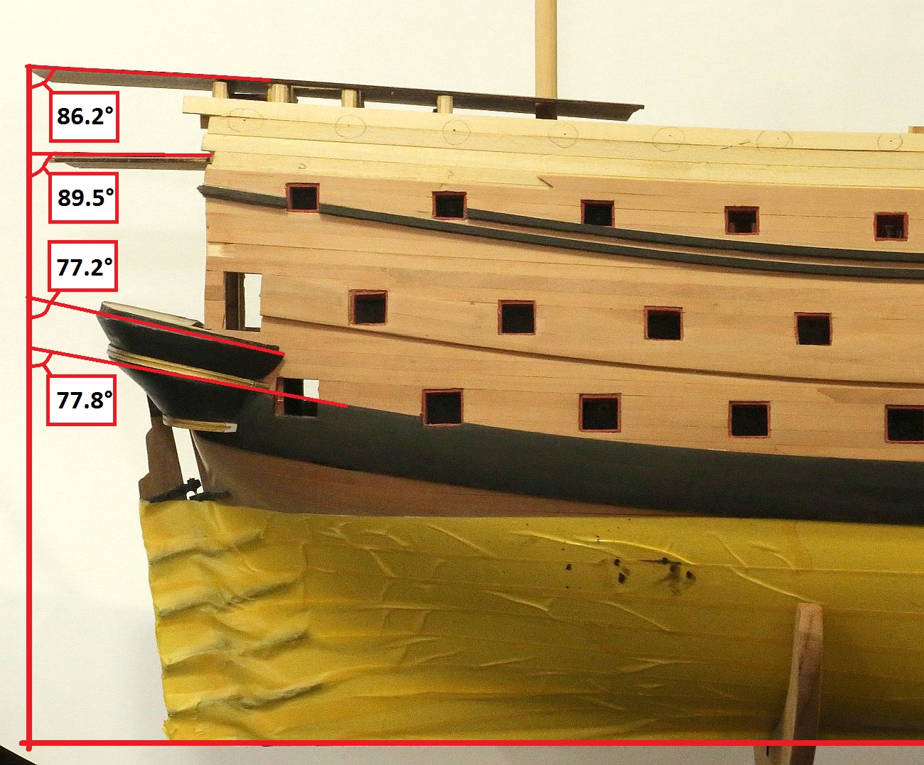
Thanks, Greg. Look at the angle of the quarterdeck in my photo - 89.5deg. This is the true angle of the deck, because I clamped it down before taking the picture. Now look at your first screenshot - "a common mistake is to add the stern decks at right angles to Frame 8". There is no way I am going to incline those transom pieces at the same angle as the quarterdeck In any case, I have decided that I will cut off the quarterdeck when I get to it and reassemble it.
-
Followed you here from your post in "latest profile pic of your build". Decided I just HAVE to see this Hope it's not too late to pull up a chair. I feel your pain, having to square off 66 of those metal gunports. The realization that you have to do something tedious, and do it 66 times over and over again ... is something only a fellow modeller really understands!
- 786 replies
-
- 3
-
-
- Royal Louis
- Finished
- (and 1 more)
-
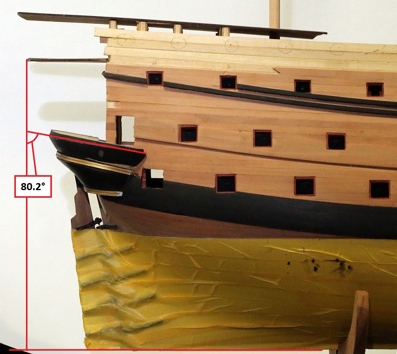
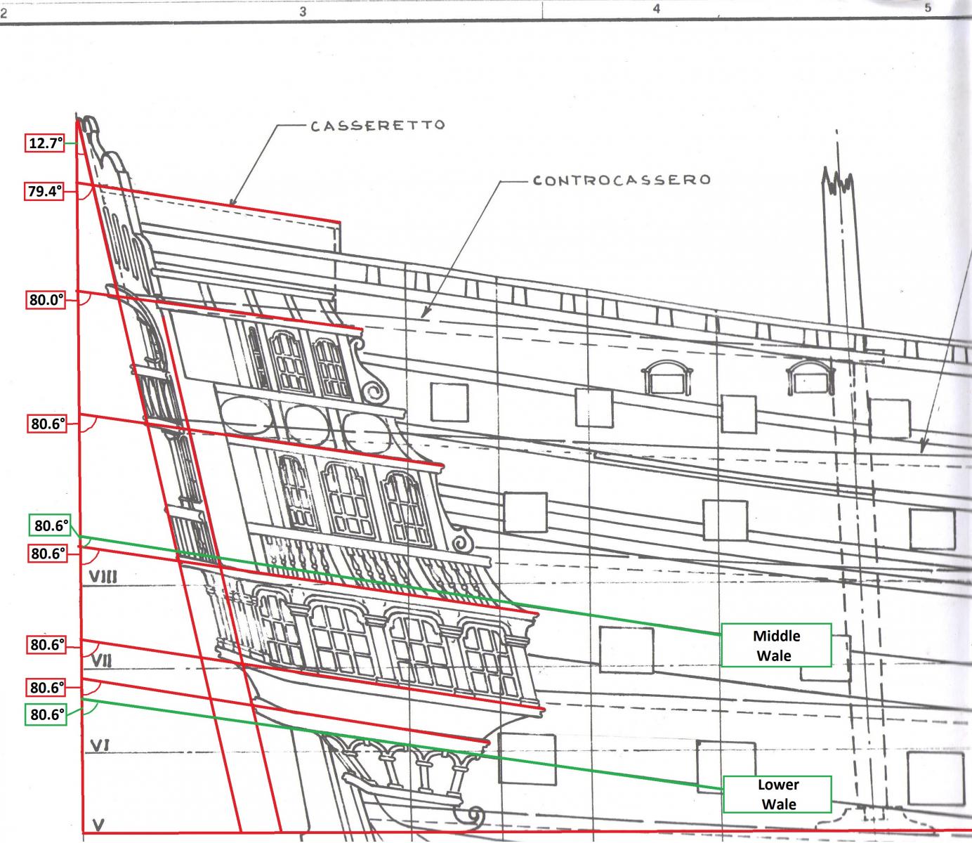
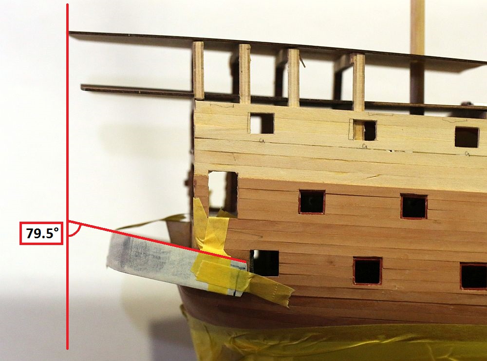
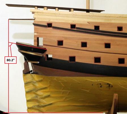
OK, I have checked the angle of the transom support. I mounted my camera as square as I could, then opened up the image in Photoshop, took the horizontal reading from the keel, then measured the various angles. This is an image I posted earlier, where I measured the angles of the various features of the stern. The correct angle for the transom inclination should be 80.6°. This image was taken from an earlier stage of the build, where I marked the angle of the transom support. At the stage I was not far off - 79.5° This image was taken tonight. I measured the angle of transom inclination at 77.2°. I am off by 3.4°! I have calculated that an error of 3.4°, will cause the features of the stern to be shortened by 2.2mm. Now, what do I do ... should I rip off the transom support and start again! That would likely involve destroying Part 54, which I had so meticulously crafted. It is glued on with Titebond, which doesn't really dissolve well in Isopropyl. On the other hand, given that I am scratchbuilding most of the features of the stern, I could simply ... build them different. If I shorten each deck with 0.5mm here, 0.5mm there, it should be pretty much un-noticeable. After all, what's 2.2mm. Decisions, decisions ... By the way, you should note that even with the correct transom inclination, this does not solve the quarterdeck inclination problem.


-
Yes Greg, I have been wondering if I gave the transom a bit too much of an angle, and I checked it against that photo. Trouble is, that photo isn't quite square. There was another photo which I took earlier, from which I made the marking on the transom and the marking was absolutely spot on - see this post: http://modelshipworld.com/index.php/topic/7195-hms-royal-william-by-keithw-euromodel-172/?p=285618I used the marking to locate the position and angle of the transom, checked and rechecked before the glue dried, and the location of the transom piece is faithful to the mark I made. I will probably take another photo, as square as I can make it, to check the angle of the transom piece. I don't really want to imagine getting it wrong, because there is no way to remove the darn thing now without destroying it! It has been solidly glued in place, gaps filled with filler, and nicely faired in!
-
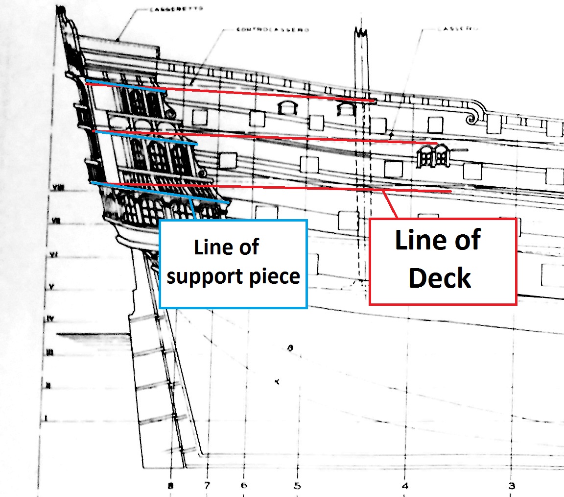
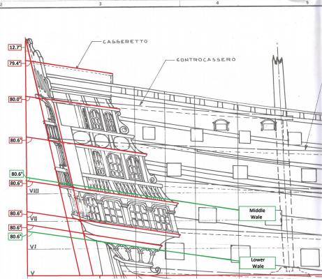
Thanks Greg, I assure you I have thoroughly combed the I-I on the RW and come across both links that you mention. Your first post refers to a set of plans for scratchbuilding the ship. It is true, the balcony should follow the deck. However, if I did so, it would be at the incorrect angle. The stern is meant to follow the line of the wales (see fig. 27 in your second post). Unfortunately, as Euromodel's own plans indicate, the line of the wales, and the line of the deck, are two different things.
-
I am building mine in a different order, so in some areas of the build, you are ahead I decided I would look at the most challenging aspect of the build early, so that I don't set any mistakes "in wood" and then encounter an irreversible problem later!
-
Question on how to curve metal figures?
Keith_W replied to tbrix's topic in Metal Work, Soldering and Metal Fittings
How to make a cast resin mold: http://modelshipworldforum.com/ship-model-casting-and-resin-techniques.php How to bend cast metal strips: http://www.euromodel-ship.com/eng/royal-william-i-i.php#axzz3T1B4ZkLP - Open up "ROYAL W INT 02 V4" - Go to Page 30. This will show you how to bend the metal parts. But really, the method I suggested is the easiest. Just warm it up with your hands and push it over a support. It will bend very easily. -
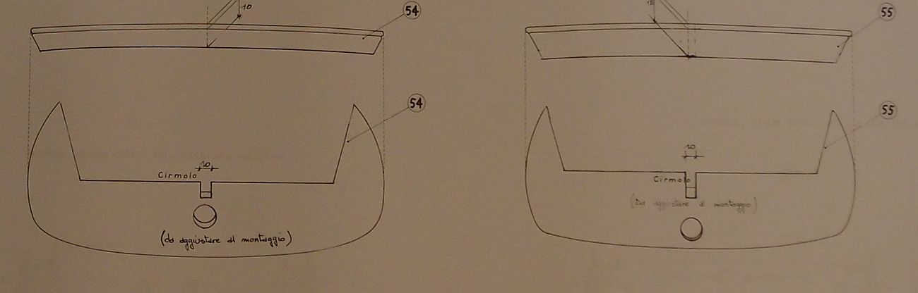
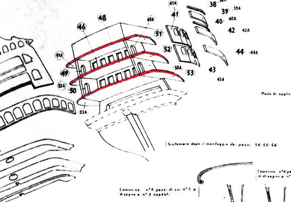
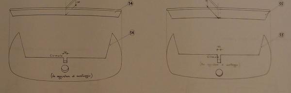
Thank you everyone for your likes and comments. I have encountered another contradiction in the plans. I suspect that nobody out there can help, given that I am the only RW builder so far to have reached this particular stage of construction. Right now I am looking at construction of the stern decks and decorations. This involves fitting a side trim (supplied by Euromodel, Parts 53/53A,52/52A, and 51/51A): Note that the side trim parts are depicted flush with the deck. However, this did not look right to me. The decks do not follow the transom inclination, which means that the side trim parts would be at a different angle to all the features constructed below it. I looked at the other plans, and sure enough: Another plan sheet suggests that the side trim parts are angled differently to the deck, and therefore are NOT flush with the deck. I consulted my usual references to see how others dealt with the problem. Julier does not mention it. As for Pete, on p.34 onwards of his Intepretive Info", he constructs a new deck. Something tells me that I will need to chop off BOTH the quarterdeck and the poop deck, and construct new decks in order to achieve the correct inclination. Perhaps the quarterdeck only. This then raises all sorts of questions as to how I am going to support a deck which is essentially hanging in thin air, and with a whole bunch of heavy metal decorations to be cantilevered off it later. It is very difficult to take measurements off decks which are flexible and hanging free in the air! I will have a think about this, measure a little more, and report back. In the meantime, if other RW builders have taken a look at this, please feel free to say something!

-
Question on how to curve metal figures?
Keith_W replied to tbrix's topic in Metal Work, Soldering and Metal Fittings
tbrix, sounds like you have the Euromodel Friedrich Wilhelm. If it is cast out of the same metal as Royal William (and it probably is), the heat from your fingers should be enough to make it bend. If not, gently warm it over a candle. The metal castings in my kit bend quite easily. To make it conform to the shape that you want, place the casting on it and gently push it into shape with your fingers. -
Thank you Denis and George. Denis, this is the second time I am putting the masking tape on. The first time, I left it on for a few weeks before removing it to install the wales, rudder, etc. There was no problem with removing the tape. This time, I reduced the tack of the tape a little by sticking it on my tablecloth first before applying it to the model. So it should be even safer
-
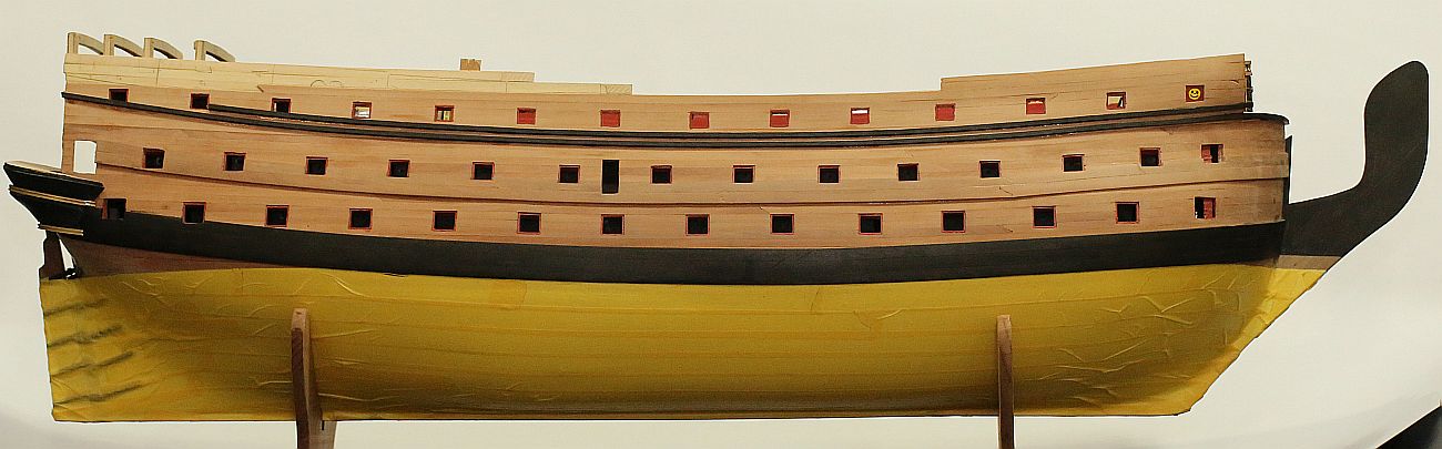
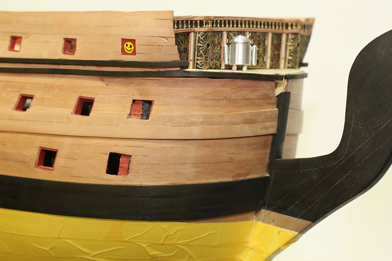
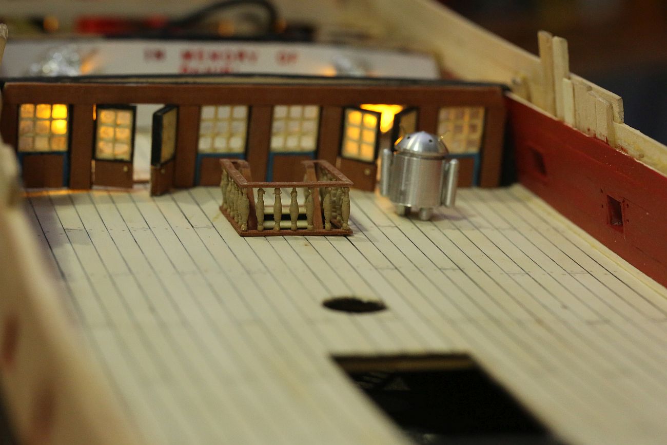
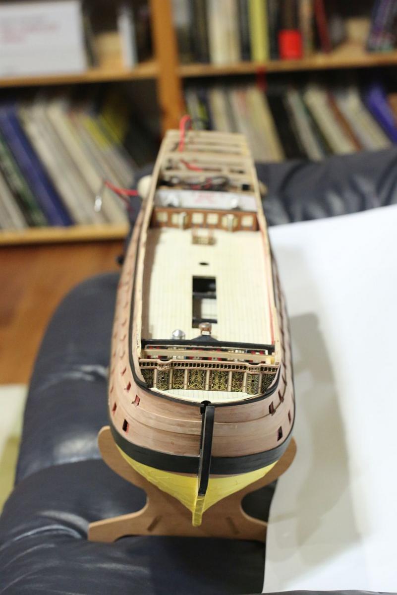
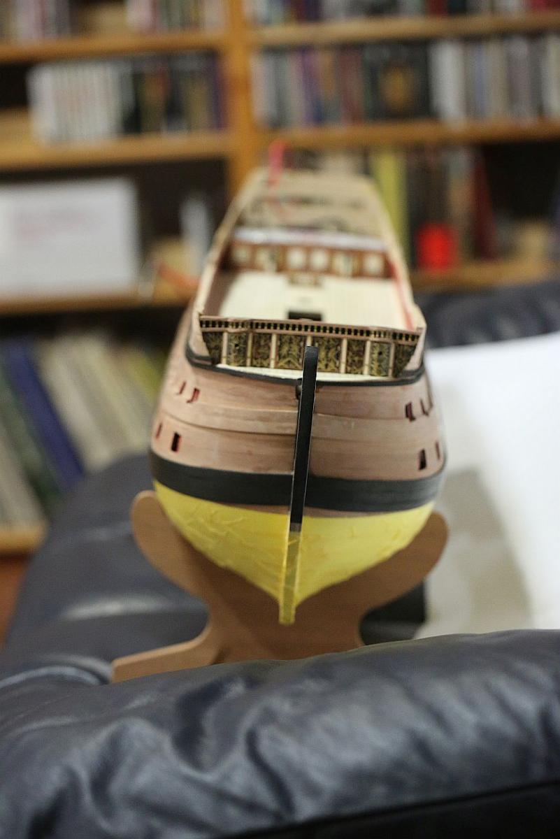
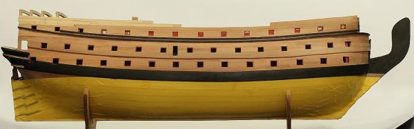
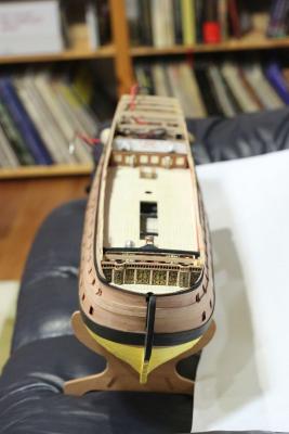
Here are some gratuitous shots of the model, as she is at the moment. The second planking has been carried through to the top. Above this level will be painted black ... and I still have plenty of pear strips left. I think I will save them and revert back to kit supplied second planking material, since it will be hidden under the paint. Other RW builders might notice that ALL the cannon ports (except for the first ones at the bow) are open and can receive cannons! This involved a little bit of engineering to hack away at the bulkheads blocking the cannon openings and finding other ways to reinforce the bulkheads. Because I needed more cannon to fill these open ports, I ordered more from Euromodel. They arrived from Italy in less than a week. Don't worry, that smiley face will be hidden by a gun port. Yet to clean up the bow area. Will leave final sanding till after I install the treenails. Waiting for my laser marker to arrive before doing so. Rear bulkhead and stairwell dry fitted, and illumination tested. View from the front, showing off her lines.


-
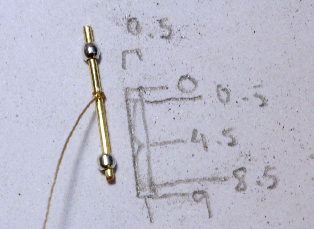
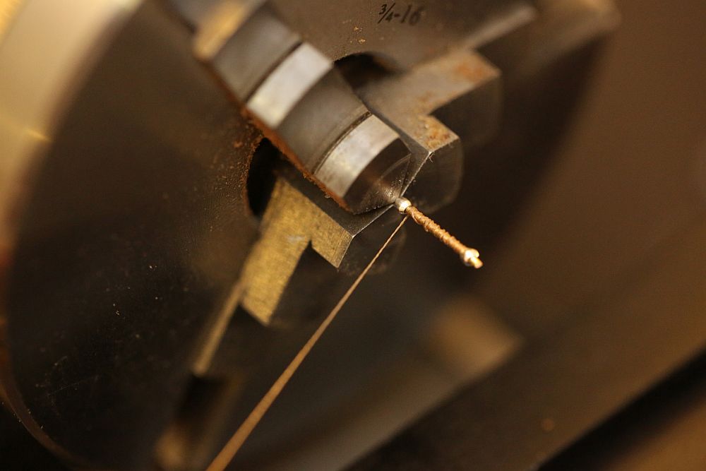
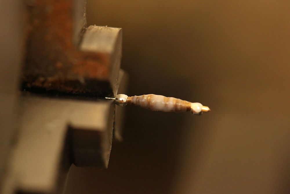
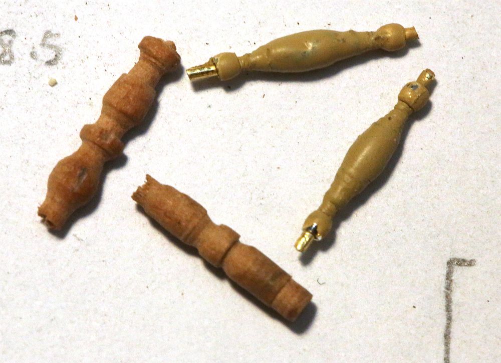
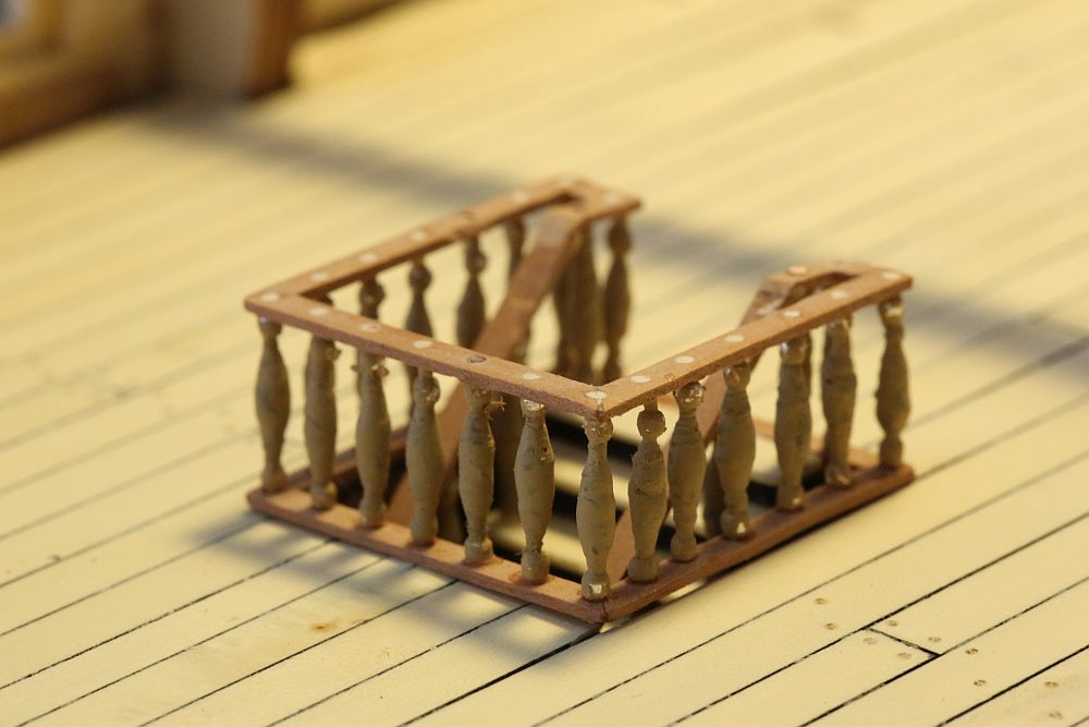
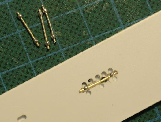
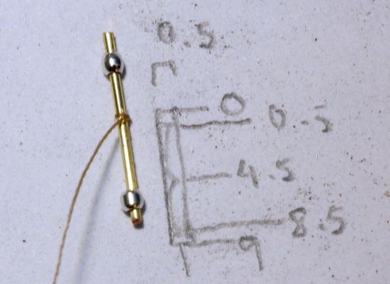
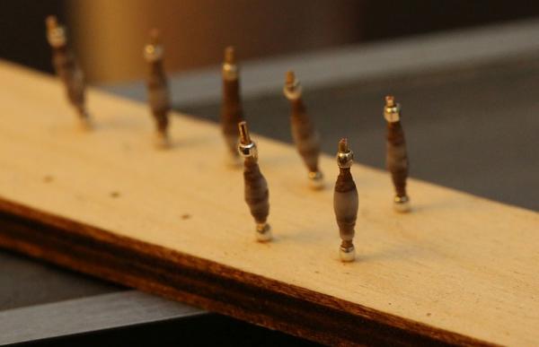
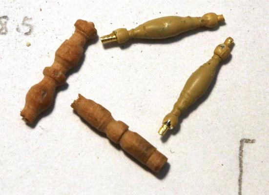
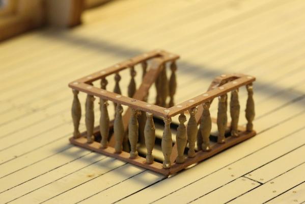
The Captain asked me to make this post, so here it is: how to make balustrades from beads, wire, and string. The beads can be purchased in a jewelry supply shop. For those in Melbourne, and those interested in mail order, this is where I bought it from: (Code 11358), Metal 2.5mm round silver, 200pc/pack, AUD$5.99: http://www.wholesalebeads.com.au/shop.asp?cat=744 (Code 11350) Metal 2.5mm x 2.5mm cube raw, 100pc/pack, AUD$8.99: http://www.wholesalebeads.com.au/shop.asp?cat=1332 Making the balustrade is self explanatory with these pictures. Cut suitable lengths of wire, then CA the beads in position using a suitable jig to achieve even spacing. Tie a string around the middle, then CA it in place. Trim the string flush. Wrap the string around the wire until a bulb is formed. Periodically add a few drops of CA - the idea is to impregnate the thread with CA to make it possible to turn it on a lathe later. When done, coat with liquid Sculpey: http://www.sculpey.com/product/sculpey-translucent-liquid/ Bake the balustrades as per the Sculpey instructions: 130C for 15 minutes. When cool, mount on a lathe and sand off any imperfections. Paint it a colour of your choice. Comparison of balustrades made using this method, and my best effort at turning pear wood on a lathe. Some applications for the balustrades. Mounting the balustrades is dead easy -drill holes through the wood, dip the end of the balustrade in a tiny bit of CA, and push it into the hole. Trim the exposed ends and sand it flat. If you don't like the dots of exposed metal, you can cover it with a thin layer of veneer, or paint over it.


- 396 replies
-
- 14
-
-
- Idea
- Bright Idea
- (and 1 more)
-
Igorsky, it is here: http://modelshipworld.com/index.php/topic/4679-the-kit-bashers-guide-to-the-galaxy/?hl=galaxy
- 425 replies
-
- 4
-
-
- bounty launch
- model shipways
- (and 1 more)
-
Thank you for the suggestion. Perhaps you were referring to Alexey Domanoff's video on how to make scale round headed rivets? Link is here: http://modelshipworld.com/index.php?/topic/3315-making-small-nails-with-round-head/?p=91910 Also, if you want to make hexagonal bolts or nuts, you might want to look at "The Nutter": http://scaleplasticandrail.com/kaboom/index.php/all-other-subjects/all-things-tools/75-all-other-tools/399-the-nutter-scale-detailing-tool-by-the-small-shop
-
My usual method: - lightly sand with 400 grit paper - light coat of primer (either use Tamiya spray metal primer, or Admiralty paint on metal primer) - paint with colour of your choice.
-
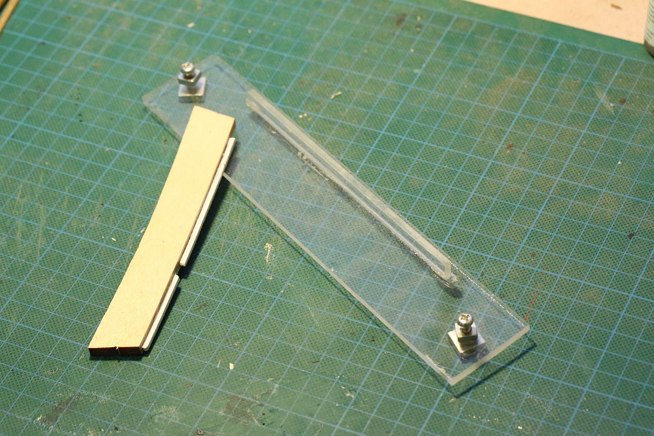
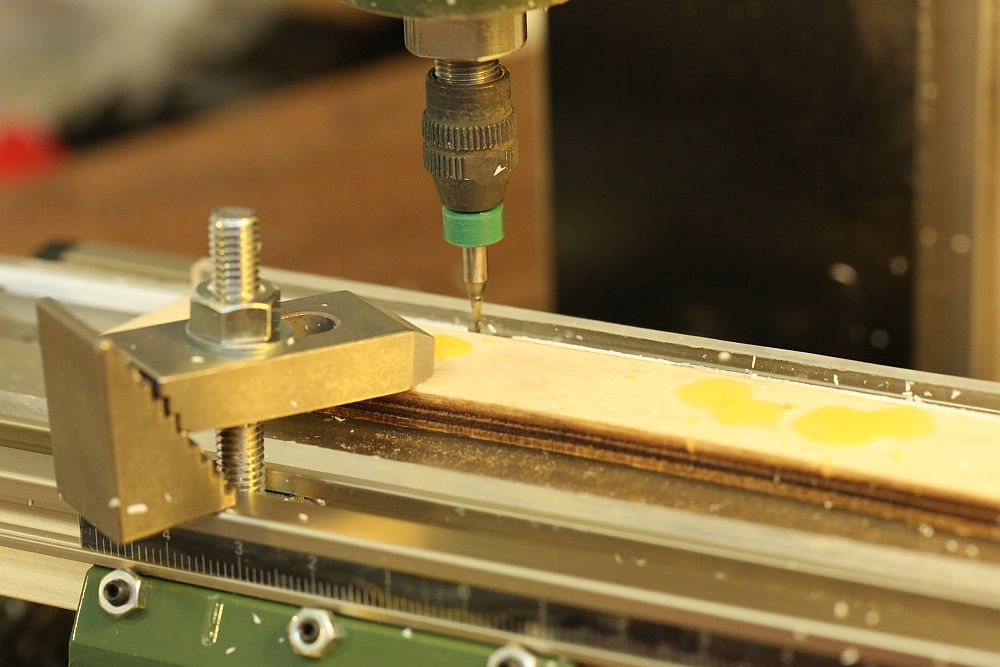
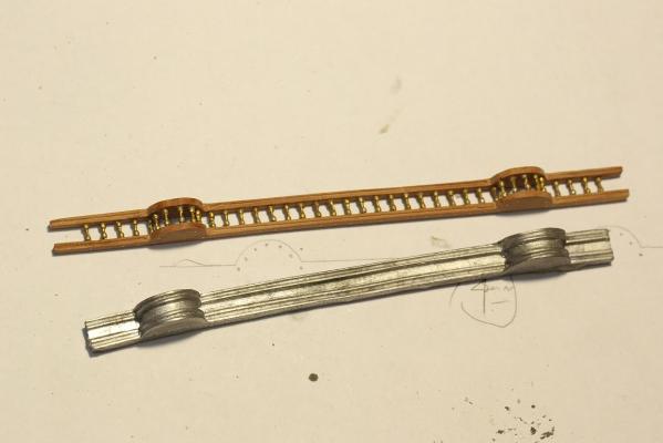
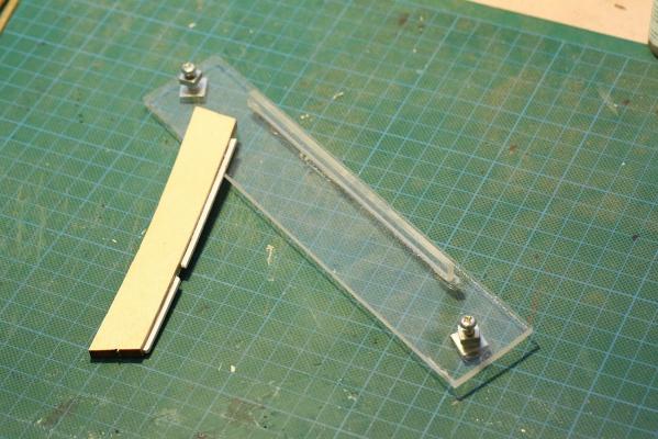
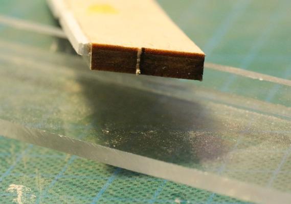
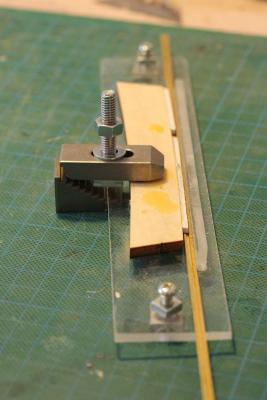
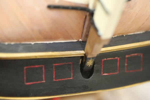
I thought that MSW'ers might be interested in how I fabricated the replacements for metal pieces 11241 etc from scratch. These metal pieces are meant to be decorative strips on the edges of transom pieces 54 and 55. I decided to engrave a profile on a 3mm x 2mm styrene strip, using my Proxxon MF70 milling machine. But, how do you hold down a thin, long piece like that on a milling machine? The answer is to fabricate your own hold-down piece. On the right is a piece of acrylic. Two holes were drilled on either end. It does not matter that they are not square to the piece. The acrylic piece was then mounted on the machine, using screws in the two holes to mount the piece to the table. Now a 3mm wide and 1mm deep slot was machined into the acrylic piece. A thin piece of acrylic was glued into this slot to act as a fence. Given that the machine itself milled the slot, the fence was guaranteed to be square. The piece on the left had a thin strip of styrene glued on it. You can see from the first picture that there is a slight gap in the styrene. This is where the milling head goes through. This acts as something like a "fingerboard". This is the complete setup, complete with hold down step clamp to keep the fingerboard in place. A completed styrene strip with a channel milled in it is also shown. The setup at work. And finally, the completed transom piece 55 mounted on the ship, with the decorative pieces attached. Note that I have also fitted the lower mahogany piece 56 as well. I didn't do quite a good job as I would have liked shaping it, but a tiny bit of filler and paint takes care of it. Not that anybody is going to look under the ship and up at the transom piece, but at least I know that it has been neatly closed over! I have also painted a little decorative motif on the rudder, and follow the black line through from the wales, to the transom, and on to the rudder. I saw it on the USNA RW. The gunports have been simulated by carving a square outline and painting it red.

-
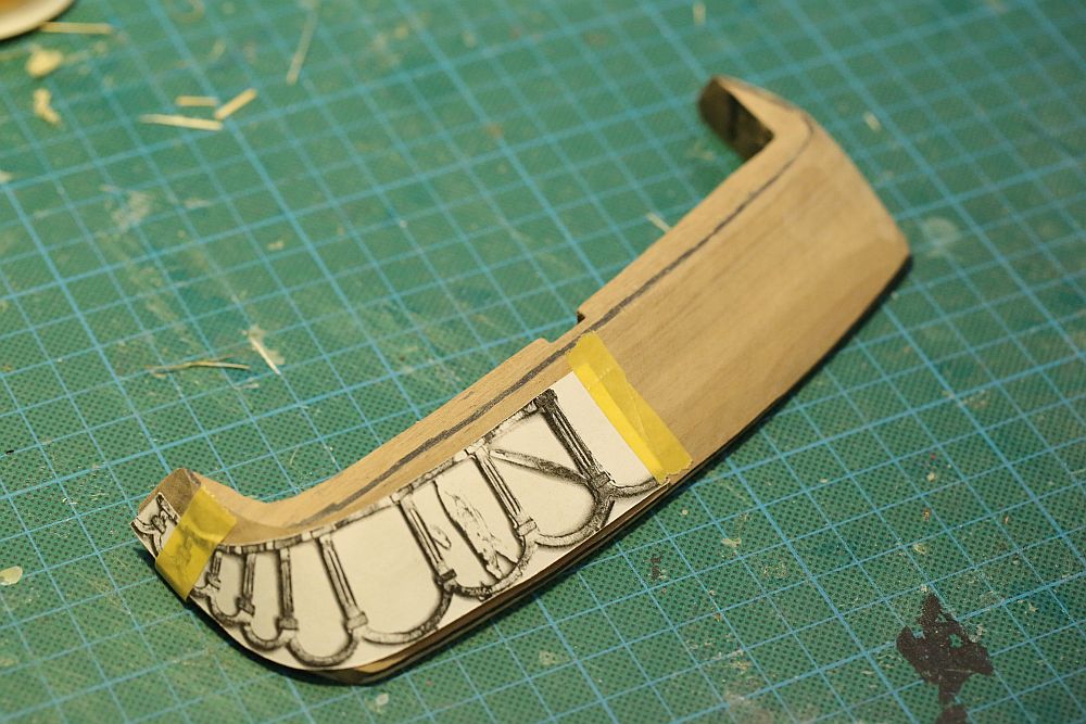
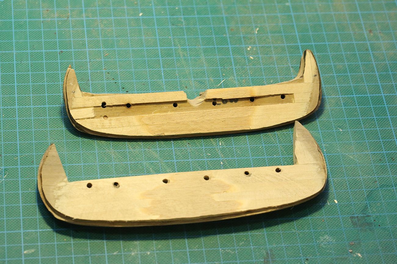
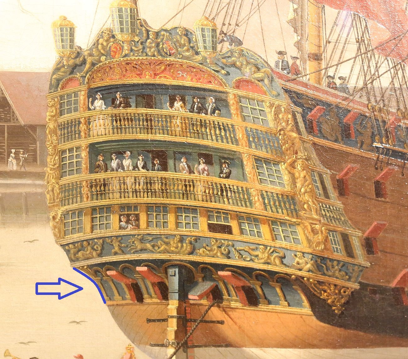
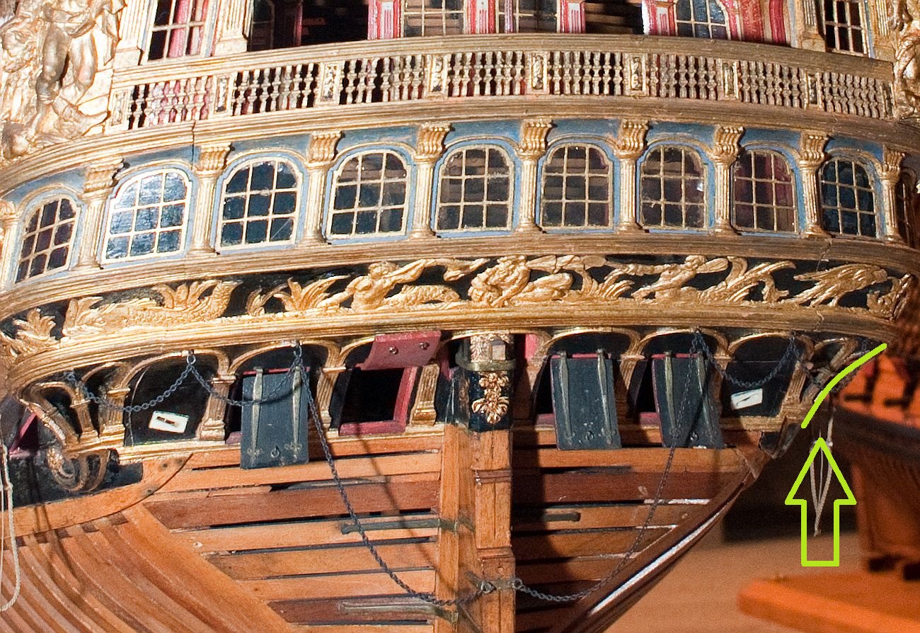
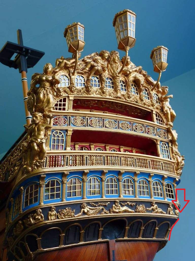
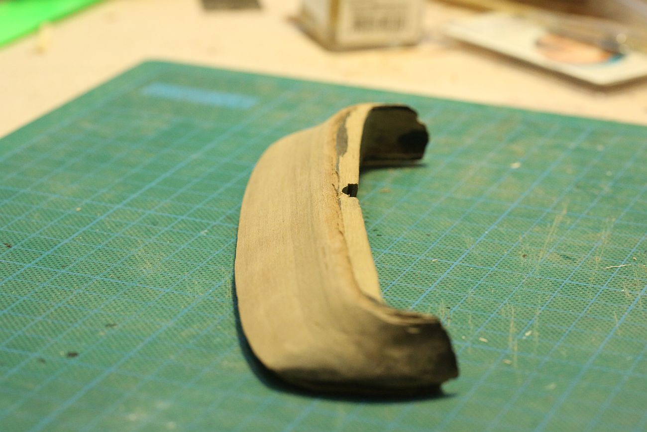
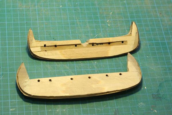
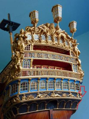
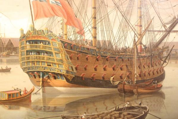
Thanks Greg, to be honest I am not very happy with it. I can see the brush marks on the front bulkhead, and IMO that's not good enough. I have been thinking of doing it again, but I have been practicing my painting and I can't seem to get good enough such that brush marks are not visible. I may have to live with it. A few more words about those infernal transom pieces, 54 and 55. I have FINALLY completed them and mounted the lower transom piece on the ship. If you recall, this was what it last looked like when I showed the piece on MSW. I was pretty happy with it, until I realized a few things. Firstly, the plans called for the pieces to be bent with a 2mm deflection from the center to the sides. I soaked the pieces in ammonia for 12 hours, then boiled it. No luck. I soaked it again for 48 hours, then boiled it, then mounted it on my vise. Still no luck! I mounted it on an appropriately curved piece, then drove my car over it*. Still nothing! (* The reason I am so brave with my abuse of this piece is because I know that it is relatively easy to fabricate a new piece from scratch) In the end, I decided to shim it and then shape it on the disc sanderso that it attained the correct cross section when viewed from the rear. The holes that you can see are mounting holes for dowels, to hold both pieces together to check for alignment and shape. I FINALLY managed to get the correct profile. The next thing I noticed was this: (From top to bottom: John Clevely's painting of the Royal George in the NMM; Royal William model in the USNA; Victor Yankovitch's model of the Royal William) The arrows indicate that the lower transom piece has a distinct concave profile. Note that this is not indicated in Euromodel's plans, nor does Pete's I-I take note of it. Glad that I realized this before mounting it on the ship, I gave the lower transom piece a distinct concave profile. It looks more graceful now, I think.


-
Matt, I know it is off topic but I would love to see your 24" by 24" crochet work. My jaw dropped when you first posted a picture of your netting some days back. Not only is it beautiful work, but it looks so RIGHT on your boat. It is functional and totally looks as if Bligh would have had to use something like that to keep his extra provisions.
- 425 replies
-
- 5
-
-
- bounty launch
- model shipways
- (and 1 more)
-
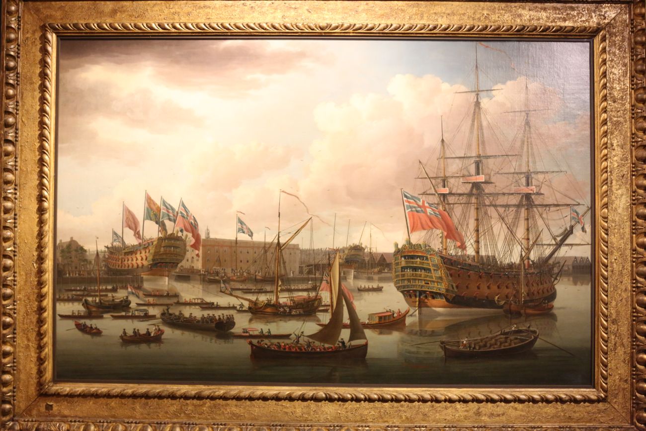
Hi Vince, this is a painting of the Royal George in 1755, by John Clevely the elder. I took these photos when I was in the NMM in Greenwich last year. You can clearly see that the white hull follows the waterline, as per Euromodel's plans. The RW model in the NMM and the USNA do not have white painted hulls. Of course, that is the Royal George and not the Royal William, but I would imagine that she would have been painted in a similar way.

- 593 replies
-
- 3
-
-
- royal william
- euromodels
- (and 1 more)
-
Congratulations on finishing your boat! She's a beauty! That paddle steamer looks like an interesting subject. But ... a 3 decker does not strike your fancy?
- 83 replies
-
- 1
-
-
- bounty launch
- model shipways
- (and 1 more)
-
Thanks for your likes and comments, Steve, Vince, Brian, and Gunther. Steve, I might point out that there is hardly a "crowd" of RW builders, only four of us building from the kit and another 2 scratch builders who are both doing a far better job than I could ever dream of doing. Gunther, the reason I say not to use Titebond is because it doesn't dissolve so readily in water. There is something about the formulation of Titebond that makes it cure faster, cure stronger, and is more water resistant than normal PVA. All of these are desirable qualities, but not when you want to make a temporary bond!