MORE HANDBOOKS ARE ON THEIR WAY! We will let you know when they get here.
×


Keith_W
-
Posts
1,145 -
Joined
-
Last visited
Content Type
Profiles
Forums
Gallery
Events
Everything posted by Keith_W
-
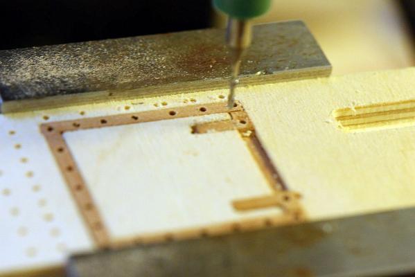
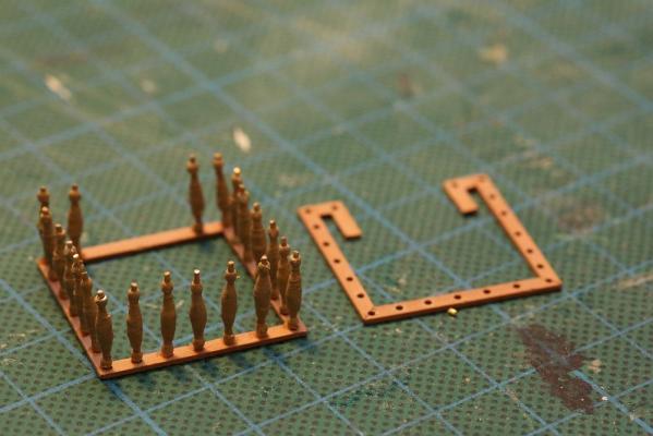
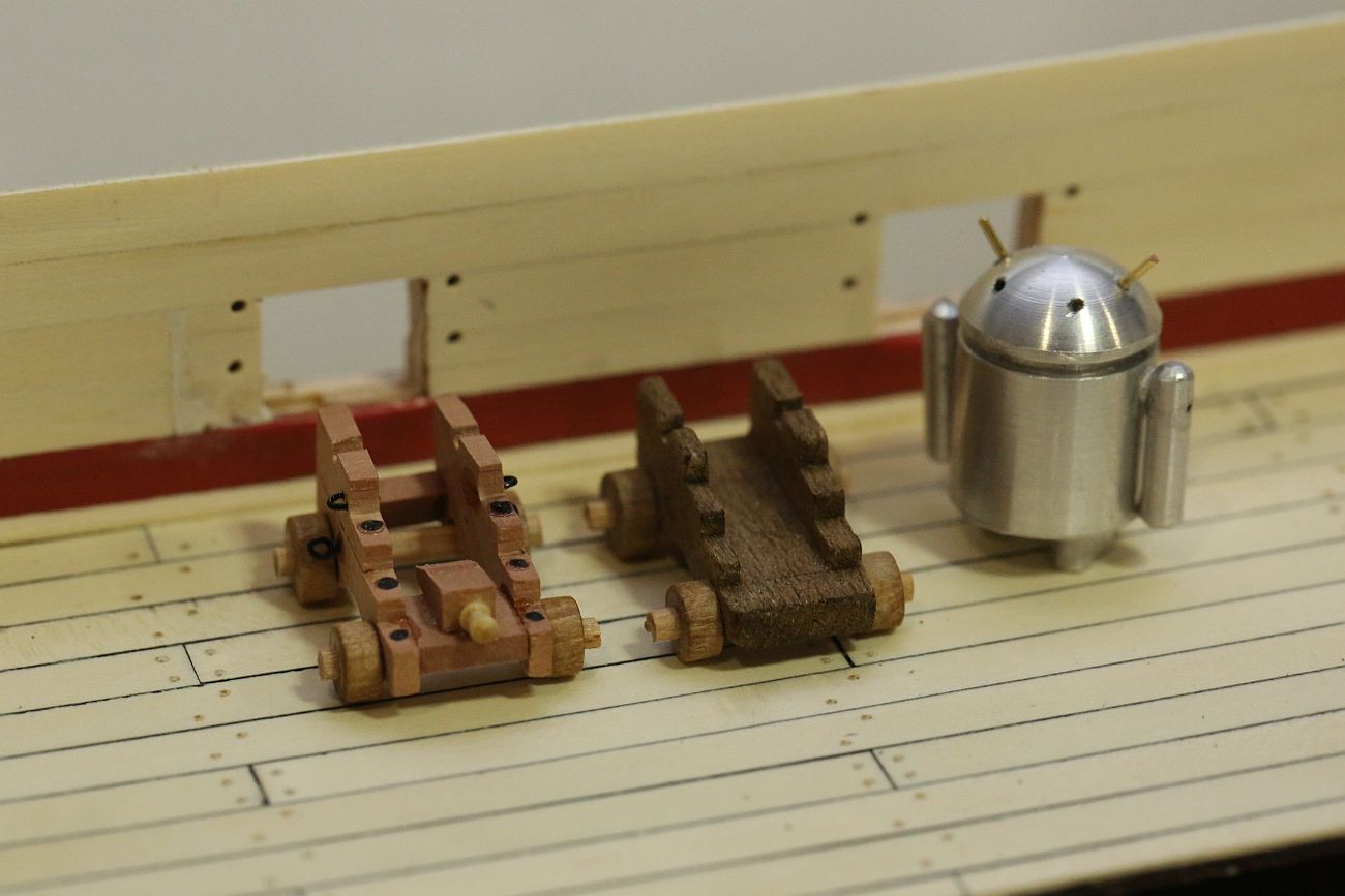
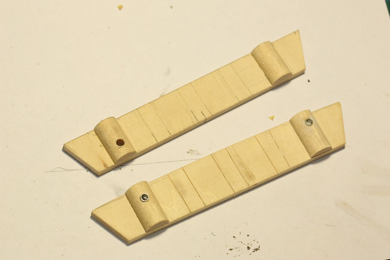
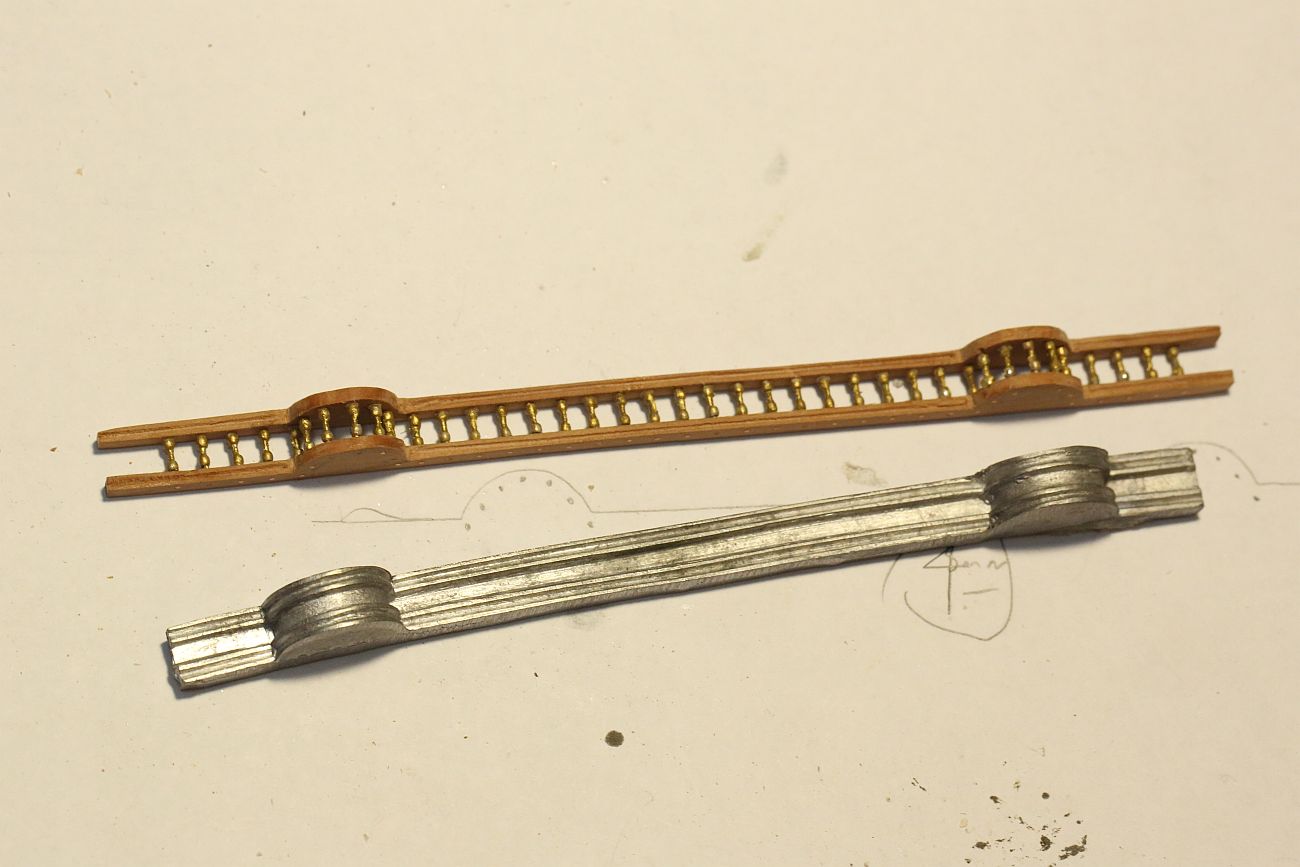
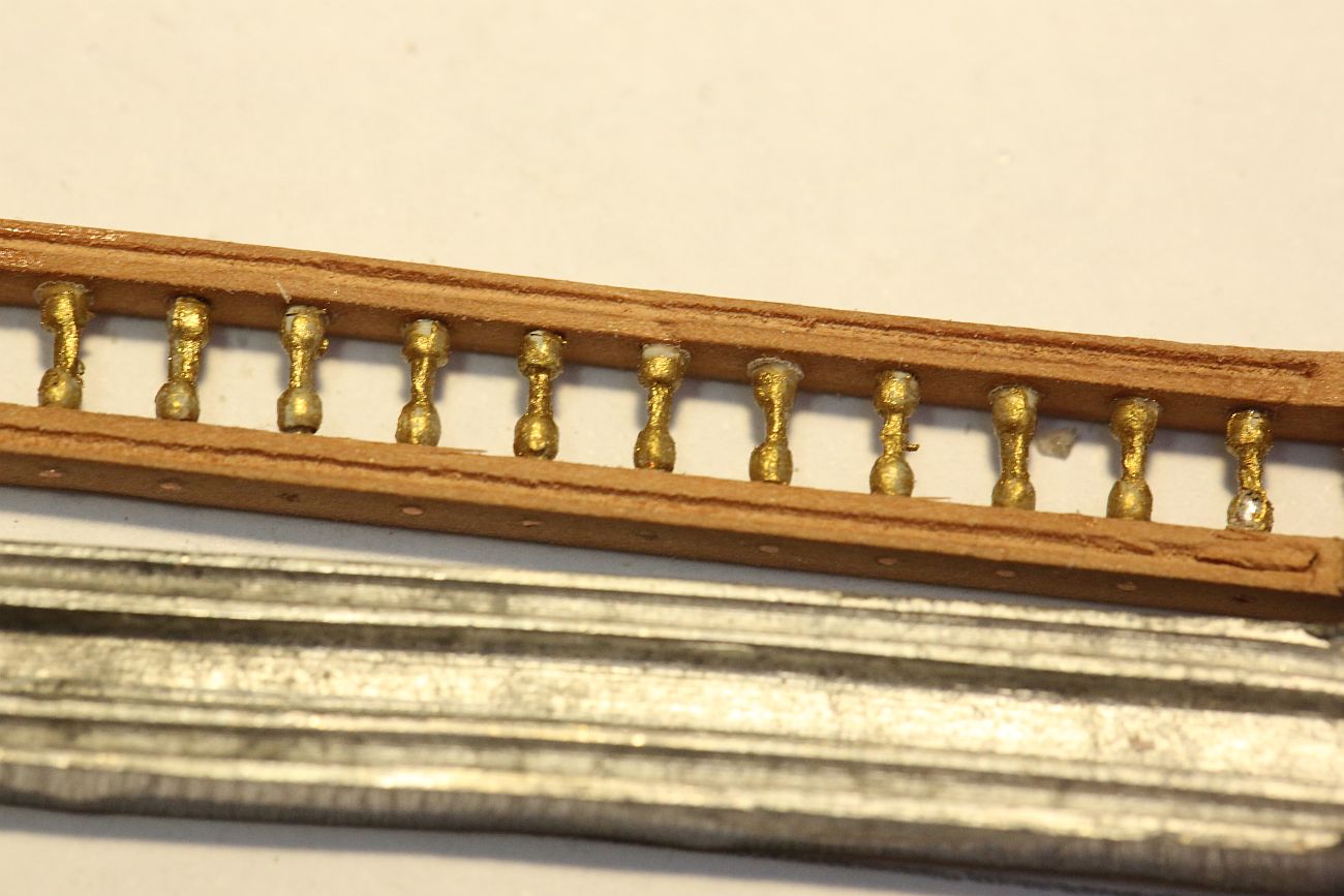
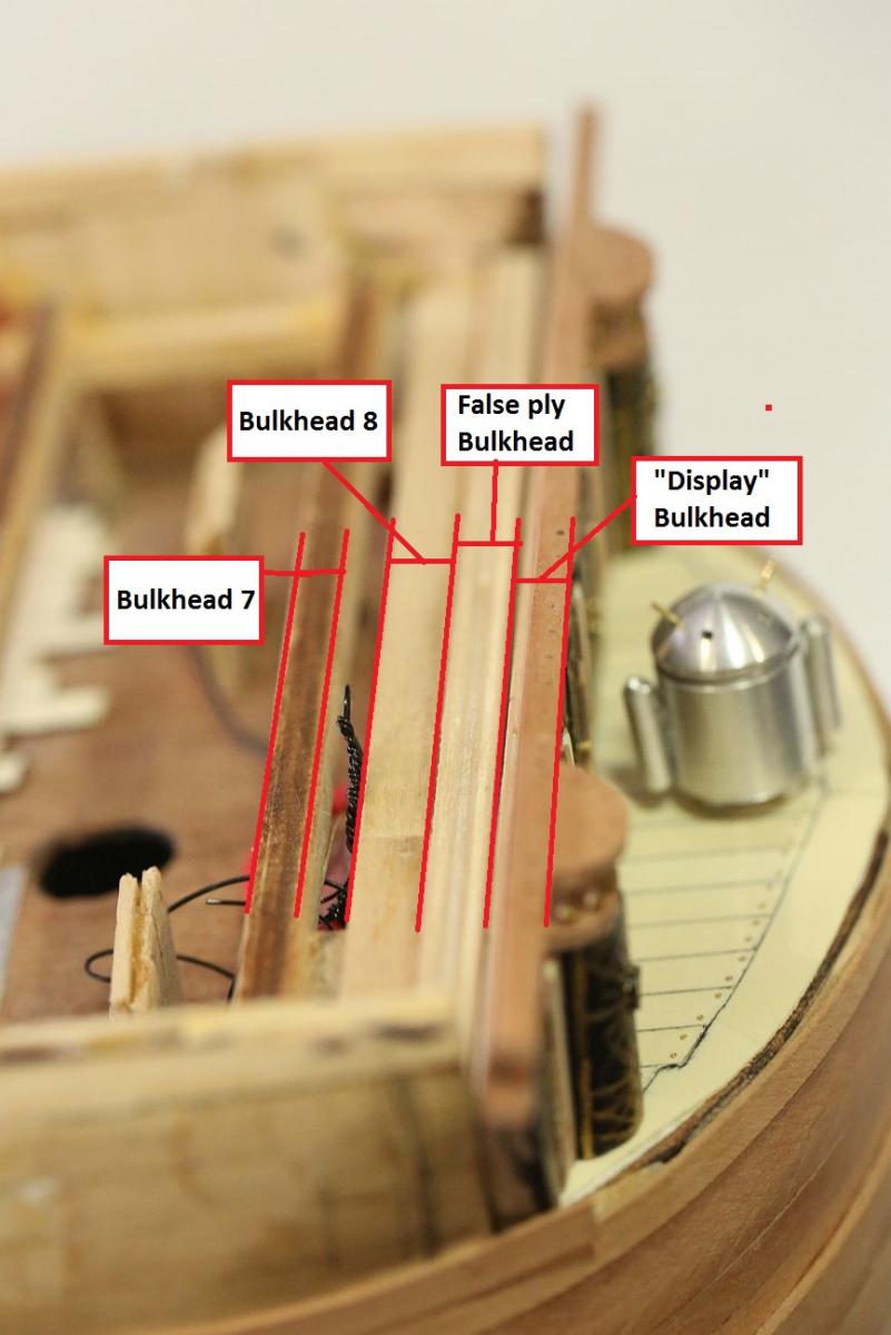
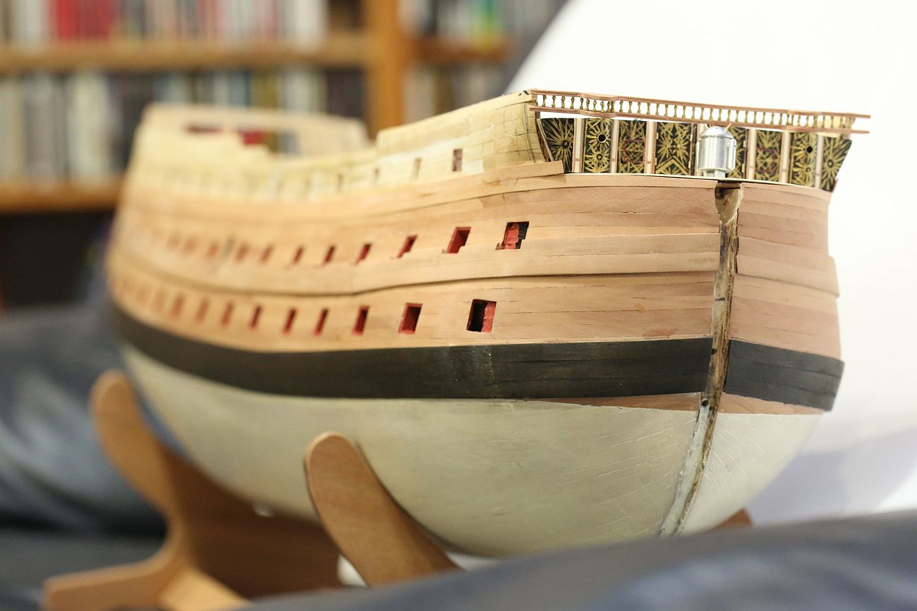
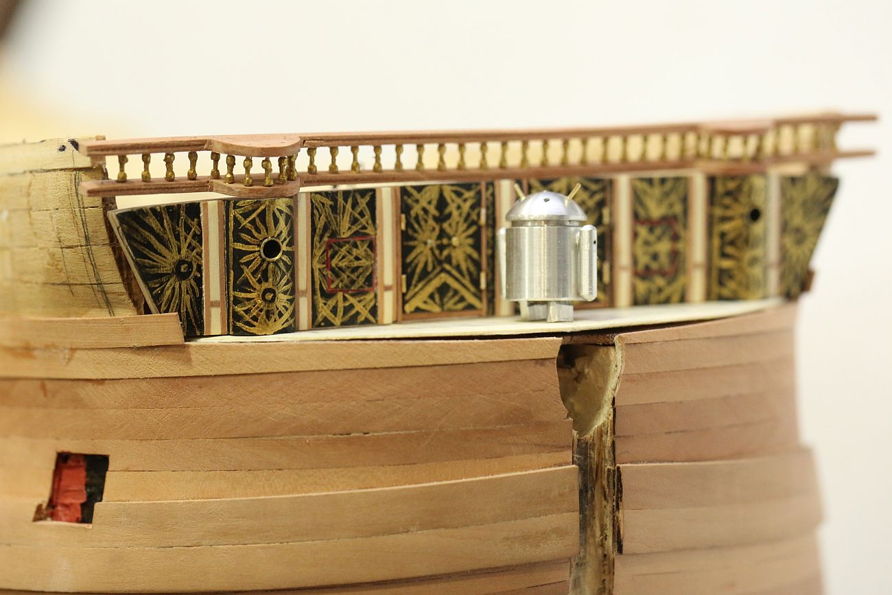
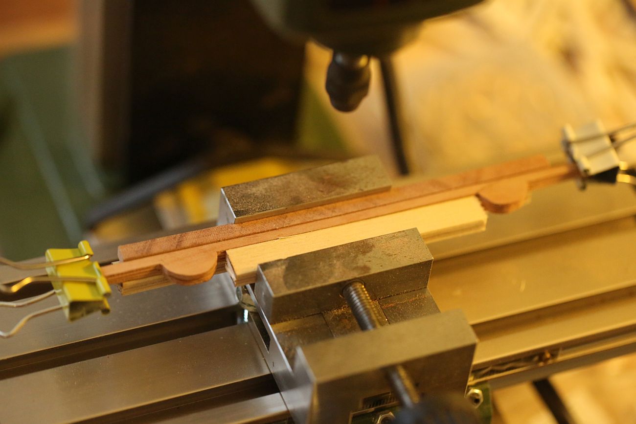
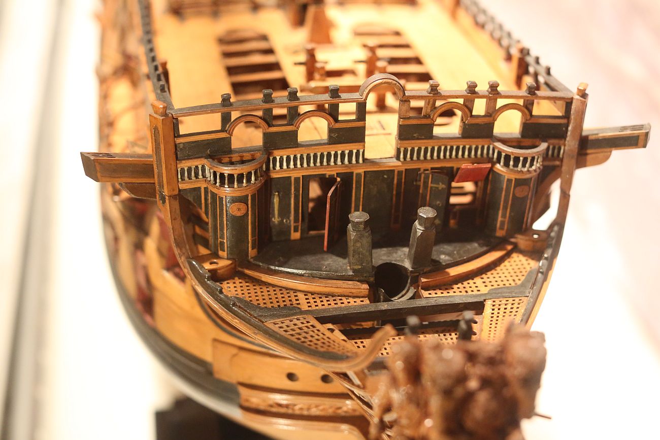
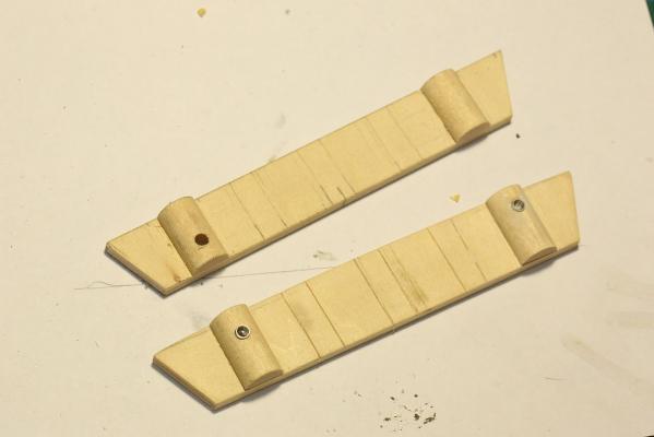
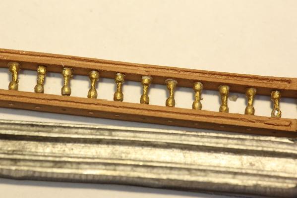
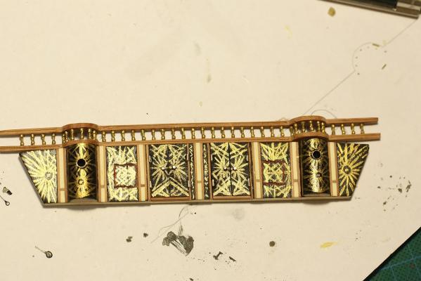
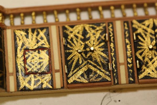
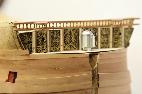
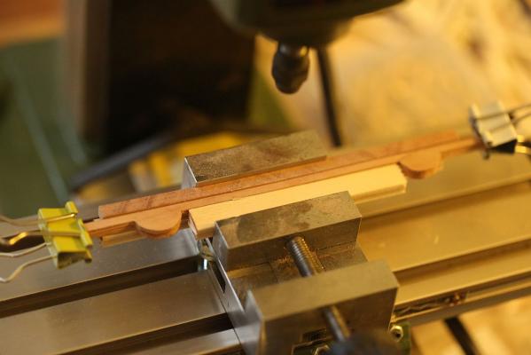
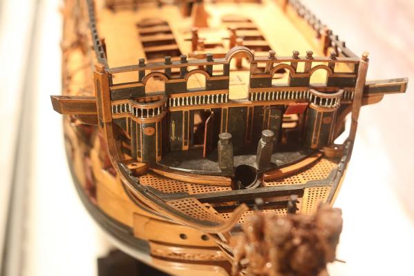
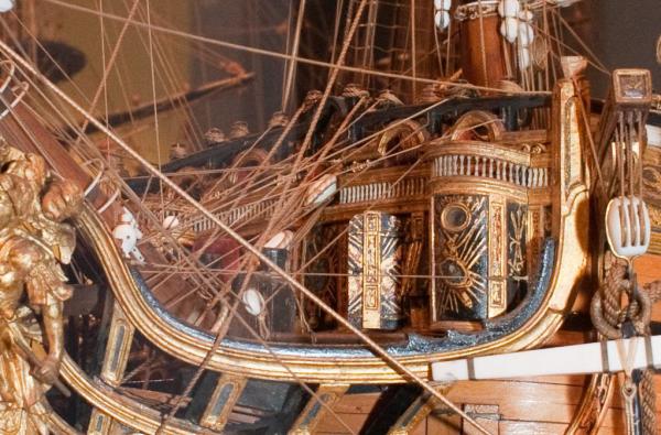
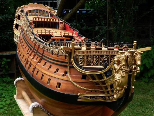
 Good morning! Time for an update. The scratchbuilt gun carriages have been completed - along with eye rings, simulated rivets, and quoin. The quoin handles were made from the heads of the smallest belaying pins I could find at my hobby shop (Float-A-Boat). At $2 for a pack of 10, this sure beat trying to turn them myself. A comparison of the kit supplied gun carriage and the scratchbuilt version with my 1/72 scale Android. You can see that it is exactly the same size and height. I ignored the suggested dimensions in the plans because I located the height of my gunports using the kit supplied carriage. This meant that I had to take the measurements off the kit supplied gun carriage but use a design which I completely copied from Chuck Passaro's practicum on MSW. You may wonder why there is a red stripe there. The answer - it makes it much easier to paint later. I painted the plank and installed it. That way, you get a nice, sharp line without having to mask. I haven't gotten around to painting the rest yet. You can also see that I have pre-drilled the holes for the gun rigging ... BEFORE the second planking layer goes on. This was a bit of foresight to prevent accidentally drilling holes from the inside to the outside and ruining the outside finish. I decided to scratchbuild the decoration that goes above the front bulkhead as well. Two strips of pear were cut with the table saw, then run through the thickness sander until they were 1.8mm thick each. They were then lightly glued together with PVA (generic PVA, NOT Titebond!). The required outline was drawn out in pencil, then they were carved together. After this, it was mounted on my mill to drill 40 holes, spaced 4mm apart (I do not own a drill press). This ensured that they were exact duplicates. They then were soaked in water. This dissolves the PVA and the pieces came apart. I am not sure if anyone has thought of this idea, I came up with it myself. If so, maybe I can claim to have invented a new technique! The balustrades were formed with my "bead on a wire" trick described earlier. They were then painted with metal primer (Admiralty paints), then painted gold (Vallejo Old Gold). After 24 hours curing time, they were pushed into the holes drilled earlier and secured with CA. This is a comparison of the scratchbuilt decoration compared with the part supplied by Euromodel. I think the scratchbuilt version looks miles better! I started work on the front bulkhead and the "seats of ease". Measurements were taken from the ship, then a ply template was created. I progressively shaved off wood until it fit the front bulkhead exactly. Here you can see two attempts - the first attempt was created before I realized that I had forgotten to take into account the camber of the fo'c'sle deck! Back to the drawing board, had to make another one. The seats were formed by cutting a 12mm dowel 60/40, and using the thicker piece. The windows for the seats of ease were turned from aluminum stock on my lathe. I am getting quite good at this now, I have to say! The walls of those round windows are 0.3mm thick! Front bulkhead completed and painted. A quick discussion of the painting of the front bulkhead is in order. Euromodel's plans appear to take after the model of the Royal William in the NMM. When I visited the NMM last year, I took this photo: As you can see, it is quite plain. However, the Royal William in the USNA collection looks completely different. I am unable to find a better photo than this one: It is much more elaborate. Victor Yancovitch's Royal William also shows a more elaborately painted front bulkhead: Having seen these, I came up with my own paint scheme. A close up of my painting, with a hidden message for my wife on the right pillar - her name and two hearts. Note the handles and hinges on the doors, as well as the inlay work. The gunport was carved square and a thin red line painted. For other RW builders: this is how the front bulkhead is located with regards to Frame 8. Note my mistake with terminating the planking early (earlier posts describe how I fixed it, but I didn't fix it enough). No matter, the second planking will be brought to the level of the front bulkhead and nobody will be any wiser. The front bulkhead dry fitted on the ship. Hello there!!


-
Thank you, Mark. Sergal it is for me, then.
-
Whoops, little speed bump there. Your repair looks fine, and i'm sure nobody will think of looking down there. Keep up the good work.
-
How to avoid table saw fuzzies?
Keith_W replied to Keith_W's topic in Modeling tools and Workshop Equipment
Thank you, Jeff. By the way, I have managed to cure it ... somewhat. I figured that SLOWING DOWN the rate which I make the cut would have the same effect as buying a blade with a higher TPI - in other words: by advancing the cut more slowly, more blades will hit the wood per unit of distance. This is the same as having a higher TPI blade and pushing the cut through quicker ... unless there is some other variable which I haven't considered! I do have a book on table saws which is on my Kindle reader. I have learnt so much from it, but I learn even more from actually making the cuts. I will try the masking tape. I love solutions that don't cost me money! -
Yes, I know you are watching my build. I see "likes" every now and then from you. A bit scary posting my work for all to see! Vasa is on my bucket list of things to build. I was wondering if you could comment on the Corel and the Panart, since you have built / are building both? If you could only buy one, which would it be?
-
That netting is a nice touch! It looks more like a real working boat now. Did you make it, or buy it?
- 425 replies
-
- 1
-

-
- bounty launch
- model shipways
- (and 1 more)
-
Make it look like brass
Keith_W replied to rcmdrvr's topic in Painting, finishing and weathering products and techniques
You can try Bare Metal Foil: http://www.bare-metal.com/bare-metal-foil.html It's basically an extremely thin self adhesive foil. Be careful, it's very fragile. The surface needs to be prepped thoroughly, because any defects will show through. -
How to avoid table saw fuzzies?
Keith_W replied to Keith_W's topic in Modeling tools and Workshop Equipment
Thank you all for your feedback. Jeff/Henry, I am not sure how to support such a thin piece, even with a sled? I will try out all the suggestions and report back. I have to fabricate two more batches of gun carriage cheeks in maybe a month, once I reach those decks. This time, I will: - have new blades, - make sure the direction of the grain is in the same direction as the cut, - construct myself a sled. I probably need one anyway. -
How to avoid table saw fuzzies?
Keith_W replied to Keith_W's topic in Modeling tools and Workshop Equipment
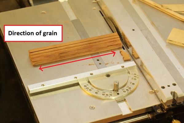
Mark, Rusty, figuerres, and Jeff - thank you for your responses. This is a picture of my Byrnes setup, as requested: - I am using the 80 tooth .04 kerf blade supplied by Byrnes - the blade height has been adjusted to just clear the top of the workpiece - I have indicated the direction of grain in the second picture - the wood being cut is Swiss Pear, supplied by Jeff from Hobbymill I guess I need new blades. I read Jeff's Byrnes Saw Operation page again last night (here: http://www.hobbymillusa.com/byrnes-saw-operation.php) ... i'll be ordering new blades.
-
Hi Rick, I will definitely need a set of your gunport hinges! I'm keeping an eye out on your thread to see when your final version is ready. A quick question - are you able to do one off photo-etch jobs? I can supply the drawings in .PSD (photoshop) format, which I understand can be converted to .DXF (AutoCAD) format. May not be so one-off, I think that other RW builders would be interested as well. I need the decorations done in Photo-etch, try as I might I am unable to think of a way to scratchbuild them.
-
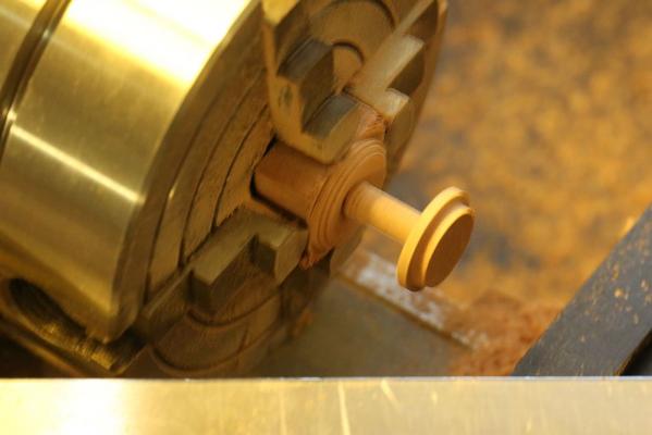
Hi Pat, I initially used the cutting tools for metal on the wood. Despite a lot of experimenting I could not eliminate chatter and poor finish, with a number of pieces breaking off. I only achieved success when I switched to my Proxxon woodturning chisel set. Till now I still don't understand why the HSS bit that slices aluminum like butter should utterly fail with wood! The procedure for making the capstan was as follows. Sorry, no pictures ... I was "in the zone" and did not feel like stopping to take pictures. - machine out a ring from tube aluminum stock using Sherline HSS cutter - cut out an appropriately sized blank of pear wood using table saw - mount blank on lathe, swap out the HSS cutter for the Sherline T-rest - turn the blank until it is cylindrical, check it is the correct diameter and sand it - swap position of T-rest to make the top cap of the capstan. Carve out a ring and make sure the aluminum ring fits. Cut off the top cap from stock. - use rotary table on Proxxon MF70 mill to locate and drill 8 holes, then plug holes with brass wire - in the meantime, turn out the rest of the capstan on the lathe - transfer the rest of the capstan to the MF70 mill. Using the rotary table and a 1.7mm end mill, machine 8 lines into the top of the capstan for the square holes. - glue the top cap back on the capstan - make the whelks and glue them on the capstan - mount the finished capstan back on the lathe and give it a final sand and polish. ... quite an involved procedure. That's why it took so long. (edit) oh yes. The biggest discovery of the day was that the four jaw chuck is a massive pain in the rear when it comes to mounting items consistently! If you remove something from the lathe and mount it again later, it will no longer be centered EVEN IF you do what I did - take note of the orientation of the piece AND the exact number of turns to tighten the jaws. If you want to remove a piece and still have it centered when you mount it back, use the 3 jaw chuck. However - 3 jaws can't hold square stock. So I carved the pear blank into a cylinder using the 4 jaw chuck. I then removed the 4 jaw chuck and mounted the 3 jaw chuck. Flip the pear blank around so that the chuck is gripping the cylinder, then carve the square stock round.
-
My first few kits were Artesania kits as well. Prior to this I had years of experience with plastic models, but even that was not enough to prepare me for the difficulty of making model ships out of wood. As others have said, the problems with Artesania are: - the ships are either fictitious, or not historically accurate, - fittings are recycled between kits, meaning that what you receive may be too big or too small. For example, oversized blocks or belaying pins. What Artesania is excellent at: - the wood is of excellent quality, and tastefully chosen. Having said that with nearly all their kits it is ramin, walnut, mahogany, and basswood. - extensive use of modern techniques - laser cut, photo etch, and cast metal parts. NO PLASTIC at all (i'm looking at you, Billings!) - the laser cut parts are usually very good - they fit together tightly without having to shim the frames. Usually they go together so well that you don't need a square to check that they are square. What Artesania is so-so at: - instructions can be a bit hit and miss. With most kits you get a colour booklet with photographs of the construction process. This usually stops immediately prior to rigging. Instructions in English are provided, but the translation is so awful that it is hard to read. Rigging instructions are usually so vague as to be close to useless - for a more complex ship, you will need to do your own research. Truth be told, there is a steep learning curve no matter which manufacturer you decide to go with. I think Artesania is not such a bad choice for a beginner.
-
Hello Max, thanks for your comment! That little robot is Google's Android mascot ... https://www.android.com/
-
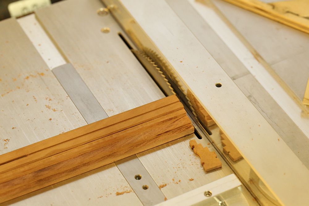
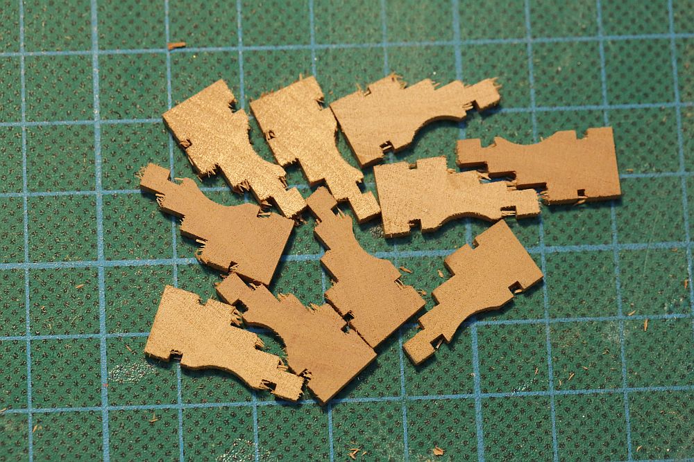
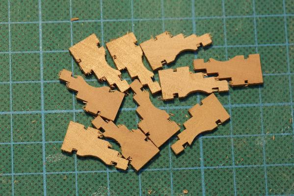
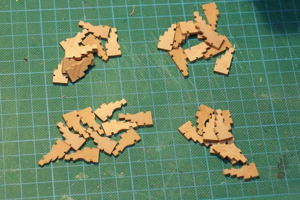
Today I made the cheeks of my gunport carriages and cut them out on my Byrnes table saw. I am generally happy with the results, except: You can see that the edges of the cut are not clean. The little splinters shave off nicely with a knife, but it is extremely tedious having to clean up dozens of these little things. You can see that the problem is more pronounced with some cuts than others, which makes me suspect that it is operator error rather than a problem with the machine (dull blade, etc). What have I done wrong? Am I feeding it too fast? Do I need to place closer attention to the grain? Do I need new blades? Or ... do all of you have this problem?

-
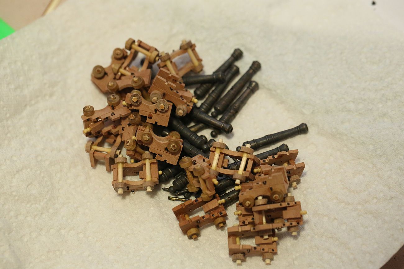
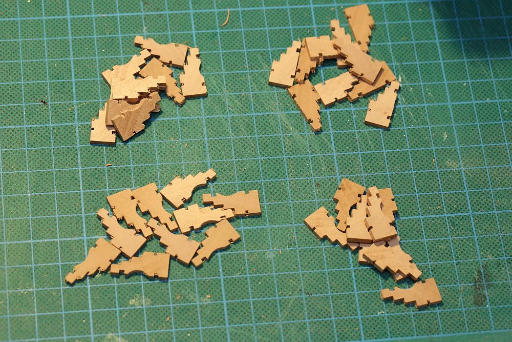
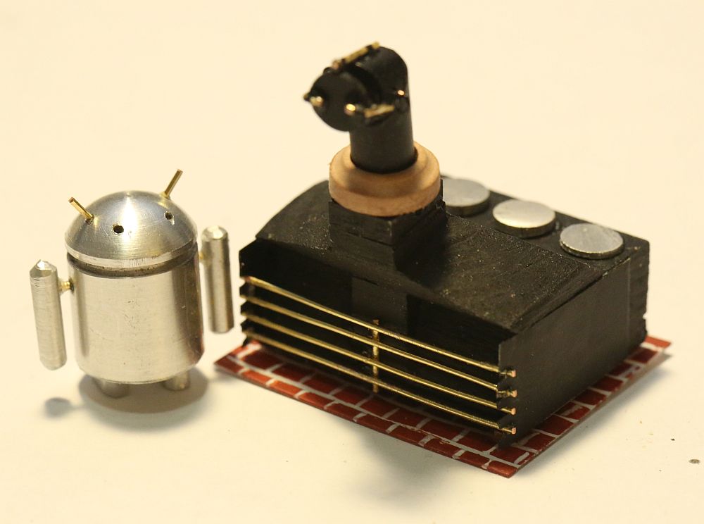
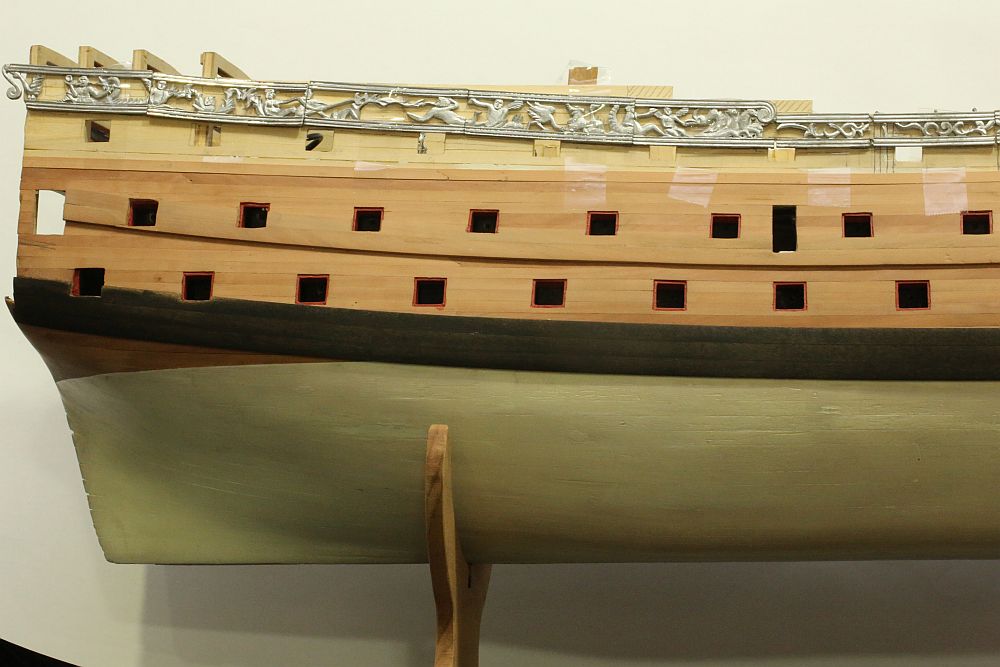
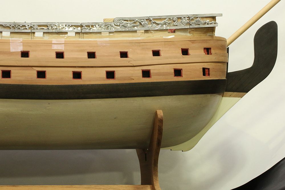
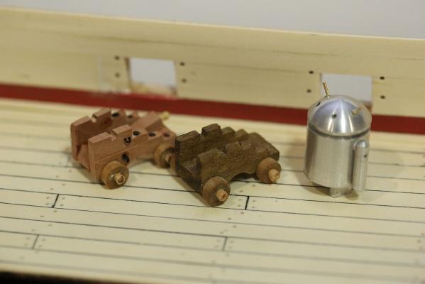
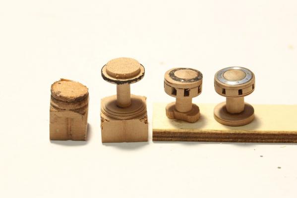
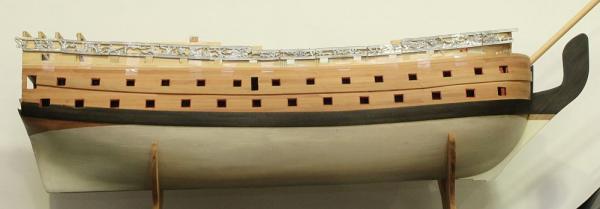
Hi all, thanks for the likes and commens! Time for an update. The wales have gone on the ship. The vertical bend was first achieved by soaking the wood for 48 hours, and then clamping it tightly to a jig. Once dried, they have to be used within hours of being removed from the jig, otherwise they will straighten up again! The lower wale was made from kit supplied walnut, dyed black. Once lightly sanded, the lustre of the walnut shines through the black.It is a marvellous (but totally unintended) effect. The walnut wale was incredibly difficult to get on. As noted by others, Feast Watson stains reject CA glue, even though they are water based! My first effort resulted in the wales falling off time and again until I thoroughly sanded off all the stain from the contact surfaces. The upper wale was made from pear, which I milled from a block supplied by Hobbymill. Pear is a much nicer wood to work with - it is softer, finer grained, cuts cleanly, and much easier to sand. It was MUCH easier fitting the pear wales than the walnut thanks to its bending properties. My first attempt at finding the line of the upper wale involved tediously reading the plans, but then it was much easier to simply run a compass across the top of the lower wale. Once done, the metal pieces were test fitted. This is a close-up of the metal pieces. You can see the difference between the metal pieces at the stern (which I have cleaned of all moulding flash), and the metal pieces at the bow, which I have not yet touched. Note that the total length of the pieces is more than adequate to cover the length of the ship, even will the side strakes taken into account. Having done all that, I started work on the deck furniture. I was not happy with the kit supplied capstan, so I turned my own on the lathe. It took me all day to make a capstan. Why? Because of numerous failures and because i'm still learning how to use my lathe properly! Here are the failures lined up before my final successful attempt on the right. I also fabricated the ship's stove. Note that I have deviated from the plans suggested by Euromodel. Euromodel suggests that the chimney is square and opens up directly to the sky. This means that any rain or seawater will fall directly into the fire, quenching it. My research suggests that chimneys were angled rearwards, and had a moveable cover - so that's what I made. The rest of the stove will be hidden below deck, so I did not bother detailing the stove very much. There IS detail from where the stove can potentially be seen - from the back (peeking below the deck), from the top (through the grating), and from the side (through the gunports). But the front of the stove is pretty much left as it is. The "bricks" that the stove is sitting on is simply painted plastic. I could have done a much better job if I had used masking tape, but I decided that nobody is ever going to see my shoddy paintwork, so I painted the bricks freehand. Many MSW members like to pose a scale figurine on their model. I thought I would get some practice with my lathe by turning a 1/72 Android figurine out of aluminum stock. Cute fella, isn't he? I have also made a start on the gun carriages. I first attempted to make these on the milling machine, but after cranking those knobs I became fed up very quickly. It was MUCH faster to make them on the table saw! That's it for now. Thanks for dropping in.


-
Beautiful sails! I can't really see what stitching pattern you are using, would you be able to post a close-up? Also, how did you manage to keep your sails so flat without puckering? The last time I tried to stitch sails, the fabric puckered up really badly!
-
Great work, Vince! I see you are using the same trick as me ... you worked out where the wales are going to be, and you are going to hide all your spiling under the wales! I also noticed that you carried your second planking all the way to the top. I thought that you were planning to leave it off to make room for the metal decorations? Very soon I will have to make the same decision - whether to plank all the way to the top, or just paint over the structural planking and fit the metal decorations on it. The difference is only 1mm, but the decorations are 2mm thick - i.e. the decision to leave the planking off will mean that the decorations won't sit as proud by 50% ... quite a substantial visual effect in my opinion. You may have seen in my build log that I lined off the gunports PRIOR to laying the second planking. This was because I decided that the gunport linings have to sit back from the planking by 1mm anyway (the thickness of the second planking), so it made sense to line the gunports before the second planking. I am curious to see how you line the gunports later. It's very fiddly work, I dropped a few planks inside the hull when I was working on it. Given that the lower hull is sealed, I could not retrieve the planks. So I squirted some glue in there, and jiggled the hull until I could not hear the planks sliding around any more
- 593 replies
-
- 2
-
-
- royal william
- euromodels
- (and 1 more)
-
How about an update photo of your build, Vince?
-
D'oh! I think I might have them as well! But I have already scratchbuilt my replacements for these parts. Never mind!
-
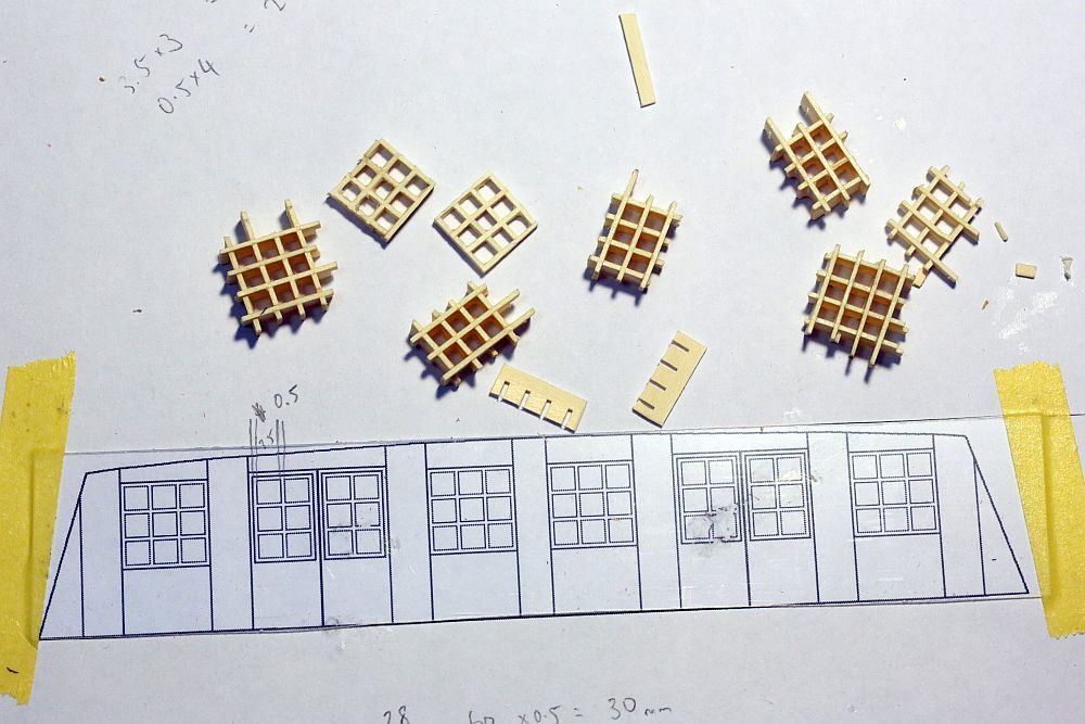
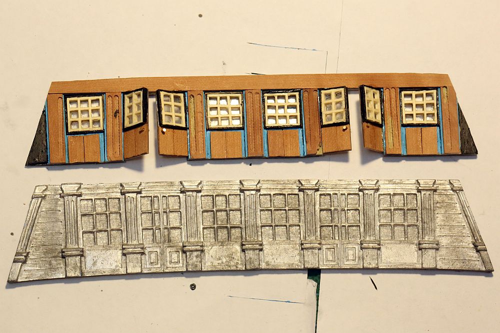
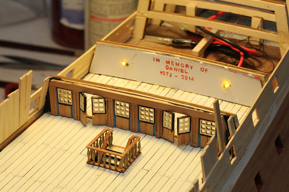
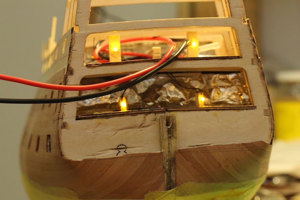
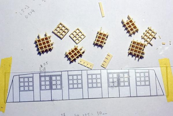
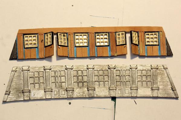
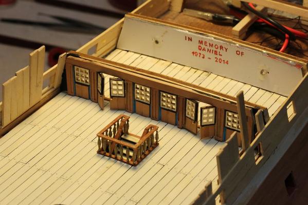
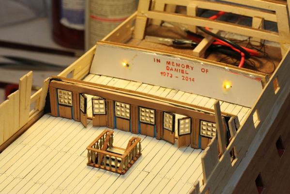
I finally finished shaping that annoying transom. Both part 54 and 55 are sitting in an ammonia bath at the moment, then will be boiled and then pressed to achieve the curvature shown in the plans. I found that the best way to shape both 54 and 55 is to dowel them together. Even then I found it difficult to offer it to the hull to check the shape, so I doweled it to the model as well. I forgot to take pictures. But I did get pictures for the replacement cabin piece that I made. As mentioned earlier in the thread, this is supplied as a cast metal piece which should be painted and then fit to the bulkhead. There is no other word for it - this piece is hideous. Thankfully it is hidden away under the quarterdeck, so I could have gotten away with using it if I felt lazy. But I thought I would give it a whirl. This is what I enjoy most about modelling ... actually making stuff out of wood! The windows were made by cutting slits in some thin holly and fitting it together as you would fit grating. It was then thinned down on my disc sander down to 1mm, then glued on a sheet of clear styrene. You can see this piece compared to the chunky metal piece supplied by the kit. I would normally discard it, but I found a use for it. ... I painted it with a hidden message to remember my best friend who passed away last year. I also installed some lights to light up the cabin from within. The stern LED's have also been fitted.

-
Thank you janos! IMO your technique deserves a separate thread so that people can see it.
-
Janos, I am very interested in your technique, however I have difficulty picturing what you are describing. Do you have a picture of your procedure somewhere? And if you don't, would you be able to post it?
-
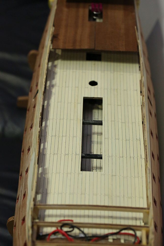
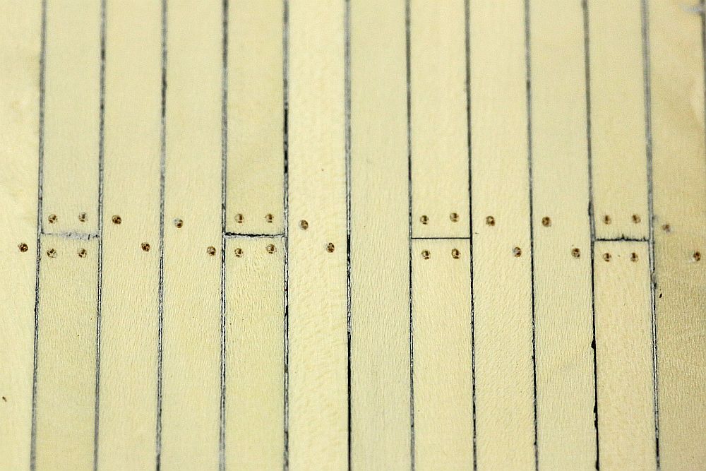
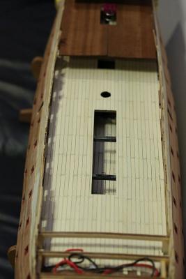
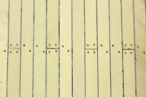
Oh yes, I forgot to show you these pictures. The main deck has been planked and treenailed. The planking was done in a 3 plank shift pattern. I did a few experiments to simulate the caulking, including edge gluing black card, black paper, and black tissue paper. My problem with this method is that the paper tends to tear, no matter how sharp my scalpel is. This leads to caulking of irregular thickness. In the end, I clamped a whole bunch of planks together and painted both edges. I went over it 3 times to get a decent thickness of paint. Once sanded, it looks OK. I am happy with it! The treenails were made from bamboo, drawn through a Byrnes draw plate. I was initially not happy with my Byrnes plate, because it kept clogging up with wood fiber, and I would have to clean out the plate after each draw! Then I worked out that I was pulling the dowels through the Byrnes plate the wrong way! Once I corrected that, it became a dream to use. These bamboo dowels have been pulled down to 0.5mm. The effect against the holly is subtle, but it's exactly what I want.
-
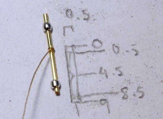
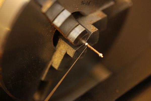
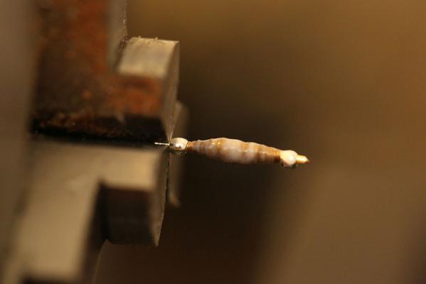
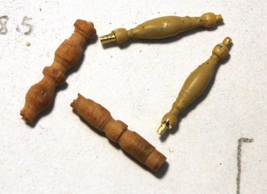
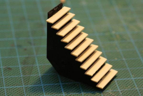
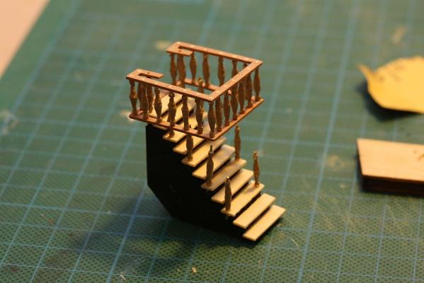
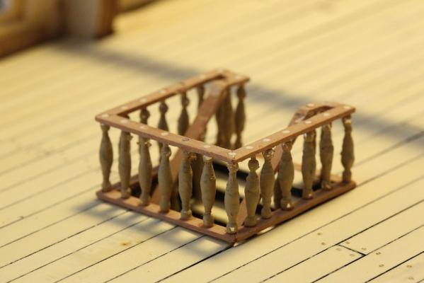
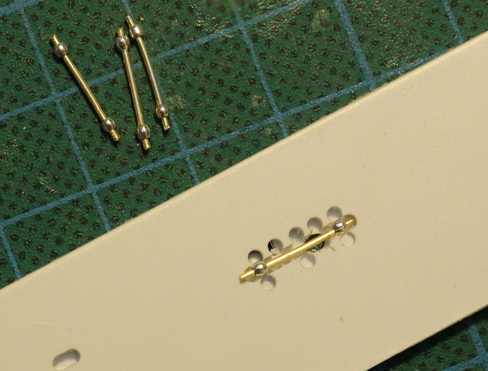
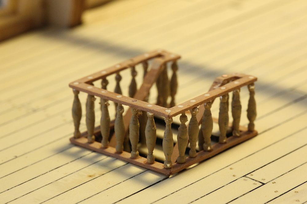
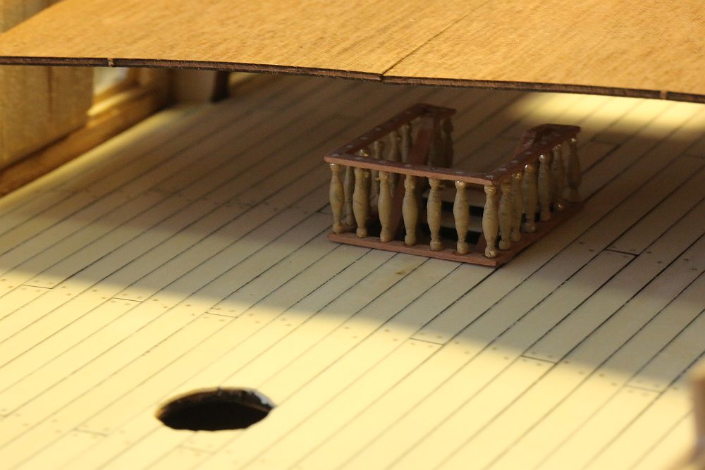
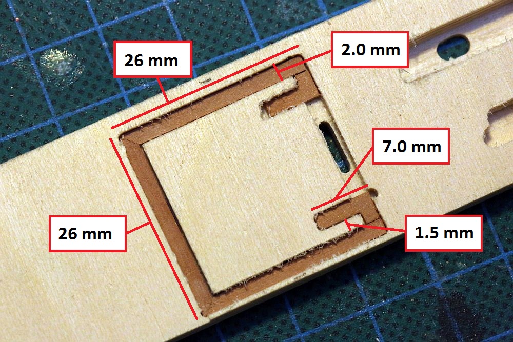
Took a break from fabricating those infernal transom parts to doing something which was more fun. I made the staircase from the main to the lower deck. This piece will be mostly hidden so I used it as a trial run for other staircases I will have to build. First problem - the balustrades. The kit does not supply any. Commercially available balustrades can not be found in the correct size (or perhaps I am not looking in the right places). The plans suggest balustrade dimensions 9mm x 2mm, and I would agree. 3mm balustrades look too thick and awkward. I fabricated my own. Those who are following this thread may recall an earlier post (here: http://modelshipworld.com/index.php/topic/7195-hms-royal-william-by-keithw-euromodel-172/?p=278928 ) where I came up with the idea of threading beads on a wire. I refined that idea a little: First set up a production line to superglue the beads in place. Tie a thin thread to the wire, superglue the knot, then cut the thread flush. Wind the thread around the wire until a bulb is formed (I used my lathe at very low speed). Keep adding superglue. The idea is to impregnate the thread with superglue to make it possible to turn on a lathe later. Once done, add a layer of liquid sculpey. Bake the batch in the oven according to the Sculpey instructions (15 min at 150C). Turn the balustrades on the lathe until happy with the results, then paint. This is a comparison of the BEST effort I made with turning pear dowel on the lathe (on left) with the Sculpey-thread-bead method (on right). The problem I had with turning pear dowels is that they snapped off the lathe once they reach a certain thinness. I could never get them below 2.5mm - still too thick. To be honest I am satisfied with neither of them. The sculpey-thread-bead method does produce a superior looking balustrade, but it is VERY time consuming, VERY fiddly, and VERY inconsistent. I decided to accept the results since the staircase will be hidden, but I will need to find another method. I might try turning brass or maybe even bone. Anyway, I continued with construction. I made a jig to make sure that I aligned the various planks for the handrails properly. I decided not to follow Euromodel's plans and came up with my own dimensions (which I have supplied), because I think it looks better! Once done, I stacked both squares and drilled holes simultaneously through both, to make sure that they would align once the balustrades were fitted. Staircase construction. Given that it would not be seen, I decided to simply paint the jig black. It would be more sturdy and easier than constructing an actual staircase. Staircase in position! It is mostly hidden by the quarterdeck. The my Canon macro lens (100mm f/2.8) is ruthlessly revealing but it actually looks pretty good.