Keith_W
-
Posts
1,145 -
Joined
-
Last visited
Content Type
Profiles
Forums
Gallery
Events
Everything posted by Keith_W
-
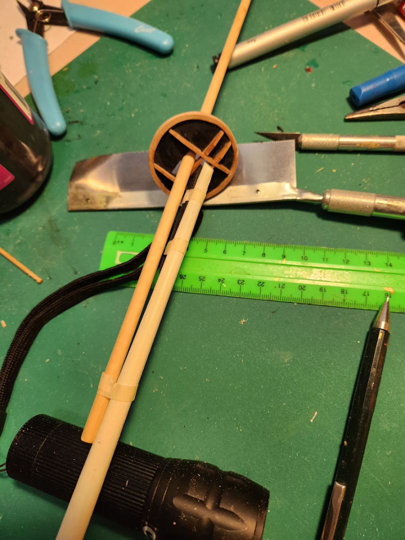
 Hi @piratepete007, I managed to find the answer in Ken's build log. He shows a clear picture of how the whole assemble works in this post. It looks as if I have arranged the pieces correctly.
 -
MSW is extremely slow
Keith_W replied to Keith_W's topic in Using the MSW forum - **NO MODELING CONTENT IN THIS SUB-FORUM**
Well, it looks as if the issue has solved itself. MSW is still slower than the other websites I visit, but at least pictures are loading now. A ping still shows 206ms response time, but now 0% packet loss. -
If you ever enter a model competition and don't win a prize for this, then there is no justice in this world. This is THE most amazing model of the Bismarck I have ever seen, and I have seen quite a few! Well, maybe the one in the Munich museum is better, but this one comes very close.
-
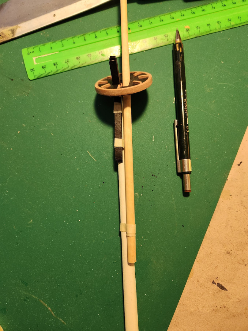
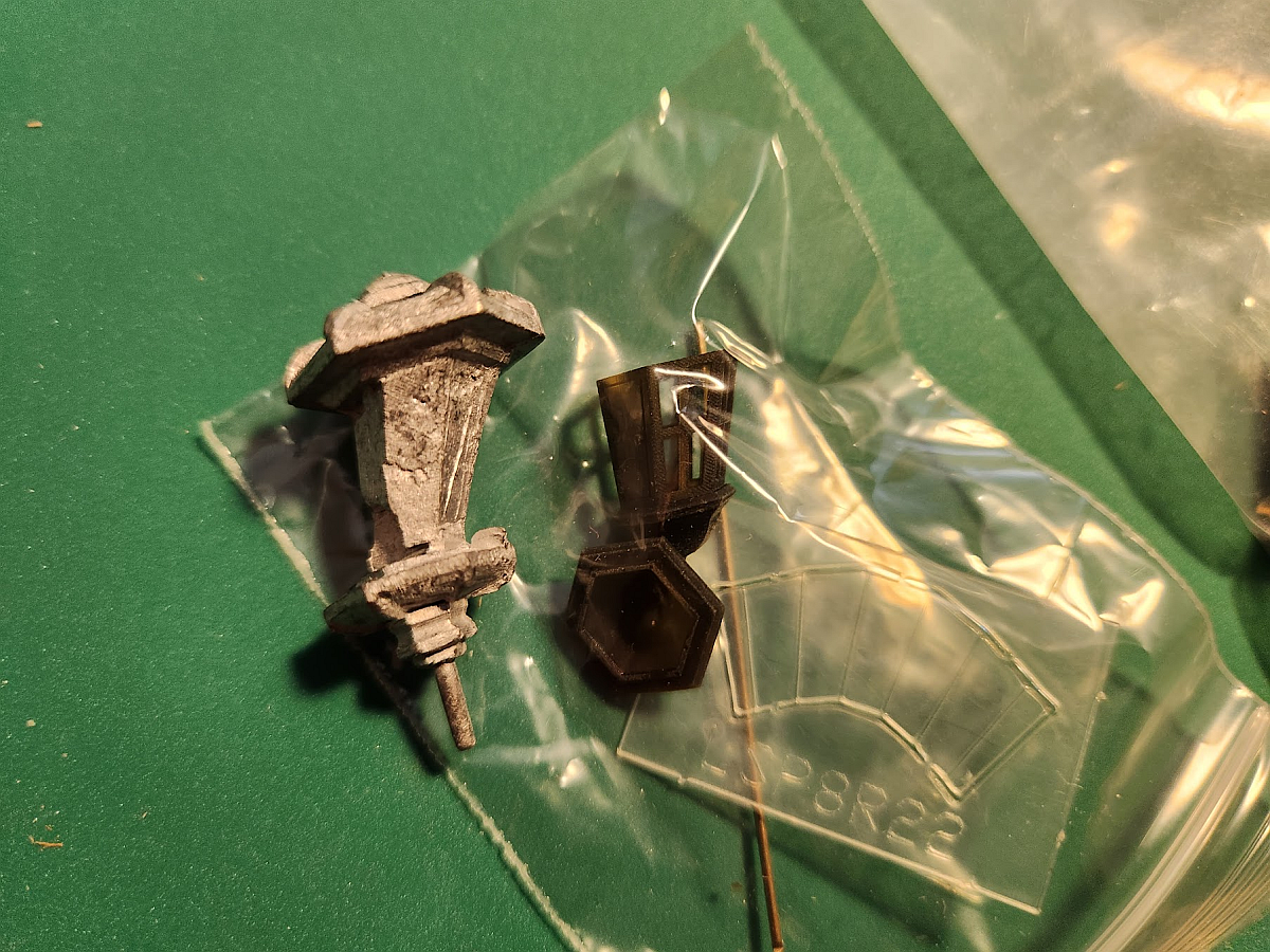
Hey @piratepete007, I have a question for you. I am trying to figure out how to mount the jibboom on the bowsprit. Have I arranged the pieces correctly? The knee (in black) is in line with the bowsprit, and the jibboom is off to the side. I think this looks strange, but that's what the plans seem to indicate. I think having the jibboom in line with the bowsprit in the midline looks more correct, but the knee is shaped so that it will sit on top of the bowsprit.
-
I was planning on making my own rope. But then, Byrnes stopped making their rope walk. And ordering a rope walk from Syren will take as long to arrive as ordering their rope. And there is no guarantee that my rope will be better quality than theirs. Most likely not!
-
Unfortunately I failed to plan properly and I don't have enough rope to move on to the rigging. I want to replace the kit supplied rope with Syren rope. I ordered a few samples of rope from Chuck many years ago as part of a larger order, and I was really pleased with the quality. Trying to calculate how much rope to order was quite difficult, I had to measure every strand of rope I could see to get an estimate, then added 50%. THEN the Syren store was closed and I could not get my order in until the weekend. 20 days to get the rope to Australia. So I will move on to making other parts that do not need any rope.
-
Bugatti Type 35B by CDW - FINISHED - Italeri - 1:12 Scale
Keith_W replied to CDW's topic in Non-ship/categorised builds
Great job! Is everything you have done so far part of the kit, or did you buy some aftermarket parts? The last car model I built was > 20 years ago, I am amazed by what's in a kit these days. -
MSW is extremely slow
Keith_W replied to Keith_W's topic in Using the MSW forum - **NO MODELING CONTENT IN THIS SUB-FORUM**
Thank you James. This problem is intermittent and it is excruciating. Quite often pictures fail to load, which takes away a lot of enjoyment from this site. I note that nobody else has complained of the same issue, so hopefully it's just a temporary thing and it will go away. -
Some comments: 1. I would apply the keel before the second planking. That way, if the keel is mis-shapen or does not fit properly, it will be partially hidden by the second planking. In fact, I would have done it before the first planking, but too late for that now. It also depends on the keel thickness - if it is too thick, it can be sanded down. But if it's too thin, there is no way out. So check the keel thickness as well. 2. I suggest you remove all those nails before you sand for the second planking. It will interfere with your sanding and make the surface irregular. 3. You used way too much filler! No drama, it can be sanded off. But filler should be used sparingly. I sand the hull with #80 grit first, and then inspect for dips and holes. I wipe on some filler, and immediately wipe the excess away. I hate sanding, and I especially hate sanding filler - so I use as little of it as I can.
- 24 replies
-
- 1
-

-
- OcCre
- bounty launch
- (and 1 more)
-
MSW is extremely slow
Keith_W replied to Keith_W's topic in Using the MSW forum - **NO MODELING CONTENT IN THIS SUB-FORUM**
Hello OC, as I mentioned in my post, and as the ping shows, all other sites are not affected. Only MSW. -
I am not sure if other people are experiencing this problem, but MSW is very slow for me. Doing anything on MSW - trying to open a thread, look at new posts, do a search, open a personal message, etc. seems to take forever. It's not my internet connection because every other website I visit is very fast. This is what happens when I ping MSW: As you can see, 50% packet loss from one ping. Is this a known issue? Can admin do something to fix it?

-
Hello kirill. I will partially furl all the bottom sails and the middle sails, and keep the top sails unfurled. I have a HMS Bounty with all the sails unfurled (see my signature). In my opinion it hides too much.
-
Spasibo, Kirill! I looked over the museum pictures you posted. Wow, amazing ... did you make those models?
-
Hey Chuck, I need to buy some rope! But your store is closed for maintenance. When will it reopen? I also want to clarify - on your webpage, you say that your rope is supplied in 29-30' packs. I am not American, I presume that means 29-30 feet? Or about 9.14 meters of rope per pack? I have some rope from Syren that I bought in a previous order (maybe 5-6 years ago), and there isn't 30' of rope per pack. I just measured it, the length of rope that I have is 19' in a pack. Have your packs gotten larger?
-
Thanks guys. I have a question - as you can see, the gunports are open and the guns are run out, implying readiness for battle. I want to display the model with sails, but I do not want to cover up the deck details. Would it be accurate to depict the bottom sails furled (or partially furled), with the top sails fully deployed?
-
I can sell you mine, I don't use it very much. I am in Australia though, and the power plug has been modified for an Australian power socket. It is 240V. Inbox me if you are interested. I suspect shipping will be VERY expensive, given that I don't have the box for it and even internal postage within Australia for something as heavy as this costs a lot of money!
-
This is simply amazing! I don't have the eyes or the steady hands to work on such small scale. I have a question though - if the swastika is banned in Germany, does this mean you can not display the model in a public place, like a model show? When I attended the last model show, I had a discussion about the swastika with a fellow modeller. He thought it was right to remove the swastika. I said that history is history, just because you depict a swastika in a model that is supposed to have a swastika, does not mean you support Nazism. If it disturbs you, then don't make the model - choose another subject that can be accurately depicted without causing offence. Even in Australia it is controversial!
-
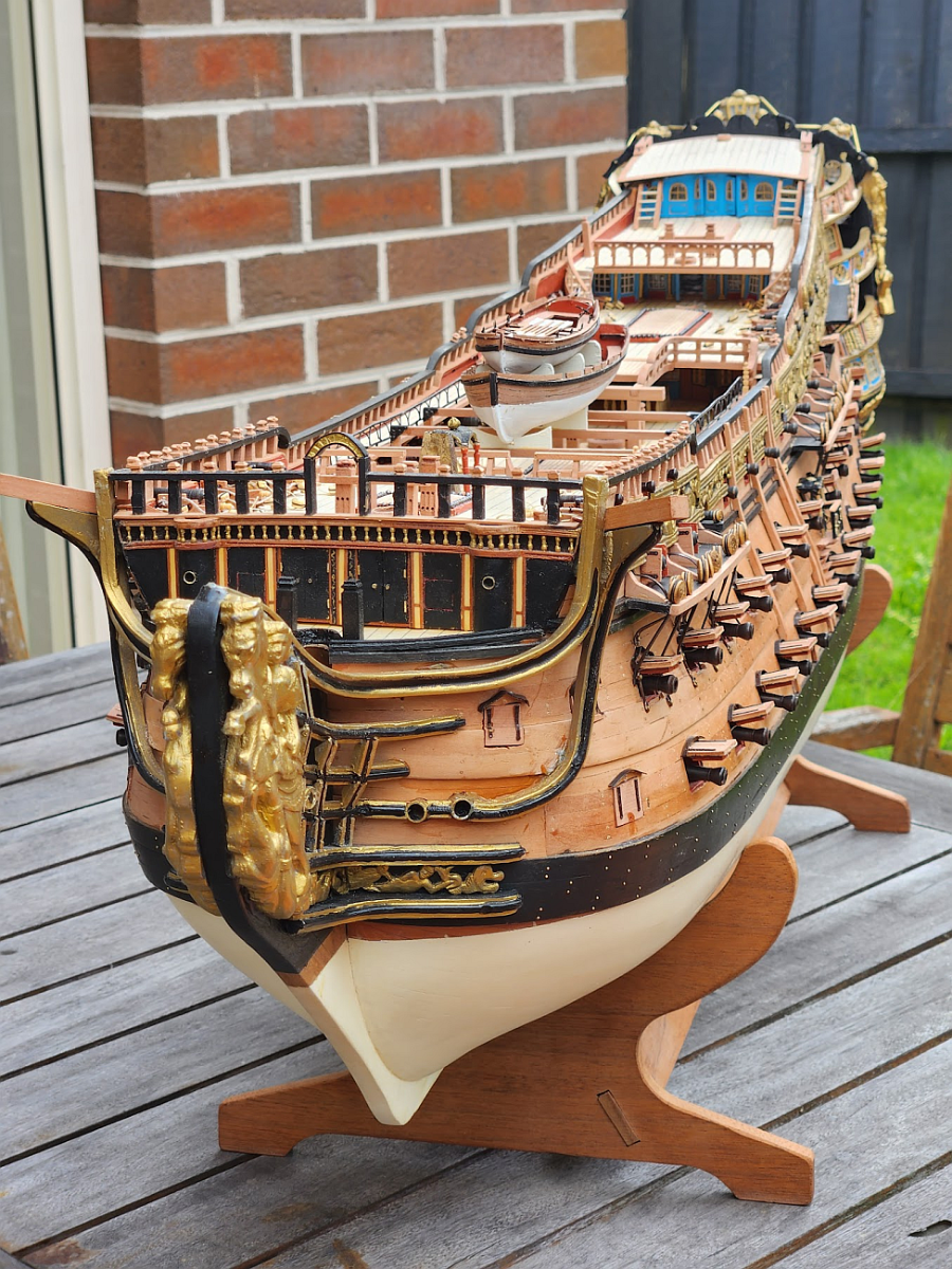
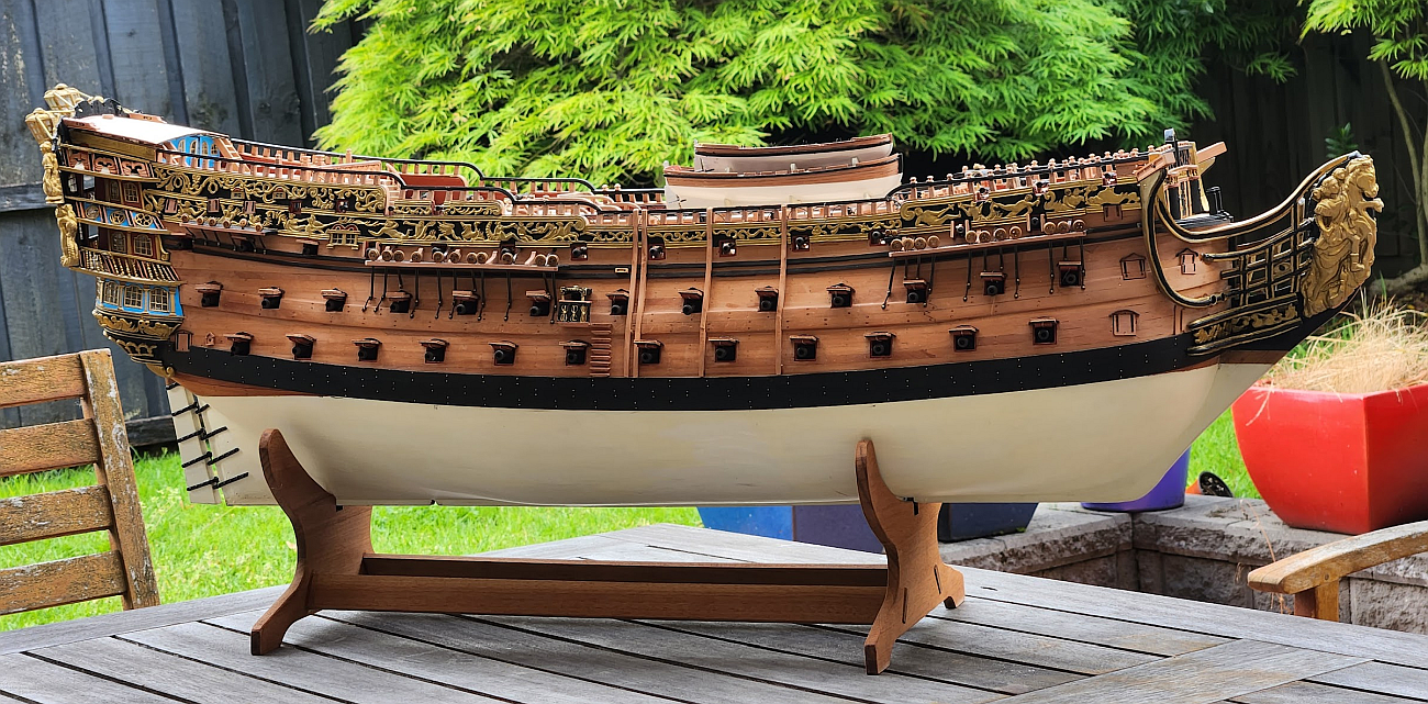
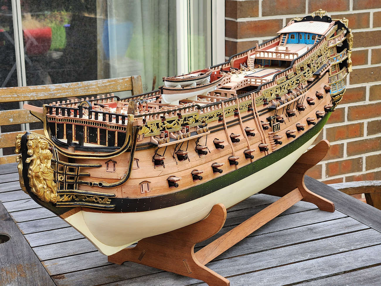
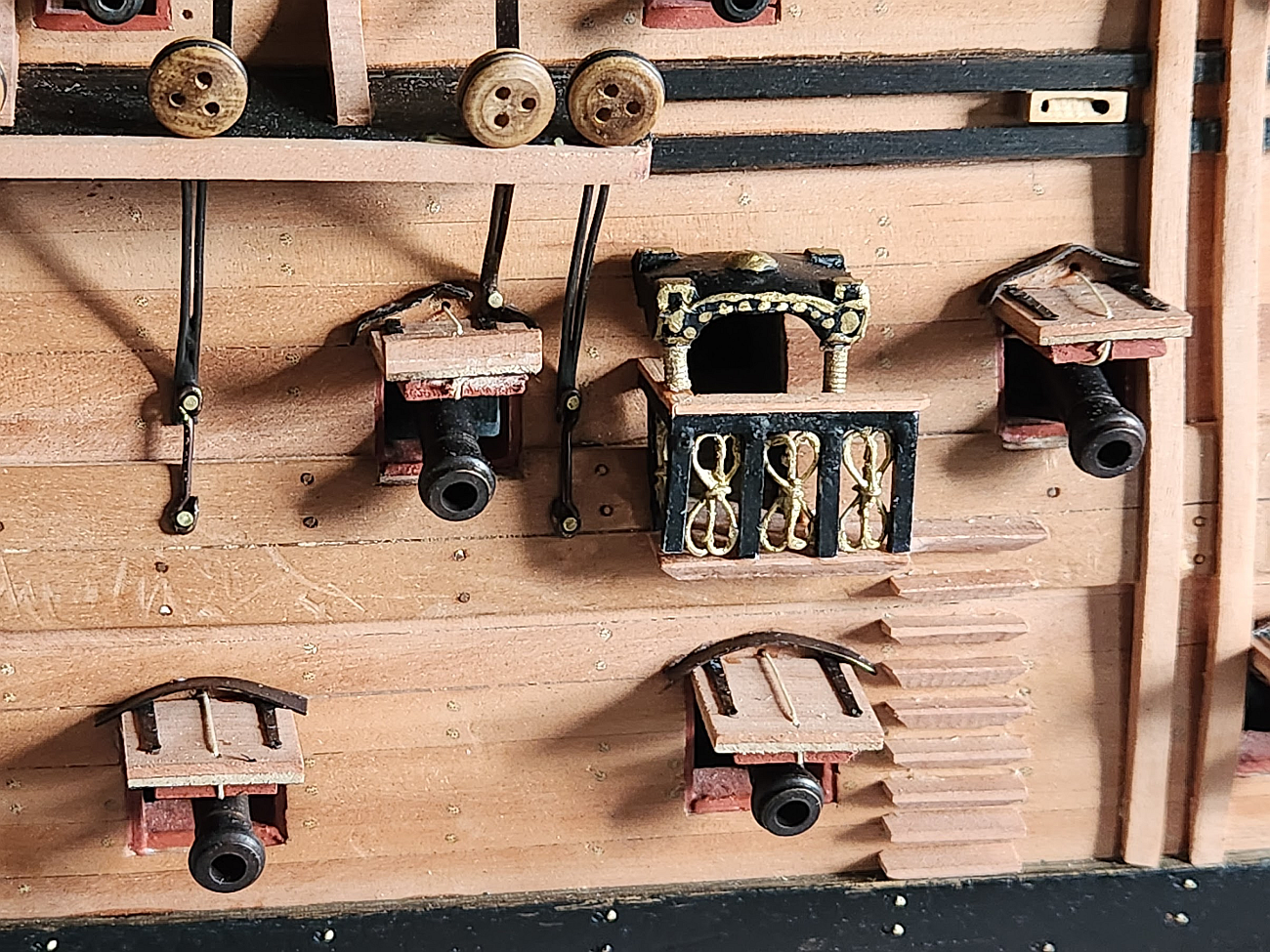
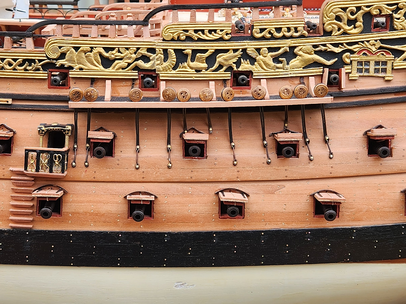
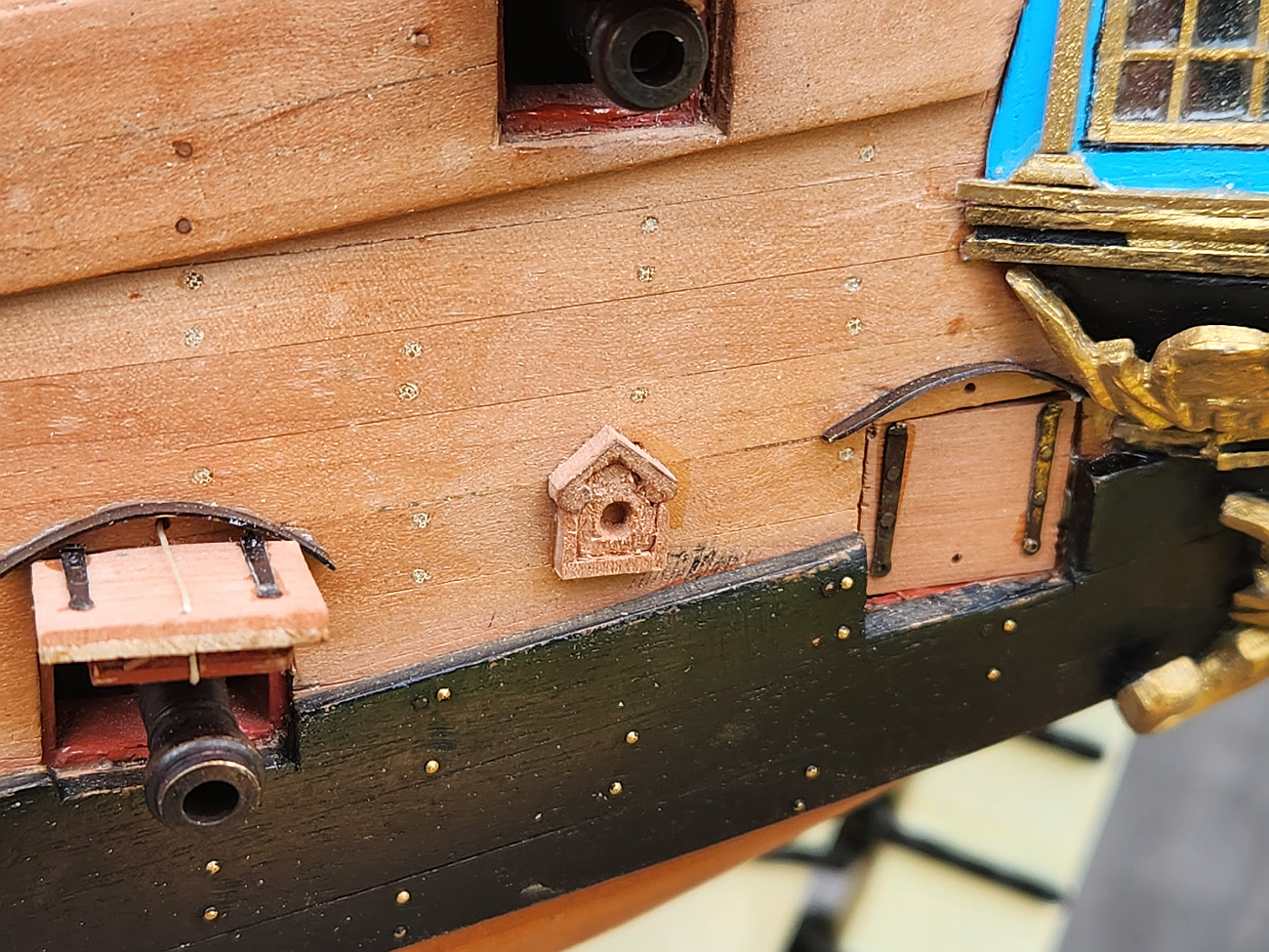
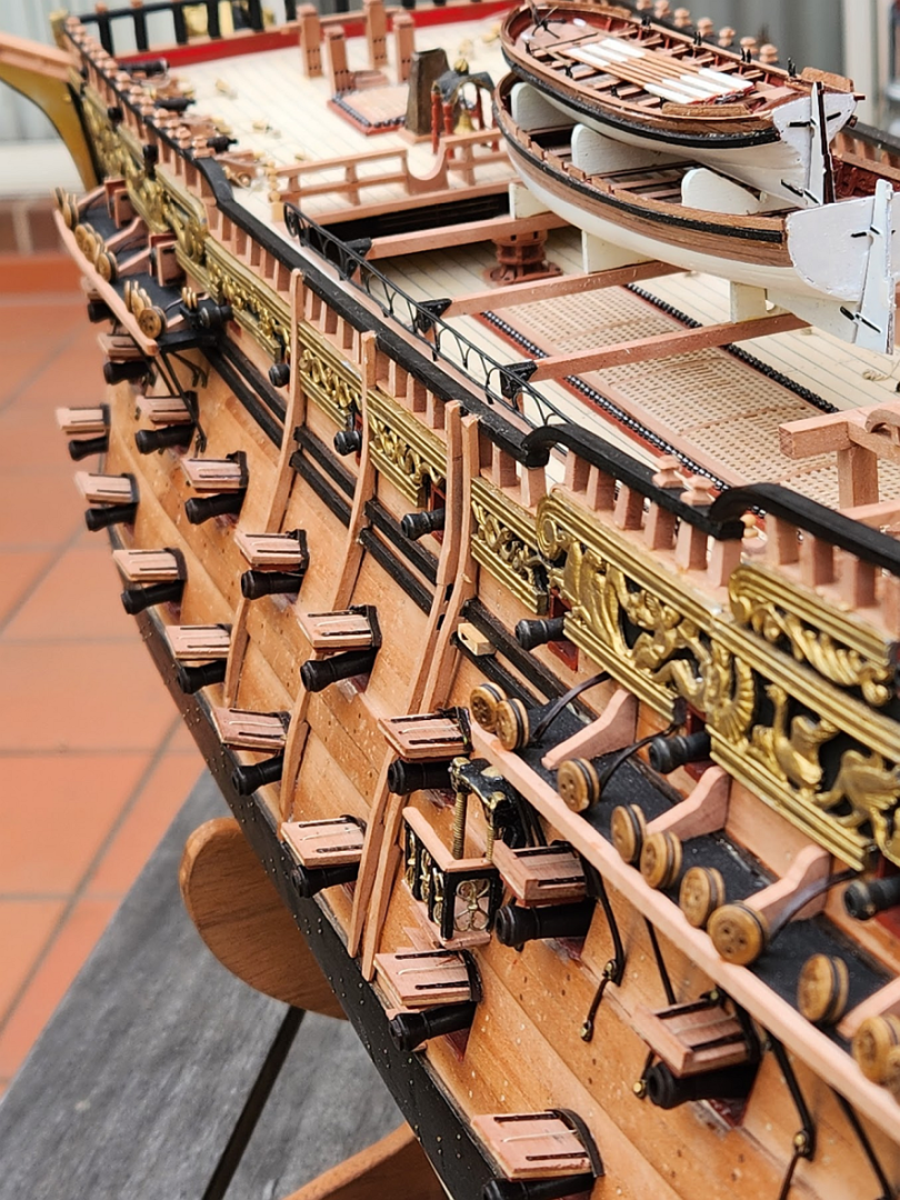
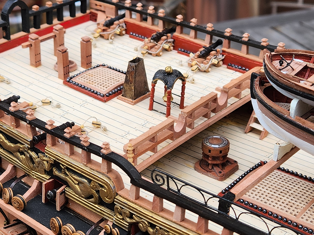
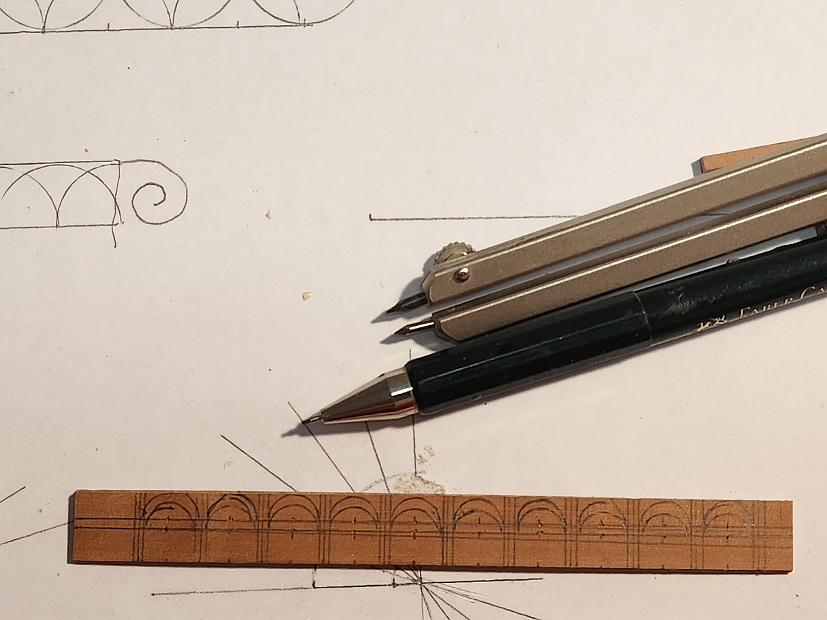
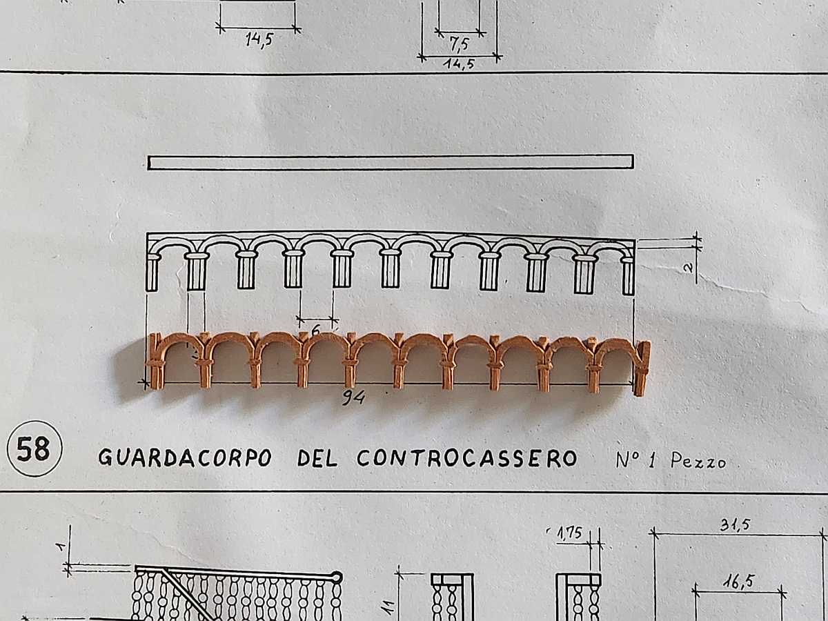
Hi again, and thanks for the likes and comments everyone. I have reached another major milestone - the hull is finished, and it is time to move to the masts and rigging. In preparation for this task I have been reading other RW build logs on MSW and I am amazed by what other builders have done - @marktiedens, @ken3335, and @pirozzi. I enjoy rigging the least because rope has a mind of its own and it never goes where I want it to go. But it's something that has to be done! Here are some photos with highlights on some ship features. Some vanity shots taken outside. Entry way. As per usual, I did not use the kit parts. The railing was made by coiling some fine brass wire around a jig, then flattening it in a vice, then painted. The columns were made by wrapping the same fine wire around a brass rod and painted. The roof was the kit part. Note the taper on the underside of the steps, this was quite troublesome to make. I milled out a "V" groove on my Proxxon MF70 and then sawed it in half. Then each step was shaped with a Dremel. The shroud stays reach down to the wales. The bottom stay has eyes for nails - these were too large (as noted in other build logs), but instead of replacing them I flattened them with some pliers. They were also pickled in some blackening solution because I did not like the shiny brass - it called too much attention to itself. The angle of the stays was set with a string tied to a dummy mast. The rigols were made from brass sheet and blackened. I could not find brass strip of the correct size and thickness, so each rigol had to be individually cut out of the sheet. The cutting process leaves them curled, so they had to be flattened in a vice. I found that the cap of a Vallejo paint container has the perfect curvature to form the rigols. Here is a carved chesstree. My carving skills are quite rudimentary and I was unable to obtain the finish that I wanted. Still, the part and the imperfections are small enough that hopefully they won't be noticed. The gunport hinges were from @rshousha at Modeller's Workshop. They are a bit too short, but far preferable over the overly thick kit supplied part. Roughtree block. It has all the features indicated in the Euromodel plans, but it has been slightly restyled. I realized I haven't posted a clear shot of the fo'c'sle deck so here it is. Note the fo'c'sle deck railing which deviates from Euromodel's plans. My research suggested that the beam supports should be round. Indeed this was depicted in the RW in the NMM in Greenwich. So I rounded the bottom and made them thick and sturdy.


-
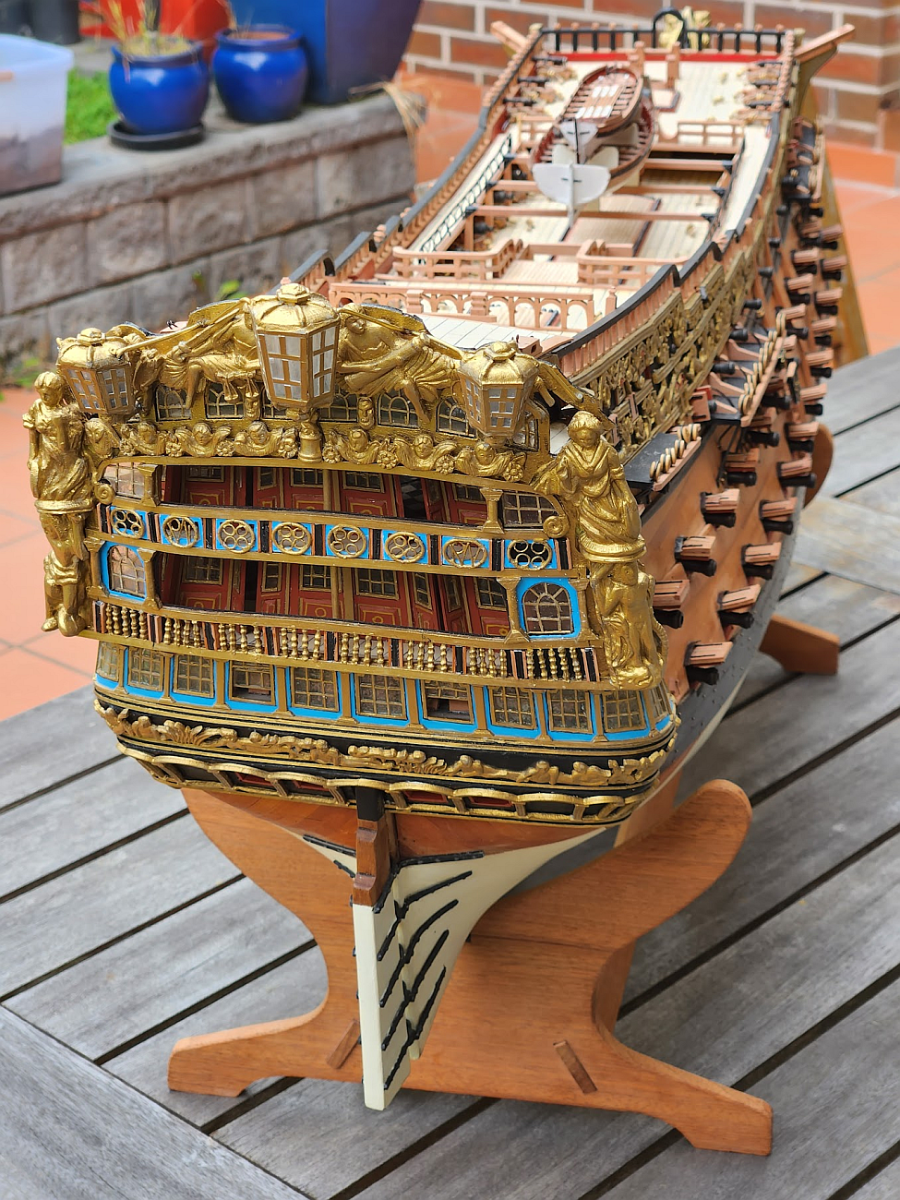
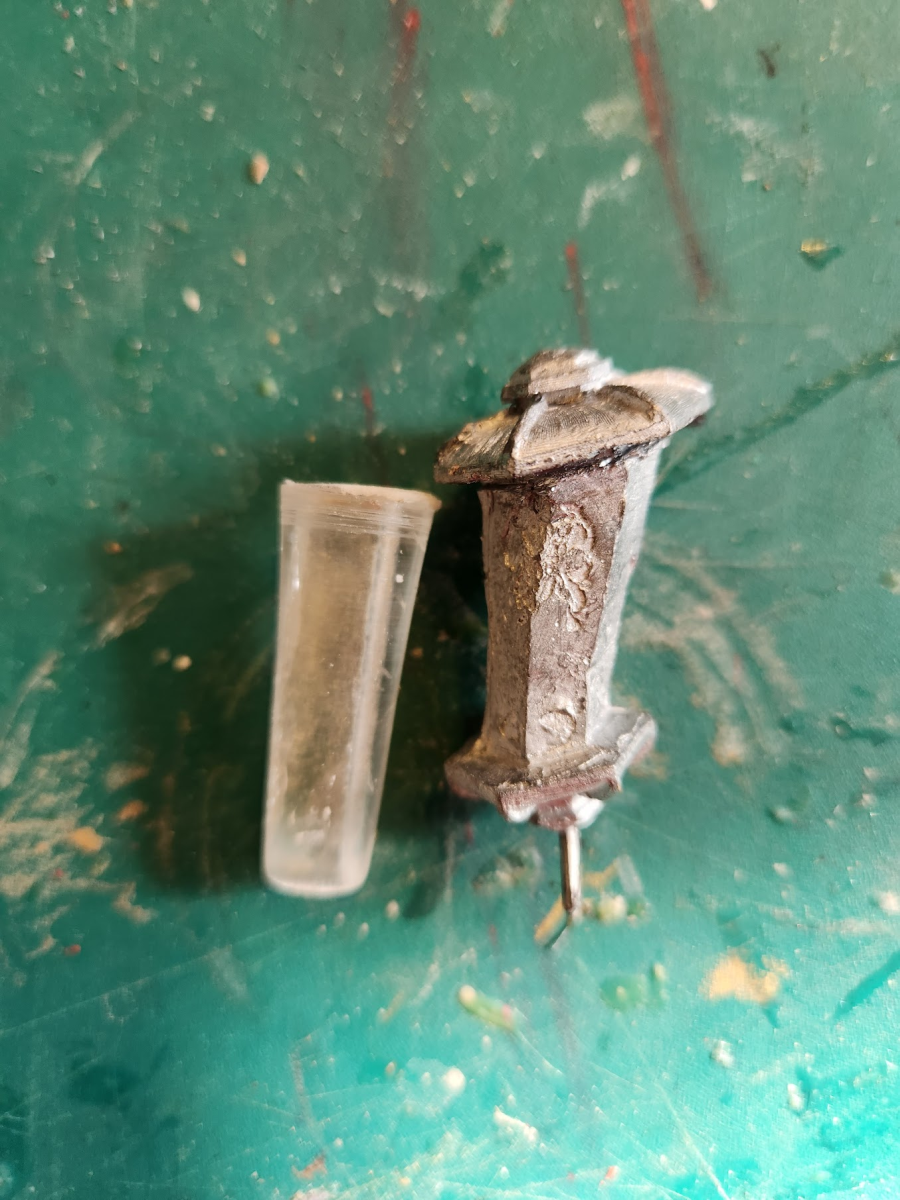
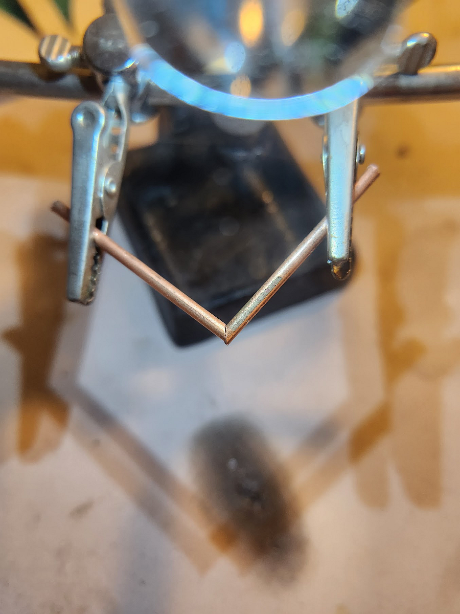
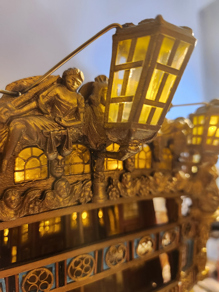
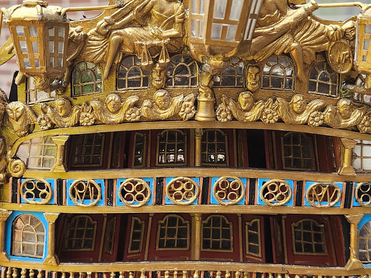
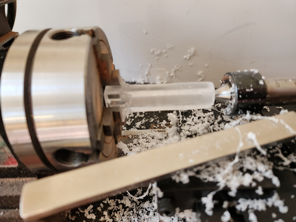
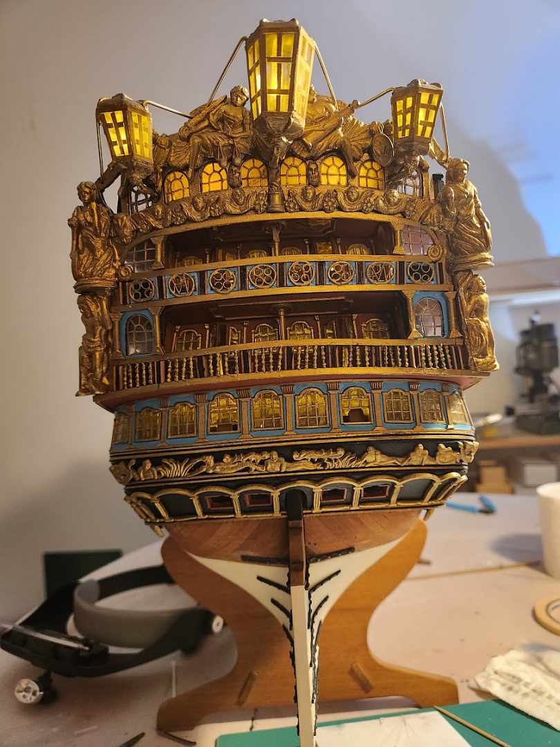
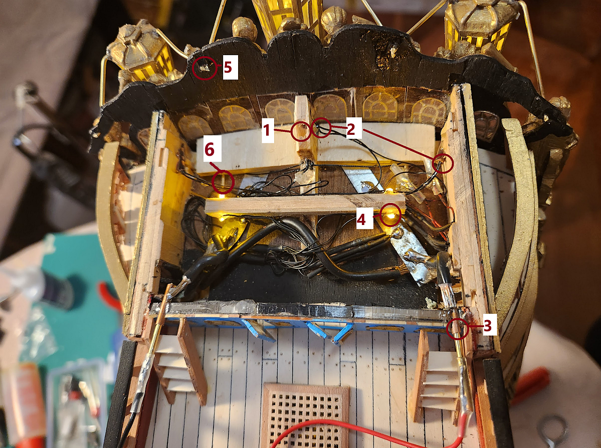
Now I tackled an area which has been of great concern to me since I started this project - the lanterns. Euromodel supplies the lanterns as a solid cast metal part with metal plates for the windows. If you look over all the other RW build logs on MSW, every other modeller has elected to paint the windows. I thought this would look out of place in my model, since I had fabricated all the windows so that they are clear and can be backlit. I wanted the lanterns to light up, so I ordered the largest lanterns from Vanguard Models: They are little jewels compared to the poorly cast Euromodel part. But sadly, they were too small and I can't use them. So I had to come up with my own solution. Sadly I did not take photos of the complete process, so you will have to rely on my description of what I did. The solution was to cut off the top and bottom of the Euromodel lantern, and fabricate everything else in between. The central support would be an acrylic tube which had to be machined to size. Since I did not have any acrylic tube, I had to make my own. I did this by THOROUGHLY CA'ing sheets of acrylic together and then machining it on my lathe. This is an incredibly messy process and the tube becomes really fragile just as it starts to reach the proper dimension. I needed 3 tubes for 3 lanterns, I had 5 failures - all fractured just as I was about to reach my goal. Here is a completed tube next to the Euromodel lantern. I copied the dimensions of the cast central support exactly but did not bother copying the squared off facets because I would not be using the lantern face plates supplied by Euromodel. Next problem was the lantern support. It had to be hollow so that the wiring of the LED's can pass through it. I tried bending the tube, but it crimped at the bend and the wires could not pass. The solution was to cut to copper tube (2mm diam) to 45 deg and solder them together. I did not take photos of the completed joint, but after the solder went on I reinforced it with epoxy to make it extra rigid. I then passed the copper tube through the base of the lantern, glued the acrylic tube on, and then the top tube. These were held with a mixture of CA and epoxy (CA to hold the part in place while waiting for the epoxy to set). To increase the strength of the joint, little holes were drilled into the top and bottom metal plates to give the epoxy something to grip. Once cured, the whole assembly was pleasingly solid. I then fabricated the lantern faces out of acetate sheets and detailed with painted styrene. I did consider drilling out the windows on the kit plates, but it was just as fast to make my own parts given the sheer annoyance of trying to drill through white metal. It melts, refuses to be worked on, and breaks drill bits. The other advantage of not using the kit parts is that I can get a far more precise fit by making my own parts. Once done and painted, I mounted the lanterns on the model and anxiously tested to see if it would work: IT DOES! The poop cabin is a busy place with a number of features crammed into the tiny space. All the wires had to be routed away from the lights so that they can not be seen. 1: Hole for flag staff support. 2. Tiny wire going to the lanterns. You can see that the middle lantern is awfully close to the hole for the flag staff. You can also see how far the side lantern supports protrude into the hull. Not only are they epoxied in place, the ends of the tubes are bent so that they won't slip out of the hull. 3. Copper tube with brass rods so that I can power the lights. When the ship is complete, the lights will be powered through the stand. You may recall from much earlier posts when I was constructing the skeleton that I had soldered cable into some nuts and mounted it into the keel, so that when the model is screwed into the base, it will receive electricity that way. In the meantime, this is a subtle solution which is hidden behind the staircases and the copper tubes can barely be seen. 4. LED's for lighting the poop deck. 5. Brass wire terminating in the transom fascia. These are MUCH thicker than suggested by Euromodel, but once they were installed the lanterns were solid. You can pick the ship up by the lanterns, they are that securely mounted. 6. Pins for mounting the transom fascia. These are two of the 10 pins I installed. Yes, the transom isn't going to fall off.


-
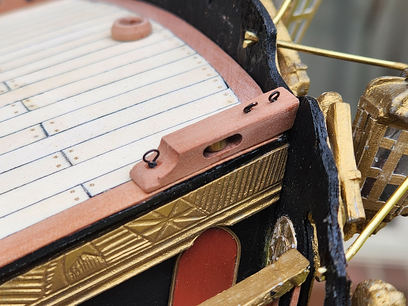
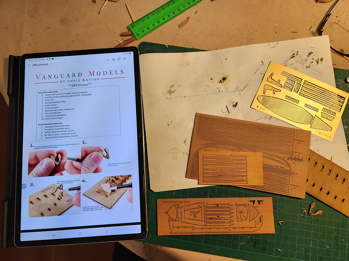
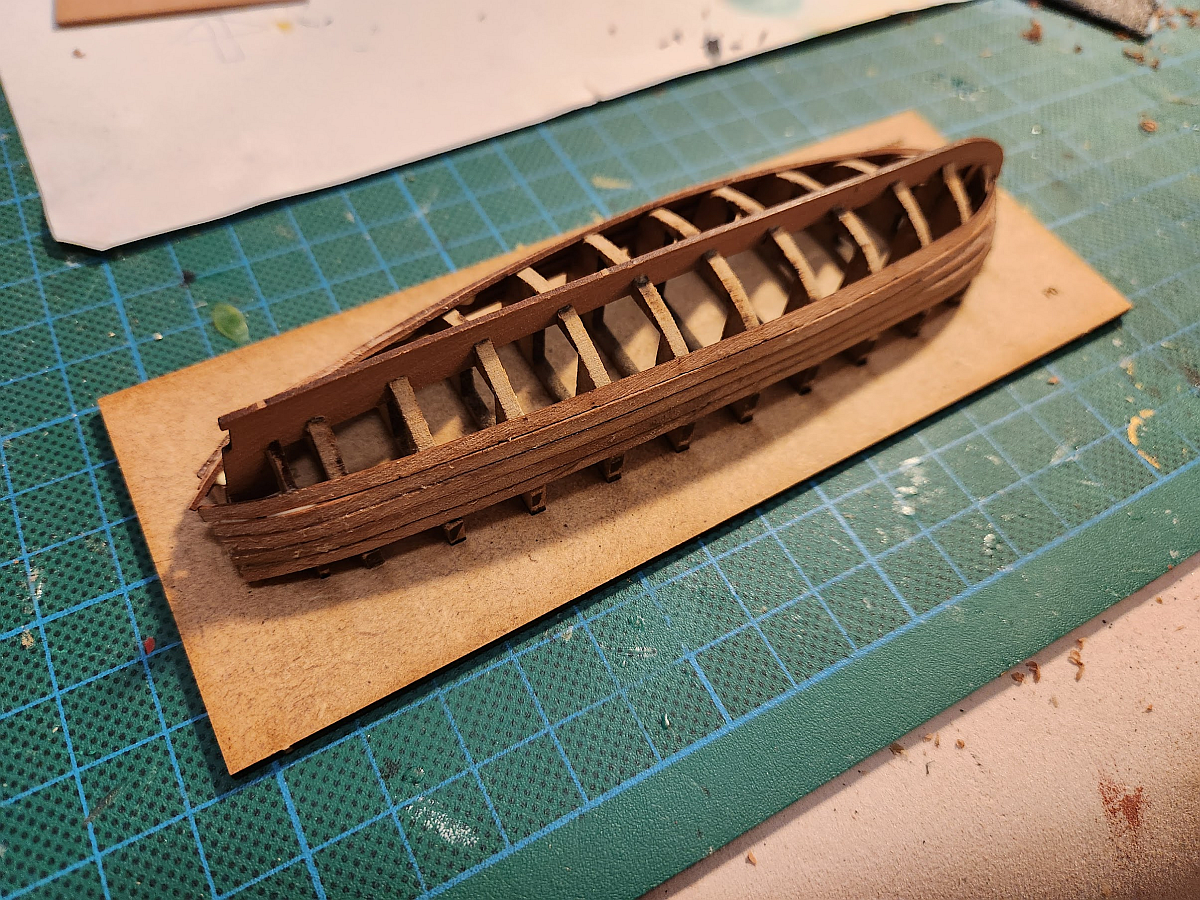
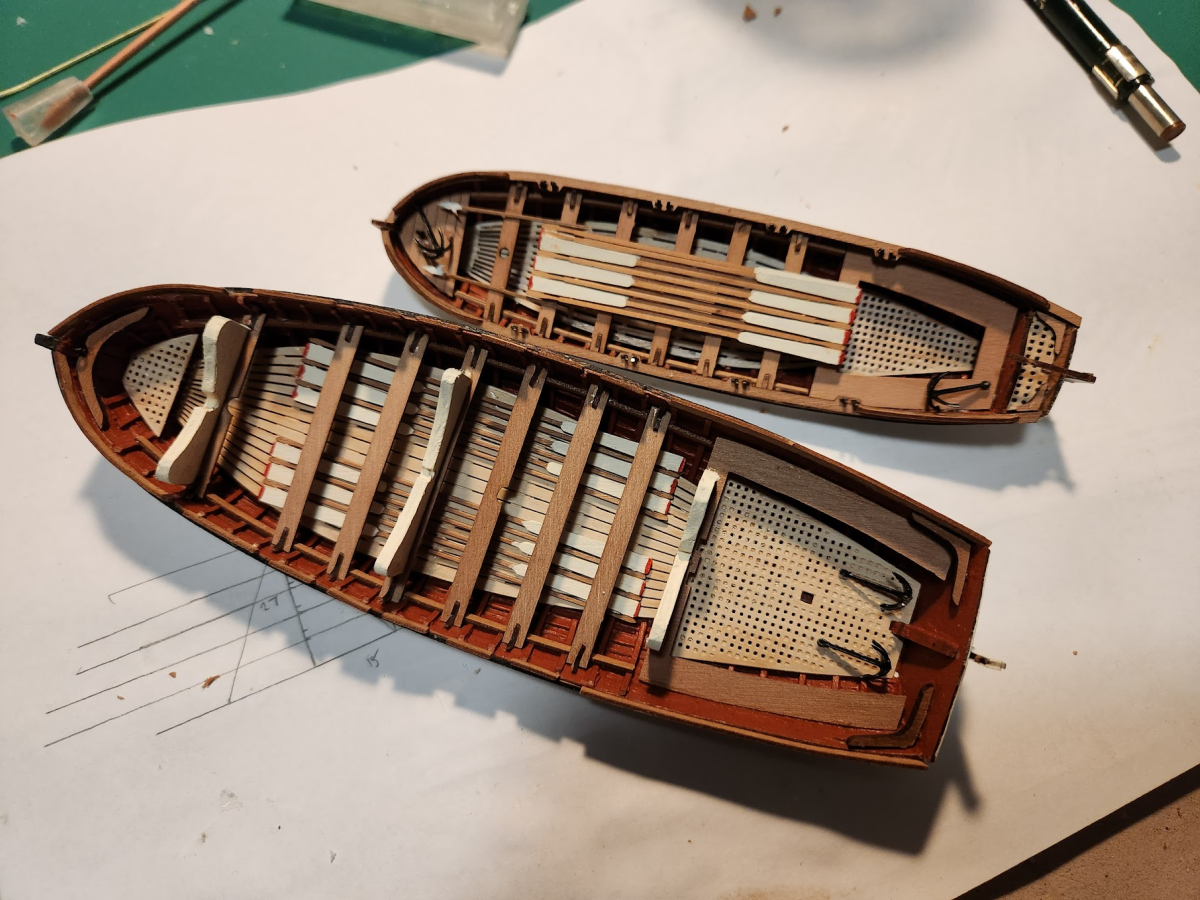
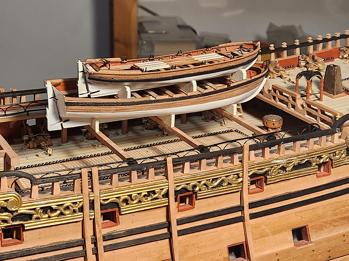
I also received something rather nice in the mail - a pair of ships boats from Vanguard Models. Chris Watton has a reputation as one of the best model ship designers in the world, and no wonder. These little marvels ticked all the boxes - reasonably priced, nice wood (pear), superb instructions, precisely cut parts, extra wood and spare parts in case you make mistakes and drop parts on the floor (where you will never find them again, these are TINY!), and fun to build. I honestly can not think of a way these little boat kits can be improved. Here is the one of the boats coming together: And both boats completed: You will notice that I deviated from Chris Watton's instructions and implemented my own colour scheme to match my ship. The bigger boat (34 foot launch) has supports for the 28 foot pinnace. Here are the boats mounted on the ship: The sharp eyed among you will notice the elaborate safety rail on the gangway. These were painstakingly soldered from brass wire and is more elaborate than depicted on any reference I can find. Those half circles really help with rigidity. I did not take any shots of the gangway rail under construction, but you can see some of it here. I am installing the outer rails. @piratepete007's Interpretive Info says that "most people" ignore the taper of the stanchions. Well, mine are perfectly tapered from 3mm in the base to 2mm at the top. What you need is a tilting table for your Byrnes Table Saw. I have one, but it is a complete pain to use because it is impossible to set up precisely. I had to estimate the angle, make a test cut, measure the angle, and repeat until I had the result that I wanted. Once enough stock for all the stanchions has been milled, individual stanchions can be cut out. Each alternate stanchion was pinned to the ship. Given that I have no training in engineering, I have a somewhat Victorian attitude to building. I over-engineer everything and make it as solid as possible. Very few things on this ship so far is in danger of breaking off, as proven when I had an accident where my ship rolled off my lap and crashed upside down on the floor while I was working on it. I inspected it for damage ... and ... nothing. NOTHING WAS BROKEN! A few loose parts had snapped off where I had designed them to fail (weak glue joints so that the glue joint fails rather than the part breaks). e.g. that poop deck breast rail in the post above is held on the ship with 3 tiny dabs of PVA glue. It simply separated at the glue joint rather than the part breaking.
-
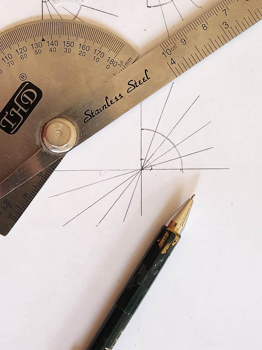
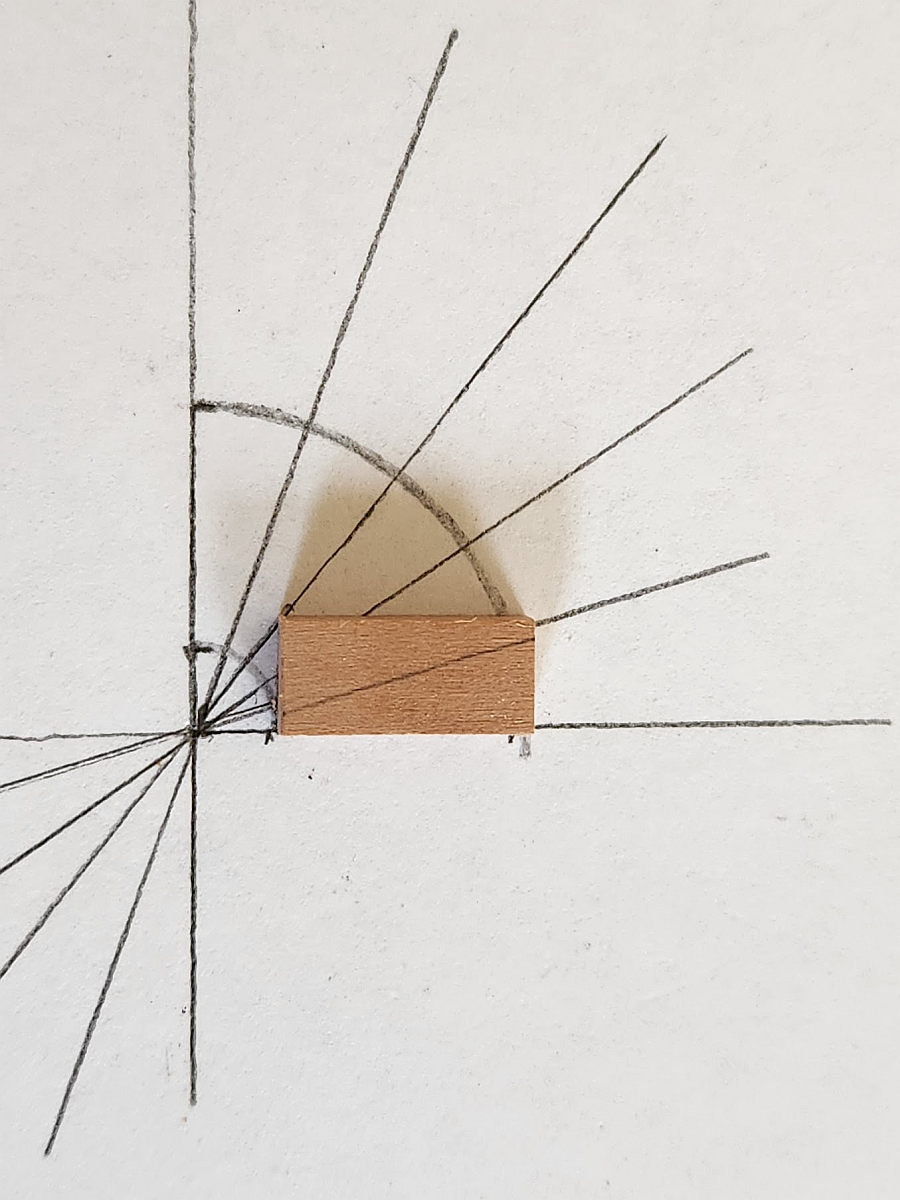
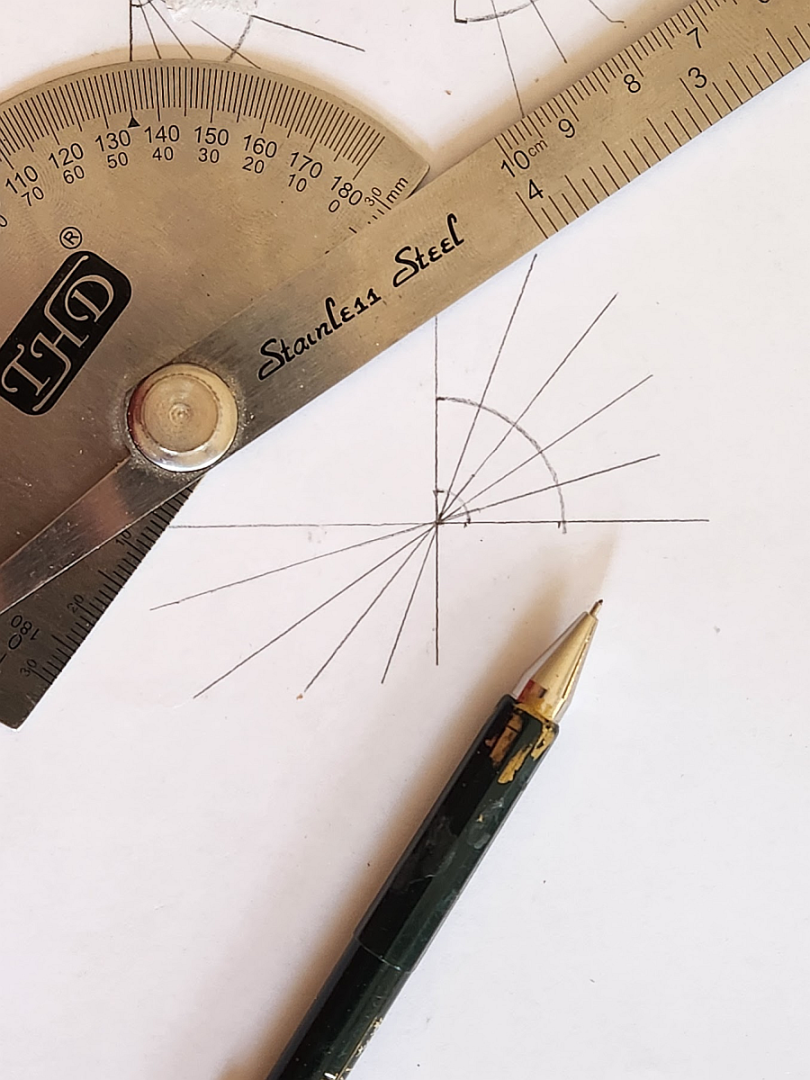
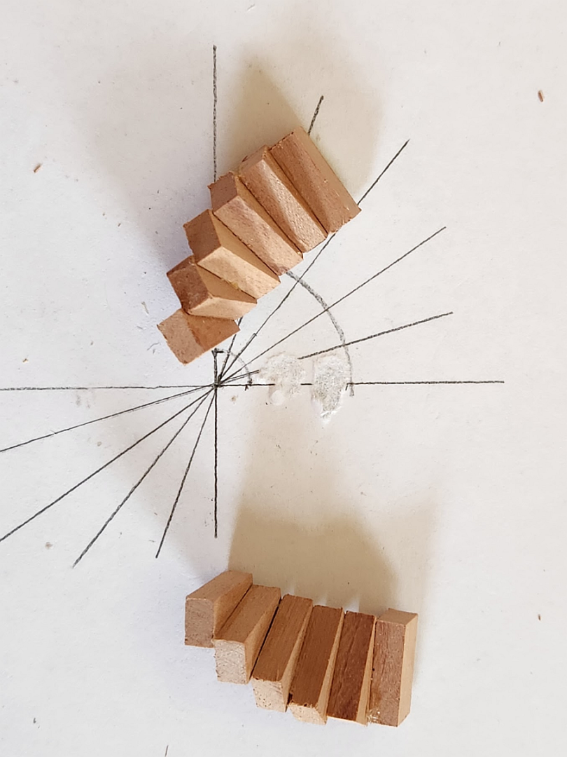
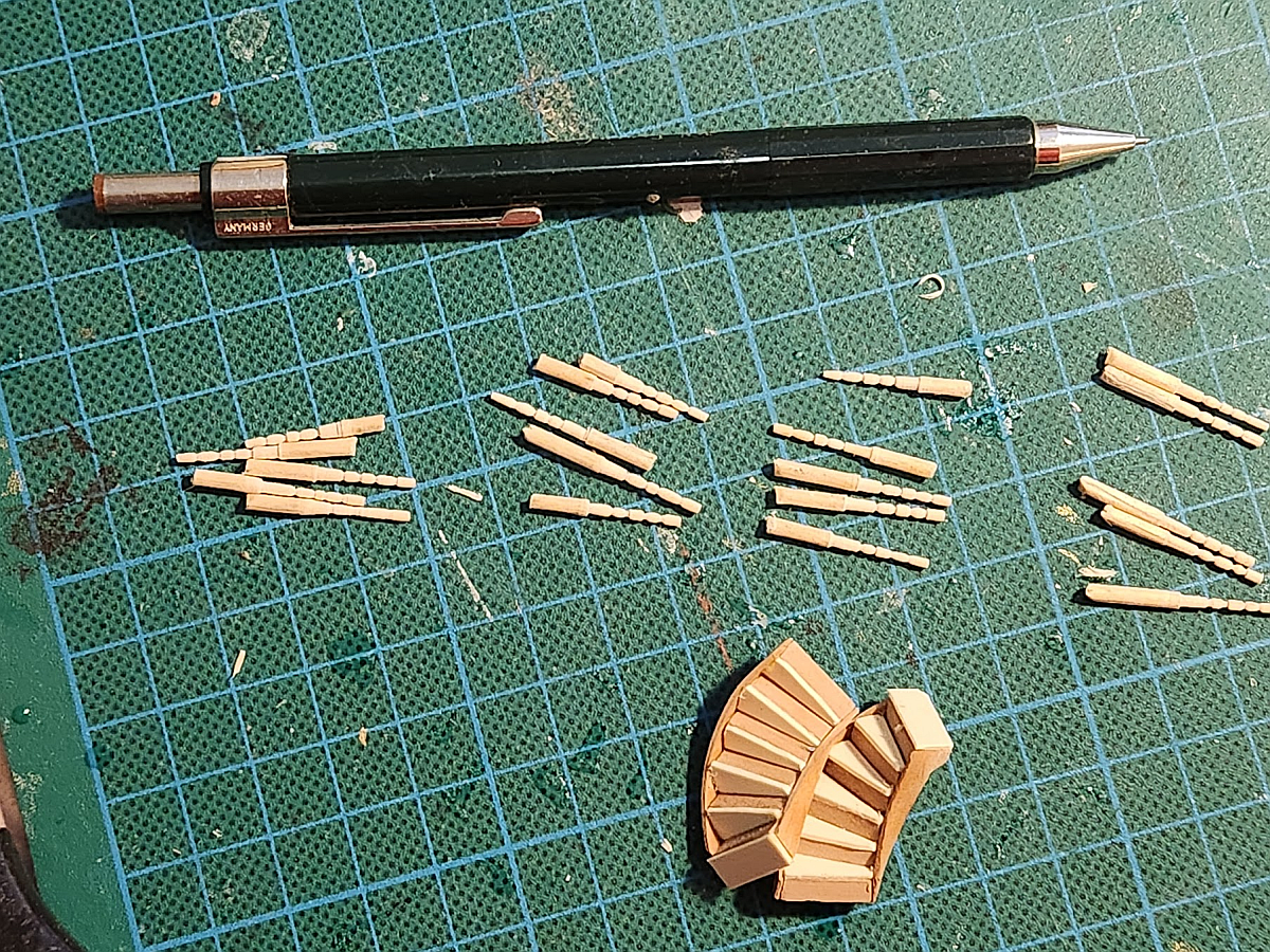
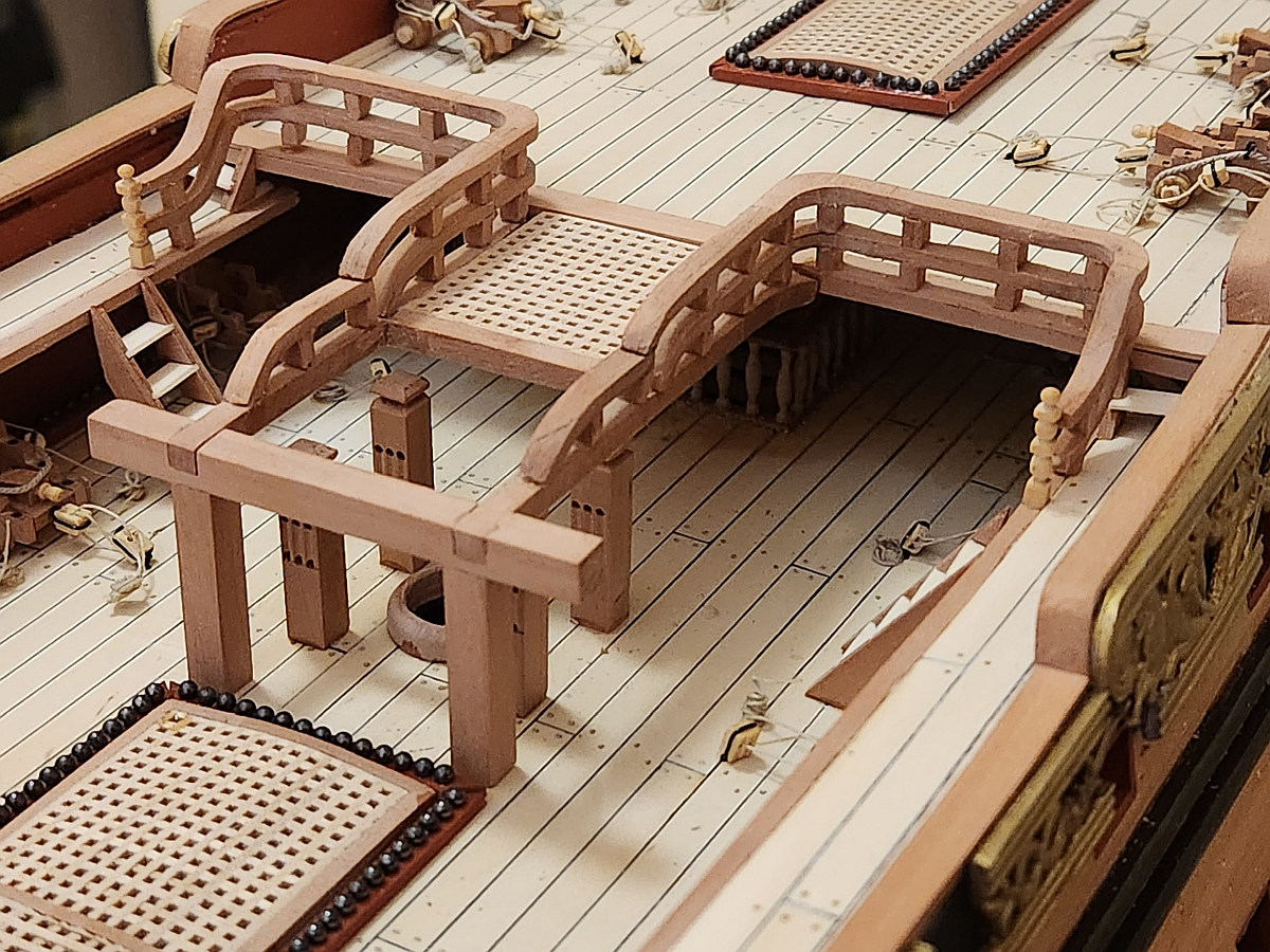
Well, my wife told me that even if nobody reads this build log, at least I will have a record of what I have been doing. There has been a LOT of work done to the ship now, to the extent that the hull is almost finished and I am starting on the masts. But I will share some progress pics. First is the poop deck rail. According to the plans this was elaborately decorated. Euromodel does not include this part in their kit, so I fabricated my own by carving it. I again used the same method of creating my own plywood out of laminated pear strips for strength and so that it won't fracture when I am carving the tiny fragile bits. Here is my laminated strip cut down to size with the lines marked with the aid of a pencil and a compass: And here is the completed deck rail compared to the plans: I used a tiny bit of creative license and made them close to what the plans suggested but not quite. Regardless, it looks beautiful on the ship. I also tackled the dreaded curved staircase. This is my method: first, calculate the angle required for the steps then draw it out on a piece of paper. I wanted 6 steps, so 90/5 = 18 degrees. These were accurately drawn out with a protractor: The first step is laid, and with the line for the next step is carefully marked out. Glue the next step up to the line, taking care to align the inside of the step with the inside curve. As the steps go up, it becomes more and more difficult to support the steps without them toppling over. I simply used more step offcuts to support the steps with the bottom step glued to the template to stop it from moving. Don't worry, once it's done just rip it off the paper and sand off the glue. It won't matter if it's ugly because it is on the bottom and won't be seen. Here are both steps complete: Now both steps can have stringers attached. I decided to add some holly planks to match the other steps. I turned 12 toothpicks for stanchions. And here is everything attached on the ship:

-
Well guys, it looks as if over the past few years MSW has changed. Plastic kit cars seem to get more interest than ship models. It takes time to write these posts, and it seems as if I am only talking to myself. I am signing out now. I will not post any more updates on MSW. I'll let you know when it's done, and that will be that.
-
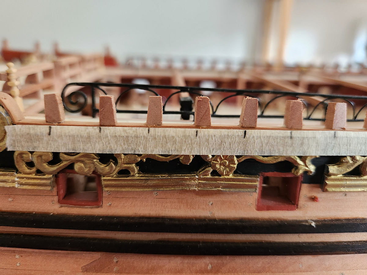
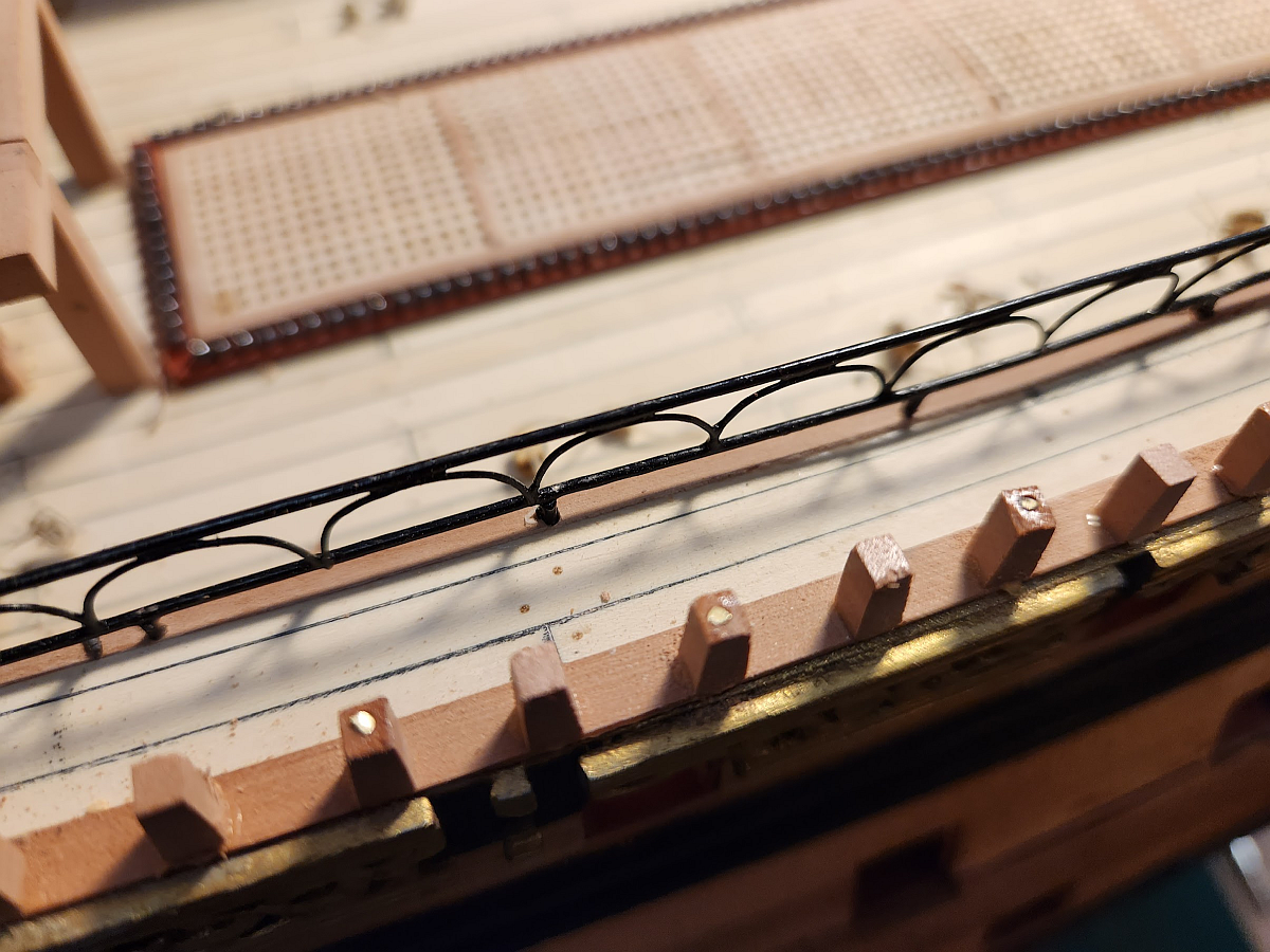
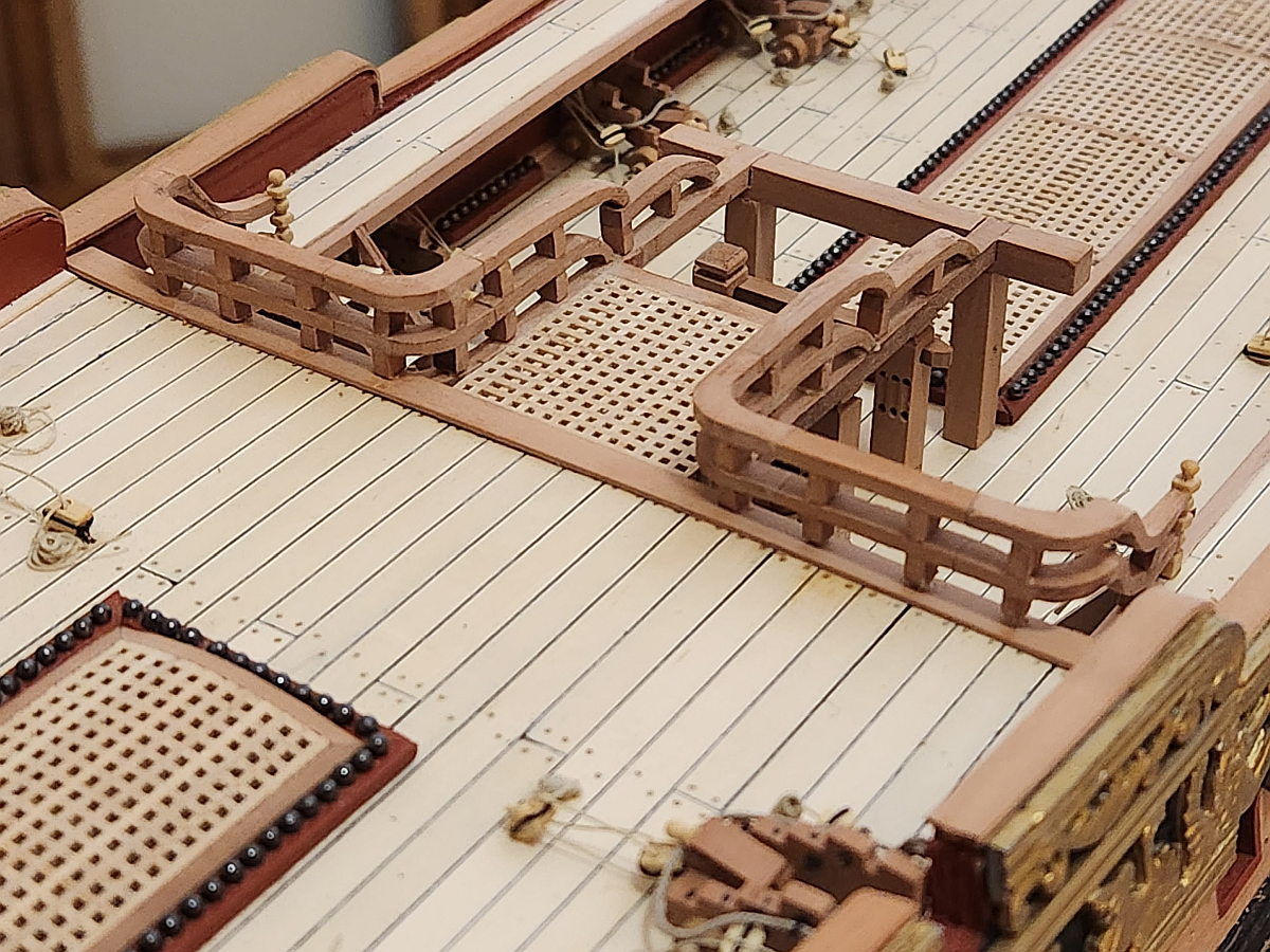
Work continues in the shipyard. The quarterdeck railings were devilishly difficult to make. The railings alone contain 40 parts (not counting the stanchions, of which there are 34). Of those 40 parts, 12 hard to be carved because it is simply not possible to bend wood like that. You will notice that I included the Newell posts (the turned stanchions at the ends of the railings at the top of the staircase). These were turned from a toothpick on a Dremel. I used needle files to shape them. The mast collar was made on my lathe. I don't know if Euromodel provided mast collars, I searched around in my parts and couldn't find any. So I made them. You will also notice that the gratings have a subtle curve. The cannonball channel was made on my Proxxon mill and IT TOOK FOREVER. The first problem was figuring out how to hold the workpiece down. I made a custom jig out of some spare plywood by using the mill to draw a straight line, then I glued two pieces of wood using the straight line as a guide. Then I used the mill again to square up the faces to make sure they were 100% parallel. A couple of self tapping screws held the workpiece down while I milled out the holes for the cannonballs. In the end I managed to get an excellent result.
-
HMS SUSSEX by KarenM - FINISHED - 1:48
Keith_W replied to KarenM's topic in - Build logs for subjects built 1501 - 1750
This is unbelievable! I just went through the whole build log. The result is truly amazing. It makes the rest of us look like amateurs by comparison. -
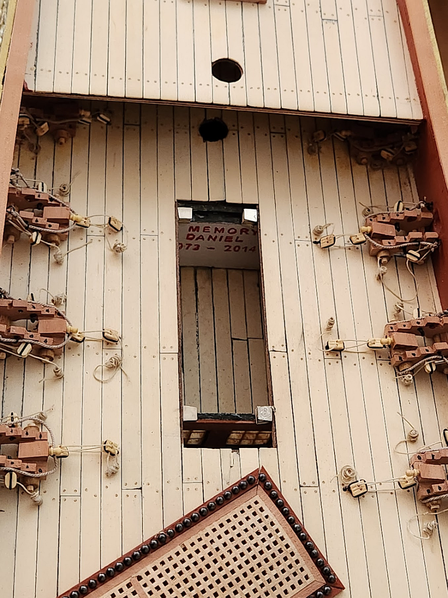
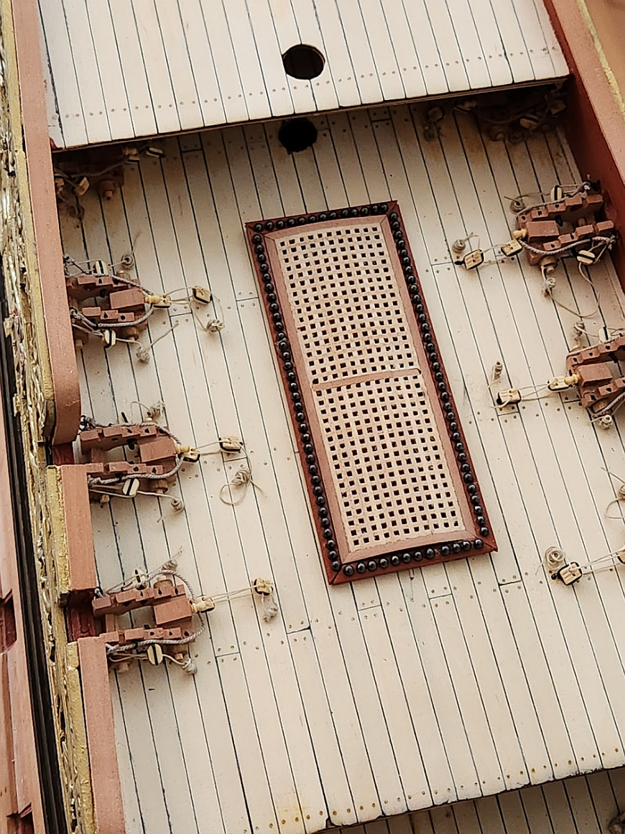
Many years ago, my friend passed away. He was only 41 years old. I was actually working on this ship when I received a phone call to tell me the terrible news. I painted a tribute to Daniel on one of the bulkheads: Over the years, the partially completed ship has been on display in my living room and I see that memorial every time I looked at the ship. I could not bear to cover it up forever, so I installed some magnets - those silver things on each corner of the hole. This way I can remove the grate and look at the memorial. Once the grate is installed, you would never suspect that it could be removed to reveal a hidden message inside.