


ccoyle
-
Posts
10,173 -
Joined
-
Last visited
Reputation Activity
-

 ccoyle got a reaction from Old Collingwood in Chevrolet C15a FFW by realworkingsailor - IBG Models - 1/35 - PLASTIC
I think you mean the 25 pdr? I did that one as a kid -- thinking about it made me realize how long some of the Tamiya kits have been around. 🤔
-
ccoyle got a reaction from Old Collingwood in Vought SB2U Vindicator by ccoyle - Kartonowa Kolekcja - 1/33 - CARD
Horizontal stabilizer added. The framing went together lickety-split, followed by some thin CA to stiffen the structure and a little sanding to get the outboard taper correct.
-
 ccoyle reacted to realworkingsailor in Chevrolet C15a FFW by realworkingsailor - IBG Models - 1/35 - PLASTIC
Thanks everyone!
To get my feet into this facet of the hobby, as well as get myself out of the summer doldrums, I picked up the Tamiya 15 pounder and Quad FGT kit. While this kit went together fairly well, and has reasonably good detail, the tooling is definitely showing its age! With a tooling date of 1974, there are plenty of mould seam lines and small amounts of flash all over.
It still builds up nice, and I would recommend it to anyone, as it is fairly inexpensive. I did add an an extra roof rack out of some styrene rod and I improved the grab handles by the roof hatch (I think they were stirrup steps from a 1/87th Tichy freight car kit I had leftover in the spares box). As the prototype Quad was build on the same chassis as the C15a, it should provide some interesting comparisons.
Anyway, it was enough kit to get me motivated and somewhat educated, so I'm not going into the C15 build completely ignorant.... I think....
Moving on with the main subject of this build log, the IBG instructions has the builder start off assembling a number of components that will be needed later on. There is definitely a generational shift between the IBG and Tamiya kits. Lots more parts, and much finer mouldings.
The results of a few days work!
The instructions start off with the wheels and tires:
Ok so far, not bad, decent introduction. There are locating pins, but they are not centred so the wheel halves can only go together one way. The tire branding and size is all clearly legible. Only a small cleanup to do around the joining seam.
Following the wheels, we jump to the rear buffer and tow hook assembly. Five separate parts in that little assemble. Ooo... this is going to be a slow build...
Then the two cab side steps:
One with a box, the other without. The one without I will eventually have to cobble together the cover for a little Johnson Chorehorse engine that was used to charge the radio batteries. On the hard body Wire-5 models, this auxiliary engine had its own little compartment, but on the canvas covers Wire-3, it sat on the front running board, hanging out in the open.
Then came the two fuel tanks, handed left and right, so be careful removing parts from the sprue. Do one at a time!
The transfer case. Interestingly, the Quad had an underslung PTO winch that ran off the same transfer case. The unused extra drive outlet for the C15a appears to have a grease cup in its place.
The Front bumper was next. The towing shackles are separate parts and we get our first taste of PE! The brush guard features PE braces on the rear. A small locating nub helps with their alignment.
The axles come next, starting with the front. 12 separate parts go into its assembly, and watch out as some of them are handed! The steering linkage needs to go on the shorter side. Also, move reasonably quickly into attaching the tie rod, as it will help ensure your front wheels are, at least, aligned. Doing this before the plastic cement has fully cured leaves enough play to get things looking right.
Now for the part that goes vroom! Six parts for the engine bloc alone, front, rear, sides, oil pan and head cover. This is one of those steps where the instructions could have been a little more helpful. The exploded cad drawing does little to advise the builder of the order in which the parts should be assembled. As it turned out, through dry-fit trial and error, it works if you join the front page and one side, followed by the back and then the remaining side. After that, the oil pan can be added, which should square everything up before adding the head cover. I have added the transmission, but I won't complete the engine assembly at this time. I have left a number of detail parts off to paint them separately.
So that's where things stand at the moment. This kit is way up there on the detail level. The fit of the parts is good, although the instructions are not the greatest, as I noted above. Some of the parts seem to suffer from an excess of sprue gates, so cleaning them up can be a bit of a chore. Also, there seems to be no sense in the part layout on the sprues. The front axle use parts off three different sprues, for example, and given the large number of sprues in the kit, it feels a little like 52-card pickup trying to to locate all the parts needed for the next step in the instructions!
Next up is some cab assembly, so there might be something vaguely truck-like for my next update.
Thanks, everyone for your likes!
Andy
-
ccoyle reacted to mrcc in Friesland 1663 by mrcc - Mamoli MV24 - 1:75
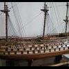
Here is some wider perspective shots should anyone be interested.
Deck fittings and railing is now done... which was easy work.
PS I had to cut some strip wood from some darker walnut stock I have in order to get all the deck fitting matching to a darker walnut
The last picture is the included boats with the kit. I will try and "pump" them up a bit but if that fails I reached out to Kolderstock models in Holland as they have a scaled replacement boat that looks very good!
I will be taking a little break now as I have a ton of fall yard work to do at this time and also to get ready for the winter tires on the vehicles.
Plus perhaps pay a little more attention to my wife 😊
-
ccoyle reacted to mrcc in Friesland 1663 by mrcc - Mamoli MV24 - 1:75
More details completed on the deck... first the railings and then the bits.
Materials are always tight with the old vinatge Mamoli kits.
I bought a used Proxxon saw and have started to put it to good use, specifically for the 2x3 strips.
-
ccoyle reacted to modeller_masa in Swift 1805 by modeller_masa - Artesania Latina - 1/50
I can't believe it! Based on your previous build logs and the expert skills you have demonstrated, you should have gained experience with many kits and met good friends. I'm checking every corner when I turn and polishing my tech one by one. I wish I'll be at the level someday.
-

 ccoyle got a reaction from modeller_masa in Swift 1805 by modeller_masa - Artesania Latina - 1/50
Your construction philosophy differs considerably from mine, which is "just wing that baby." Of course, my method doesn't always yield the best results. Hopefully your diligence will pay off!
-
ccoyle reacted to Claudius_Rex in Adventure by Claudius_Rex - Amati - 1:60 - Piriate Ship - First Build
@JacquesCousteau, noted! I think you're right. It's frustrating to have to start from scratch but I want to make sure I get every part of the planking process down with this first model. Thank you for your advice.
-
ccoyle reacted to CRI-CRI in Le Fleuron 1729 by CRI-CRI - scale 1/72 - French warship from Delacroix monograph
As planned, I copied on wood the decoration of the tympanum (a familiar organ for a musician...),
It's temporary, not glued, and depending on your opinion, I'll do the same for the balcony or not
In 1729, Rococo style arrived, following Baroque, with more intimate draw, based on arabesques :
-
ccoyle reacted to Glenn-UK in HMS Grecian 1812 by Glenn-UK - Vanguard Models - 1:64
It did not take too much effort to sand the hull smooth. I did a few trial fits of the second planking as I went along to make sure I was happy, especially with the termination of the planks with the stern post and stern counter.
Once that was done the keel outer patterns, stern post and outer stern counter pattern were glued in place, as can be seen below.
Next task was to add the ready to the second planking. With the planks laid out I did colour match as there is quite a bit a variation between the kit supplied planks. It not really an issue as the hull will be painted and copper plated.
The first two rows of planking have now been fitted to each side.
Close up of the bow area.
And now a close up of the right hand side stern area. I will need to add a small filler piece as indicated by the arrow.
And now a close up of the left hand side stern area, noting the small filler piece has been fitted.
-
ccoyle reacted to modeller_masa in Swift 1805 by modeller_masa - Artesania Latina - 1/50
Well... my rabbet and mortise doesn't work with this kit. 😪
I changed my plan and followed the AL manual.
4 belts x 4 planks
Looking good.
I used $9 mini iron only.
Garboard
First strake
Wale
Stealer
Half my work has been done!
-
ccoyle reacted to modeller_masa in Swift 1805 by modeller_masa - Artesania Latina - 1/50
I'm building a famous ship that has already been modeled many times. The 22110-N Swift kit is the cheapest intro line-up of the Artesania Latina. It is a two-masted schooner with simplified details, and has been renewed several times for 50 years. There are tons of American schooner kits with better details in the market.
This post won't be a tutorial-like build log. I'm studying my building technique. I hope you skim my post quickly, and I'll be much obliged if you find any interesting point.
3-Dimentional error checking
Fixing errors
Plank battens
This is a small ship.
Temporary planks are done.
The end of hull framing.
-
ccoyle reacted to Chuck in Syren Ship Model Company News, Updates and Info.....(part 2)
Just an FYI guys...
Many of you have noticed that the store is shut down for maintenance. I am actually recovering from a bad flu that really knocked me on my butt. I am gonna need a few more days to get over this one. I will reopen as soon as I can get some of my energy back. This one really knocked me out. I am out of bed today so its progress.
Chuck
-
ccoyle reacted to Chuck in Syren Ship Model Company News, Updates and Info.....(part 2)
Todays shop critters…its hard getting used to being out of metropolis. Too many critters out here. Dinosaurs!!!
-
ccoyle reacted to EricWiberg in Soleil Royal by EricWiberg - Heller - 1/100 - PLASTIC - started 45 years ago
And the dolphin hance pieces are 95% completed... I am carefully configuring the railing to the contour of each dolphin. I have an idea for a subtle cradle that the dolphin will nestle into, simply using several thin half-round Evergreen strips. The dolphin is not tight fitted in.
I still have a little bit of finishing work to do.. very subtle things like the eye is too round, as in the lower right dolphin.
I wasnlt satisfied with making eyes from ApoxieSculpt... the eyes were just tiny little balls that I couldn't get right. I rummaged in my shotgun reloading supplies and pulled out some #9 pellets, which happen to be 0.08" diameter. Still too big and round, but I popped each pellet into a vise and then sawed a cut into each pellet. I then split each pellet in half... lead is soft.
I didn't like the round eyes... what to do? I sliced with am Xacto knife and made a different eye shape that - hopefully - looks a little meaner with an ApoxieSculpt brow. Marc LaGaurdia has observed that statue work like these almost bordered on the grotesque side, exaggerated like gargoyles.
-
 ccoyle got a reaction from realworkingsailor in Vought SB2U Vindicator by ccoyle - Kartonowa Kolekcja - 1/33 - CARD
Horizontal stabilizer added. The framing went together lickety-split, followed by some thin CA to stiffen the structure and a little sanding to get the outboard taper correct.
-
 ccoyle got a reaction from Canute in V108 by catopower - Digital Navy - 1/200 Scale - CARD - Torpedo Boat - MSW Tutorial Build
Of course I would be interested, but interested enough to open the padlock on my wallet? That's another question. Of course, there's always Christmas and birthdays. 🙂
If I were interested, I'd want to get the kit and all of its available after-market accessories.
-
 ccoyle got a reaction from GrandpaPhil in Vought SB2U Vindicator by ccoyle - Kartonowa Kolekcja - 1/33 - CARD
Horizontal stabilizer added. The framing went together lickety-split, followed by some thin CA to stiffen the structure and a little sanding to get the outboard taper correct.
-
ccoyle got a reaction from Canute in Vought SB2U Vindicator by ccoyle - Kartonowa Kolekcja - 1/33 - CARD
Horizontal stabilizer added. The framing went together lickety-split, followed by some thin CA to stiffen the structure and a little sanding to get the outboard taper correct.
-
 ccoyle got a reaction from yvesvidal in Vought SB2U Vindicator by ccoyle - Kartonowa Kolekcja - 1/33 - CARD
Horizontal stabilizer added. The framing went together lickety-split, followed by some thin CA to stiffen the structure and a little sanding to get the outboard taper correct.
-
 ccoyle got a reaction from BLACK VIKING in Vought SB2U Vindicator by ccoyle - Kartonowa Kolekcja - 1/33 - CARD
Horizontal stabilizer added. The framing went together lickety-split, followed by some thin CA to stiffen the structure and a little sanding to get the outboard taper correct.
-
ccoyle reacted to RGL in Renault FT-17 on a Renault FP artillery transporter by RGL - Meng/U-Models - PLASTIC/RESIN - diorama
Ok, got distracted by a little side project
-
ccoyle reacted to Valeriy V in Libertad 1925 by Valeriy V - Scale 1:100 - Spanish Type F Light Cruiser
Frame sheathing.
-
ccoyle reacted to Keith Black in Sternwheeler From the Susquehanna River's Hard Coal Navy by Keith Black - 1:120 Scale
Thank you for the likes and the kind comments.
I'm inching ever closer to the finish as I got the hog chains (such as they are) made and attached.
Added some weathering
The post that the hog chain rod passes through are 0.20 inches high and the hole is 0.15 inches high from the deck. The post are a little wider than I wanted but I needed the extra gluing surface,
That is one mighty turnbuckle but looking at the original photo below the arrow points to the turnbuckle end level with the water line.
Thank you for your support and for being part of the journey.
Keith
-
ccoyle reacted to Keith Black in Sternwheeler From the Susquehanna River's Hard Coal Navy by Keith Black - 1:120 Scale
Thank you for the comments and the likes.
I got the steam whistle line brace made and attached to the exhaust line. I couldn't connect the brace to the pilothouse wall as there just isn't enough room in that space to work and make a successful connection to the wall and lines. The distance between the steam whistle line and the exhaust line is 0.20 inches. I had to keep the brace higher than I wanted because I needed to get the jewelry plier jaws between the lines to work making the brace. It was fiddly delicate work, hopefully I learned a lesson and won't get ahead of myself in the future.
The brace is made from a single piece of PE brass 0.011 inches thick and 0.042 inches wide looped around the lines with the ends meeting in the middle between the two lines and held together with CA.
It looks okayish and I'm happy it's done. Back on schedule.
Thank you to each of you for your support.
Keith