


Cathead
-
Posts
3,552 -
Joined
-
Last visited
Content Type
Profiles
Forums
Gallery
Events
Everything posted by Cathead
-
¡Bienvenida a nuestra comunidad, Sergio! Please start a separate build log where you can share your pictures, and tell us here when you've done so. I hope you continue to enjoy this really fun hobby.
-
 Looks like a fun project, keep us updated.
 -
Your progress looks great so far. I love the look of these vessels. Hope you'll keep posting on your progress.
-
Chances are you'll be happier in the long run if you start with something simpler. Even a basic open boat will teach you a lot about the skills needed to do a more complicated model and won't take you long enough to meaningfully delay your dream project. Way too many people dive in over their heads and get disillusioned. Wooden ship building is not like assembling a plastic kit by just gluing the pieces together in order; there are a lot of new skills you will have to learn, and doing that the hard way on your expensive dream kit is asking for trouble.
-
I was talking about this with Mrs. Cathead over dinner and she reminded me of something relevant. The last time we visited the Bertrand Museum, which has a huge and beautiful model of that vessel, I found a number of inconsistencies (at least, as far as I could tell) between the model and the plans/descriptions published in the book written by the archeologists who excavated and documented it. None of these detracted from the overall impact of the model on viewers wanting to understand what these complex vessels looked like overall, though it would be really interesting to talk to the original builder about various design choices given the information available.
- 599 replies
-
- 7
-

-
- sidewheeler
- arabia
- (and 4 more)
-
Bob, I'm grateful for your feedback. I hope I'll always be open to constructive criticism and the opportunity to learn more. Regarding the masking tape, I'm hoping that the combination of wood glue below and paint above will seal it in pretty well. When building models, I get a lot of satisfaction from making do with what I have on hand; I don't like keeping or purchasing a large stock of specialty items. It's a personality trait that one could argue holds me back from making higher-quality models, but it improves my enjoyment of the work. I can see how it might be frustrating or worrying to wonder whether that degrades the longevity or value of a model like this. I'll certainly keep your concern in mind for future reference, but it's far too late now for this model! I used masking tape without glue on my Bertrand; that model is now four years old, displayed under fairly variable temperature conditions, and showing no signs of concern (I realize the hopeful life of a good model is much longer than that). So crossed fingers, I guess. Regarding the "tarpaper", thanks for the interesting history. I was apparently remiss in thinking that it was ok to follow the Chaperon's style for this vessel. My other references (like Hunter, Kane, and Bates) don't provide clear details on roof/deck coverings, especially for early boats like this. I suppose it would have been better to ask early and wait for advice, but I was excited to keep going and it never occurred to me to investigate further. That being said, I think one can squint and decide that the current look could also simulate canvas? My strips are narrower, closer to 2.5' than 4', and they show up more than your suggestion for canvas's appearance, but it at least conveys the idea that these upper surfaces were treated differently than the lower decks by covering with some form of water-resistant roll. Regarding the color, I can try a new coat of lighter pastel to shift the tone a bit more toward true grey. Especially with western riverboats, there's always the escape valve that there were few standards and lots of eccentric innovation, so maybe Arabia's owners got their hands on some unusually narrow canvas for a bargain price and skimped on the white paint in the color mix as well. After all, we have no idea what it actually looked like above the main deck, so there's a ton of conjecture in this model already. Overall, trying to keep up with the details necessary to make a truly accurate period model gets overwhelming. It can even be off-putting. I can point to a variety of other things on this model that I know are less than ideal, and that an expert would almost certainly notice (in terms of both accuracy and modelling quality). This model will win no awards at any model show based on the judging criteria as I understand them. These came either from my own mistakes, a lack of sufficient knowledge, or from compromises to keeping the building process fun and not exhausting (sometimes all!). I will have to chalk the roof covering up to that as well. The good news, for me as for most of us, is that the vast majority of viewers will never know the difference. I hate to put it that way because accuracy is reasonably important to me, but it's also a coping mechanism to stay sane. I just don't have the time or resources to become a true expert, not at age 40 and with many other interests. Even were this to be displayed in a museum somewhere someday, it's close enough to inspire most viewers to a reasonably accurate understanding of the vessel. However, every model I built teaches me more and lets me build a better one next time, particularly with the advice and feedback from folks like yourself. Thank you.
- 599 replies
-
- 13
-
-
- sidewheeler
- arabia
- (and 4 more)
-
That's a fantastic idea! I've been playing around with the idea of various smaller Missouri River steamers for a future build. One of my motivations for doing the Arabia was just as you say, surprise that such an otherwise excellent museum had no way to visualize the craft in three dimensions other than a painting. I, too, am a lifelong history buff and think there's a major niche for using models to educate people about inland watercraft (not just sexy sailing ships).
- 133 replies
-
- 5
-
-
- chaperon
- model shipways
- (and 2 more)
-
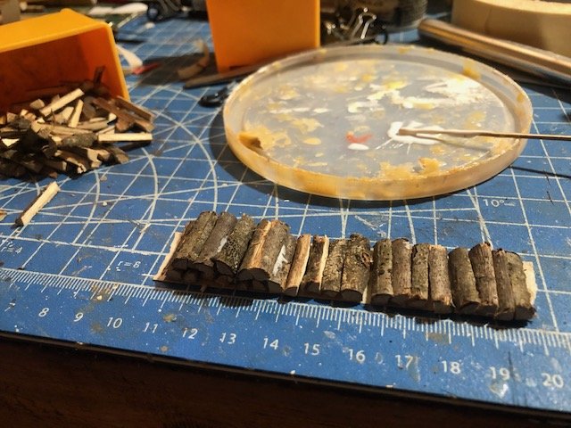
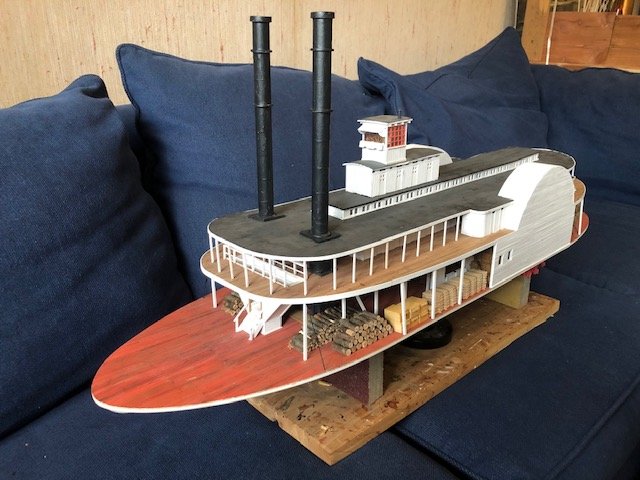
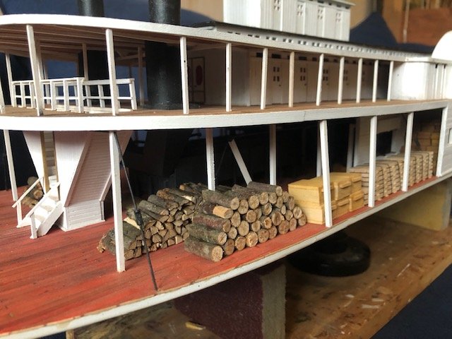
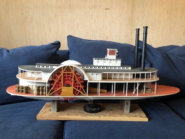
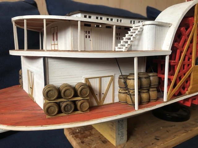
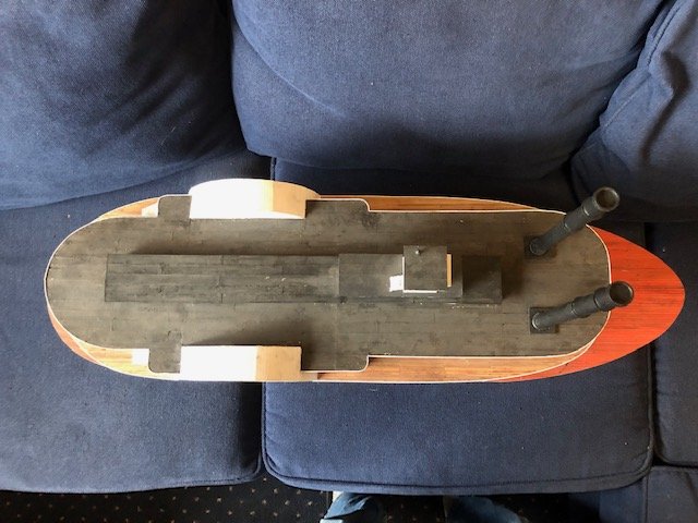
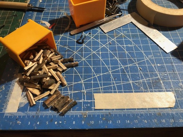
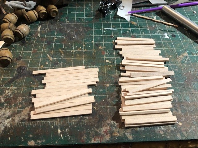
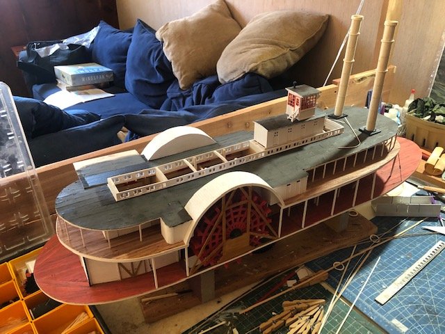
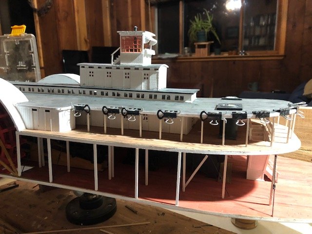
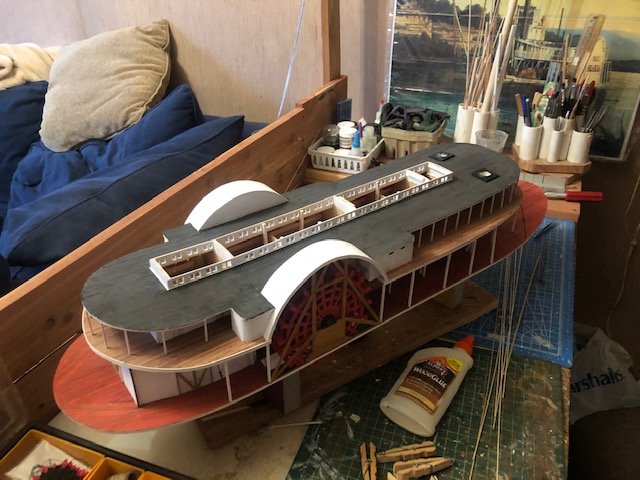
I decided I needed to start fillling in details before the final railing and other things get installed. Also, this felt like a really nice shift from the endless superstructure work. First up, firewood piles. Nothing innovative here. I laid strips of double-sided tape, cut & split lots of branches collected from the outdoors, and stacked them with liberal applications of glue. Final product will be shown soon. Next, I made stacks of lumber by milling scrap wood on my Byrnes table saw. I stacked these and glued them together with spacers, then wrapped thread to simulate tie-downs. I also made some crates from scrap wood. Here's a view of the cargo along the port side: I left one stack of wood unsplit to simulate recently cut wood. Next, I dealt with the large stack of barrels I ordered from Model Expo. These are turned from wood, and I used a black marker to carefully darken their hoops. I set these up in two ways for visual interest, both of which I've seen used in contemporary photos (either horizontal or vertical): They don't show up well, but I made tie-downs for the horizontal barrel stacks. I should have for the vertical stacks but didn't think of it until they were already installed. Didn't take photos of the process, but I think these are pretty self-evident. Also note that you can see the final wood strips covering the edges of the boiler and hurricane decks, as well as the staircases up to the hurricane deck that are now installed (I think I described making these in an earlier installation before setting them aside). So here are some overall views of the model as it now stands. The chimneys are painted and I think look really nice. The darker black contrasts will with the softer decks and helps make them look more metal. They're not permanently installed and won't be for a while yet. Note that I put almost no cargo on the starboard side; that's because I want the interior view to be fully open. I made a small firewood pile near the bow, parallel with that on the port side, so it looks more symmetrical when viewed from the front. Adding the cargo really changed my sense of this project. It suddenly feels near completion, though that's an illusion given how much there is left to do. But it really looks like a steamboat now. Just going to add that I'm thinking about all my fellow modellers out there in the world under the current pandemic situation. Our hobby trends toward the higher-risk population and I hope we can suppress and manage this thing to the best of our abilities. I'm very fortunate to have a life/work situation that keeps me pretty isolated and independent, but have aging parents and parents-in-law that are at higher risk but I can do little to help. Thanks for reading, hope this log adds a smile to your day.
- 599 replies
-
- 18
-
-
- sidewheeler
- arabia
- (and 4 more)
-
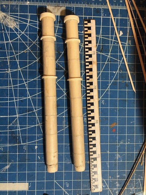
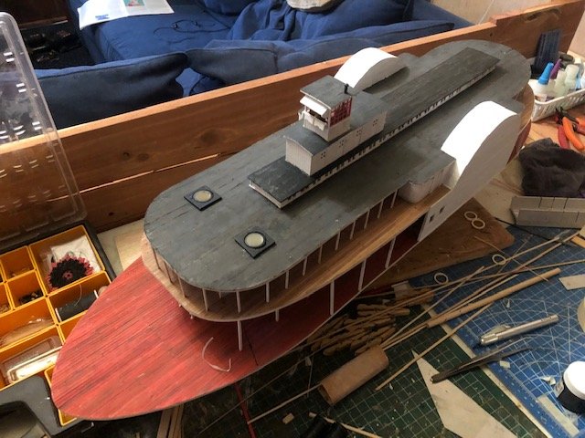
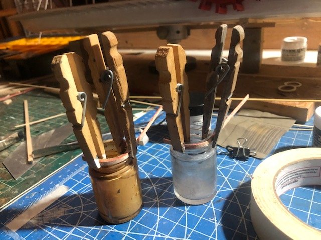
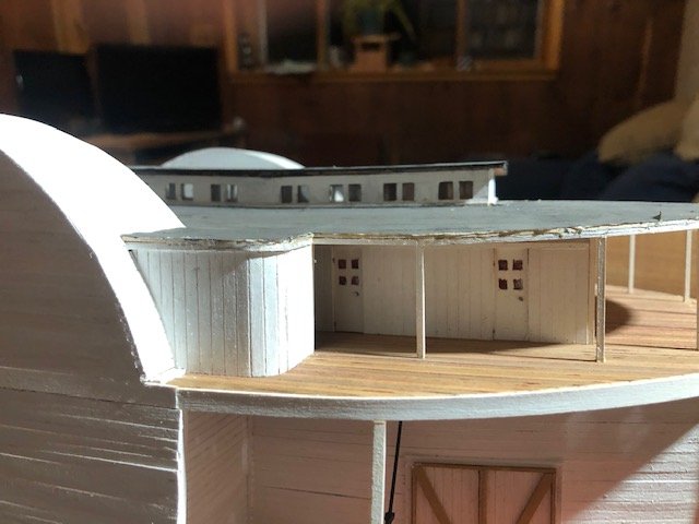
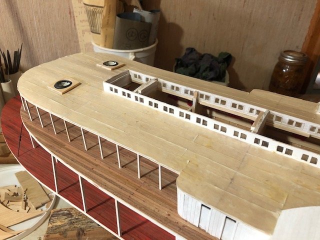
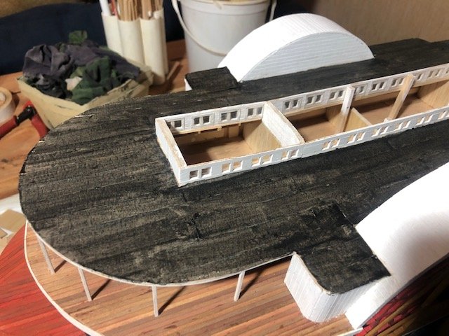
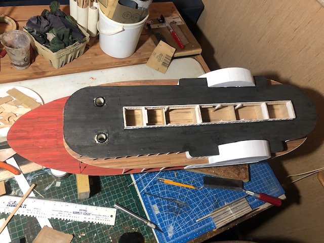
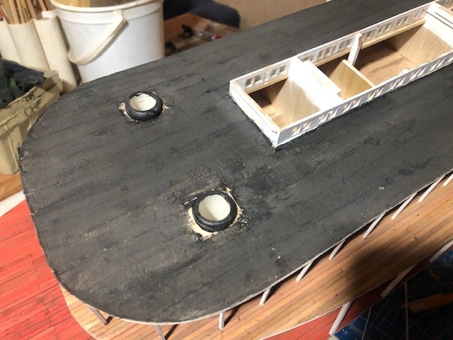
Roger, sure, I'd love to see it. That's very kind of you. Lots of progress over a quiet weekend, so much so that I'll break this update into two posts. First, more superstructure work. I built the chimneys from two wooden dowels covered in rings of masking tape using the same method as the upper decks. I rotated the seam 90° for each strip. I made wider rings by cutting hoops from scrap PVC fittings that had the right inner diameter to slide over the dowels: Next I framed in the roof of the hurricane deck skylight, covered it, tarpapered it, and painted it. In the last photo below, you can see how much darker the painted surface is pre-pastel (compare to the rest of the hurrican deck). I really like how the pastels soften the color and texture. Then I shaped and painted strips to run around the edges of the boiler and hurricane decks to hide the planking edges. These involved making some very tight curves, especially around the heads. Before: After/during: Once these were in place I changed focus and starting making some cargo details for the main deck.
- 599 replies
-
- 12
-
-
- sidewheeler
- arabia
- (and 4 more)
-
I suspect tie-downs matched the "whatever the builder/operator wanted" theme. I've also seen evidence of metal rods (like hog chains) and metal straps. Yours look great!
- 133 replies
-
- 3
-
-
- chaperon
- model shipways
- (and 2 more)
-
HMS Beagle by Luekutus - OcCre
Cathead replied to Luekutus's topic in - Kit build logs for subjects built from 1801 - 1850
Great choice of project! As an earth scientist and naturalist, I've read the accounts of Darwin's voyage several times and a model of the Beagle is on my life list. I'll be quite interested in following along with your build. I was in Chile in 2018, including a visit to the Nao Victoria museum in Punta Arenas, Patagonia, which includes a full-scale replica of the Beagle. See this post and the next one in my Chile thread for a series of photos; I can provide more if you're looking for details of a given area. Here's one photo for inspiration: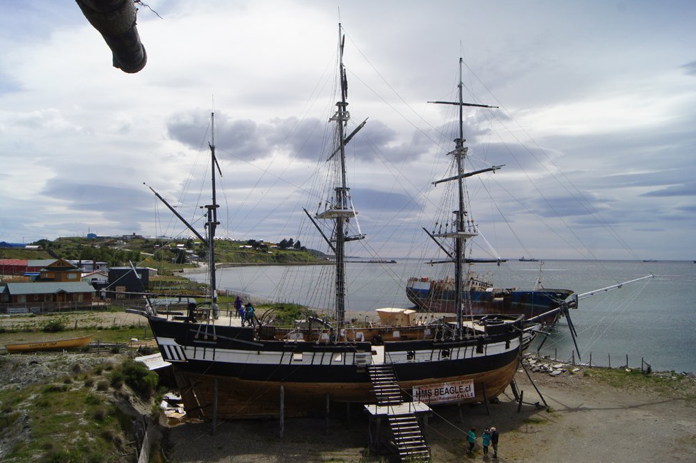
-
Good question about pilot house tiedowns. These boats were often flimsiliy built and quite susceptible to high winds. This would be especially true for boats heading into the western Plains (e.g., up the Missouri), but severe storms could be encountered anywhere in the Mississippi drainage and the pilothouse is a high and vulnerable structure, often being 40-50 feet above water level where winds are quite a bit stronger (for example, a quick search for wind turbine design specs suggests that winds at 30' can be 1.5 times those at ground level and continue to rise with height). Also, even larger river valleys can funnel winds; the lower Missouri River valley is routinely far windier than the surrounding landscape despite being over a mile wide between bluffs several hundred feet high. Whereas further upriver, as the timber grew smaller and scarcer, the pilothouse could be the tallest thing for miles except the chimneys. I suppose the use or not depending on the quality of construction, owner's preference, and so on. From my reading, numerous boats were damaged or destroyed by storms. Think of the pilothouse like a little garden shed easily tipped over by strong winds. The Arabia's pilothouse is 35-45 feet above water level, roughly equivalent to the third or fourth storey of a building, and I suspect Chaperon is similar. So put that little garden shed on the roof of a 3-4 storey building and consider how much wind load it's recieving. Obviously it's structurally tied into the lower superstructure, but if you were up there in a cheap, lightweight pine box during a windy day (much less a real storm), how secure would you feel? As you noted, it's not the vessel's speed that's important (as this was usually fairly low), it's the atmosphere around it. Again, good question, it's all the little details that make this so much fun to learn about. And all of the above is just my amateur opinion.
- 133 replies
-
- 3
-
-
- chaperon
- model shipways
- (and 2 more)
-
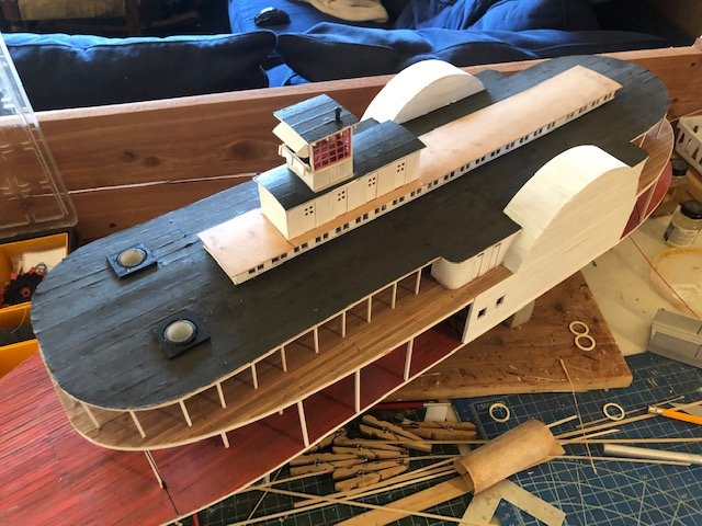
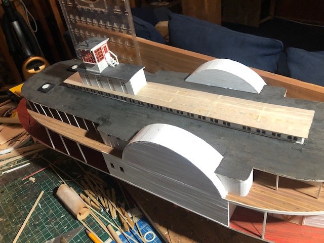
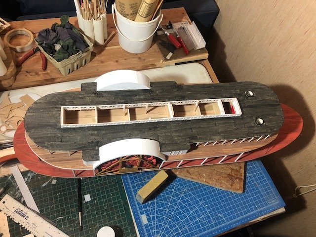
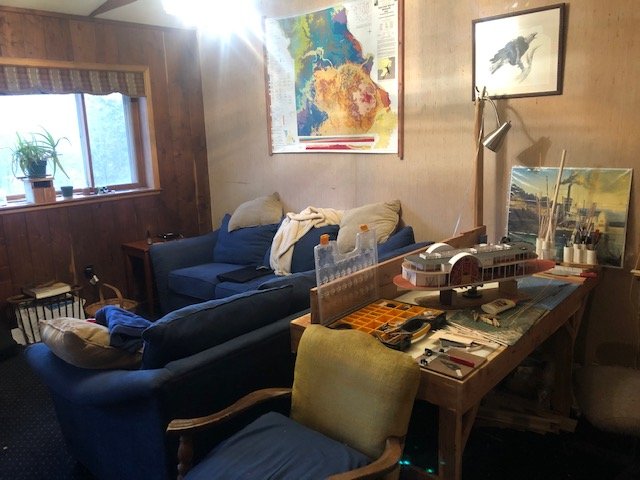
Finished the hurricane deck! Full masking-tape tarpaper prior to painting: After a coat of thinned black paint as a base layer After rubbing on dark pastel powder to soften the texture: I added some moulding along the skylights to hide the joints, and will likely to the same around the wheelboxes. In separate project, we rearranged our living room, allowing the model desk to rotate 90°. It used to face the wall with my back to the room, which I never liked. Now it faces into the rest of the room with a nice view out the window, which is much more pleasant. So this is where the magic happens... I'm starting to think about railings for the boiler deck. Handmaking all those railings won't be fun and I want to come up with a way that won't drive me crazy but still look ok. Thanks for reading
- 599 replies
-
- 17
-
-
- sidewheeler
- arabia
- (and 4 more)
-
Nice! The stained railing cap is a neat touch that helps make the model your own.
- 133 replies
-
- 1
-
-
- chaperon
- model shipways
- (and 2 more)
-
It's neat to see the fun those kids are having. I still have family in Luzon.
-
Cool! My mother grew up in Cebu and Mindanao. What brought you there with an RC boat?
-
2020 NRG Conference
Cathead replied to kurtvd19's topic in NAUTICAL RESEARCH GUILD - News & Information
This is really exciting. Mrs. Cathead and I love the Channel Islands and have done some great multi-day hiking there in the past. We're strongly considering attending this year and combining the conference with a lots of time out on the islands. Also falls pretty close to our anniversary, all the better. -
Bob, good eye and good question. Just a personal preference. I think I used a very small overlap when I did the roofing of the Texas and pilothouse, but here decided to lay it flat. Kurt's way is probably more realistic given that there would need to be sealed seams. However, the longitudinal seams would need to be carefully placed so that they shed water downslope (like shingles on a roof). On my hurricane deck, I really wanted to work from the inside out to ensure a good fit (easier to trim at the outer edges of the deck than in a central strip), which meant that overlapping seams would be facing the wrong way. I don't think the effect will be very noticeable either way, though I supposed at the Chaperon's large scale (1:48 instead of my 1:64) it would be that much more noticeable. Again, wouldn't hurt to test both ways on scrap and see which you like better.
- 599 replies
-
- 6
-
-
- sidewheeler
- arabia
- (and 4 more)
-
Bob, I'd definitely recommend testing the method off-model first, to figure out the quirks. One thing to consider is that too much paint can loosen the glue, especially at the corners and edges, making annoying curls. That's one reason I like to finish with pastels, so I'm not tempted to overpaint. Of course, a few imperfections just help with the hard-used working boat effect. I bet the real tarpaper got scuffed and torn. I hope it works for you and will be interested to hear about your experience.
- 599 replies
-
- 5
-
-
- sidewheeler
- arabia
- (and 4 more)
-
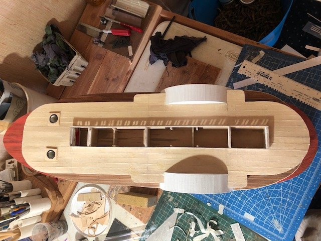
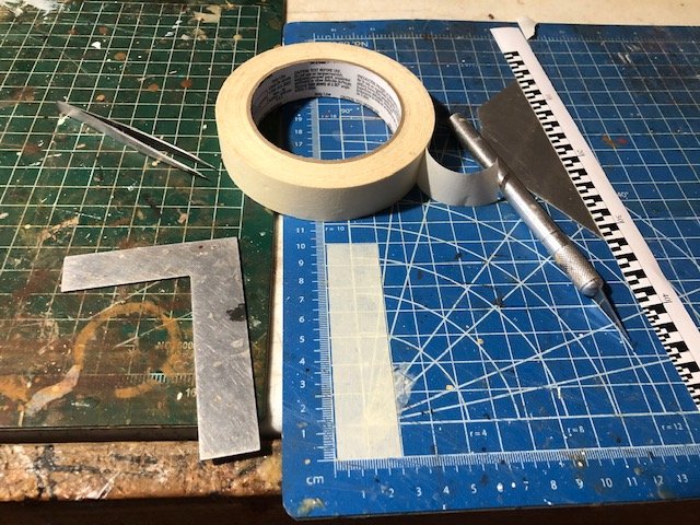
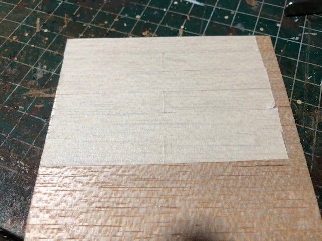
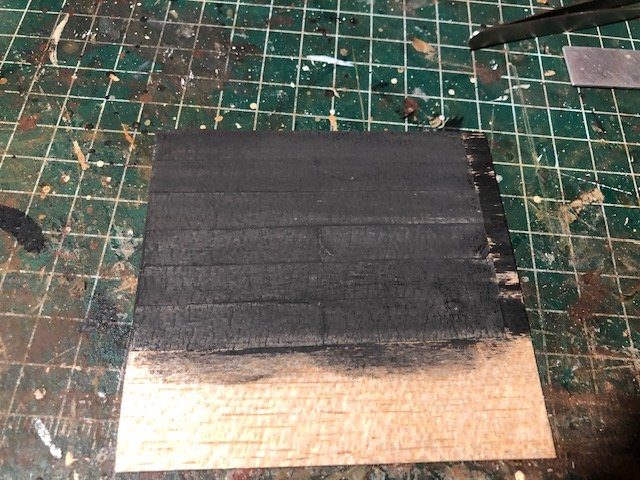
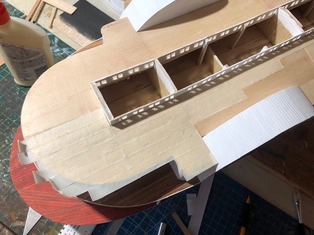
The last three weeks have been very stressful and time-consuming for a bunch of reasons I don't need to go into here. This morning was the first time I've felt focused and sane enough to return to the model. The next step involves laying out the tarpaper covering of the hurricane deck. Kurt's digital book on building the Chaperon has some very good advice for simulating this material (see p. 55 and onward), but I adapted this to use a method I like that worked well on my Bertrand. While Kurt used silkspan and matte medium (two things I don't otherwise have on hand), I used masking tape and wood glue (which I have in abundance). I had to determine a proper scale width for the tarpaper, which would have been applied from rolls. Kurt suggests 3 feet. My roll of masking tape meaures a scale 5 feet wide, so cutting this in half produces a reasonable 2.5 foot strip. I used the grid on my cutting mat as a guide for this. First, I laid a strip of tape on the mat, aligned with its grid, then carefully sliced it in half lengthwise using a knife and metal straightedge: I then made a test roof using scrap wood and multiple tape strips, then painted it with diluted black and rubbed dark grey pastel over it. The result looked as I wanted. It's hard to see in photos, but the tape has a really nice rough texture that I think looks really good in person. So I started on the model, working from the stern. I used a brush of roughly the same width as the tape strips to lay glue, then pressed each strip into place. I used pencil to make guiding marks as needed. I cut the strips to create a staggered pattern, just like planking. Here's how far I've gotten. As with planking, the staggering means that you have to work forward over the whole model, so that's what I'm doing. I'll let this batch dry before doing more. Thanks for reading.
- 599 replies
-
- 13
-
-
- sidewheeler
- arabia
- (and 4 more)
-
The phrasing used doesn't clarify that for the kind of person who already doesn't understand how this works. Just using a phrase like "your own photos" could make this clearer.
-
Great to have you back, nice work! Flooding is certainly a pain, though parts of the Plains and Midwest are as susceptible to damaging bouts of heavy rain as the PNW. For example, the record 24-hour rainfall for Washington and Oregon is only ~14" and ~11", compared to ~18" for Missouri. Texas actually holds the lower 48 record at ~42", but that's because of the Gulf Coast exposure to hurricanes. Oklahome and Arkansas, more your climate, are ~16" and ~14". So, you know, could be worse.
- 133 replies
-
- 3
-
-
- chaperon
- model shipways
- (and 2 more)
-
James, would it be helpful to clarify MSW's expectations for three types of images: (1) your own, (2) not your own but public domain or you have right of use, and (3) not your own and you don't have right of use? This post seems aimed at (1), i.e. not using something like Photobucket to link your own photos into MSW. But many people may confuse this with (2) and (3), thinking that they can download some image from the internet and then upload it onto MSW. For (2), does MSW want that to happen or should people still link to the original photo's source. For (3), this should not be done but that isn't stated clearly here. Maybe this is pedantic, but given the confusion out there about copyright and related issues, it would seem useful to be as clear as possible.
-
This is very true. A good builder can make a bad model look good, but a bad model can frustrate a less experienced builder. For example, I think my version of the Corel Ranger came out looking pretty nice, but I wouldn't recommend that kit to anyone as it was of poor quality and wildly frustrating to build. Since the core purpose of this thread is to help less experienced builders understand their choices, it's important to consider the kit rather than the finished product.
-
John, your comment reminded me of a Mark Twain quote about being in a steamboat pilot house, which I looked up to ensure I got it right. This refers to one of the big, fancy, Mississippi riverboats, but the concept applies to the Arabia as well.
- 599 replies
-
- 3
-
-
- sidewheeler
- arabia
- (and 4 more)