Cathead
-
Posts
3,524 -
Joined
-
Last visited
Content Type
Profiles
Forums
Gallery
Events
Everything posted by Cathead
-
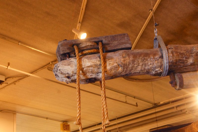
 John, The large wheels provided the necessary leverage for controlling the rudder(s), run manually by lines from the pilot house (if you look closely, you can see the ropes wrapped around the wheel's axle). As I understand it, American vessels eventually converted over to steam-powered steering, meaning the wheels got a lot smaller when mechanical leverage was no longer relevant, but Arabia was built well before that development. I wish I knew more about Australian steamboats, but is it possible they developed later and thus started out with non-mechanical steering and thus small wheels? For reference, here's a photo of the Arabia's original tiller and the block that held the ropes from the wheel way up in the pilot house: The other end pokes out of the stern to hold the rudder: Mark, I owe a clear debt to Kurt and Alan Bates for the clear diagrams and information they provided on pilot houses, as well as Brian's Chaperon which I consulted closely given the awesome job he did on a detailed pilot house.
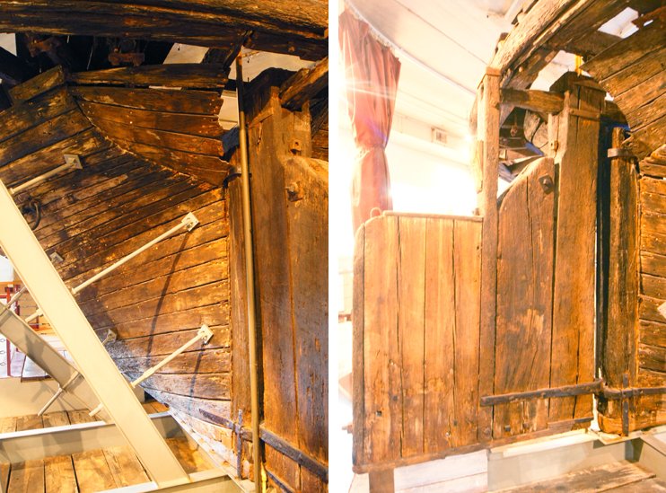
- 599 replies
-
- 9
-

-
- sidewheeler
- arabia
- (and 4 more)
-
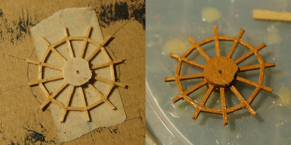
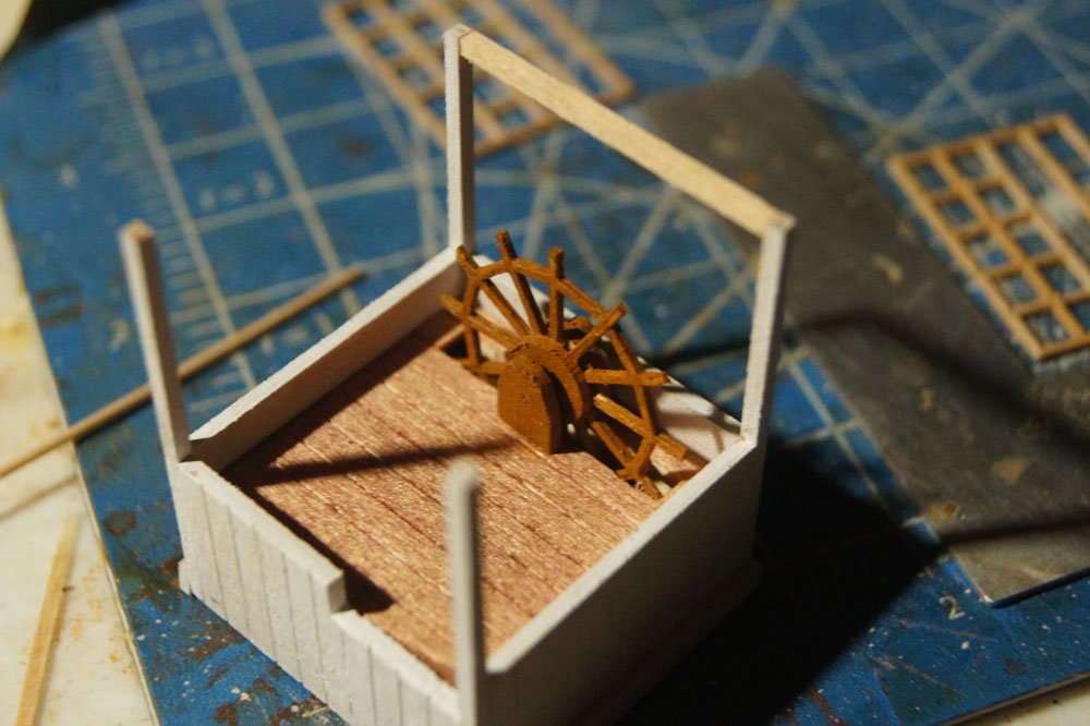
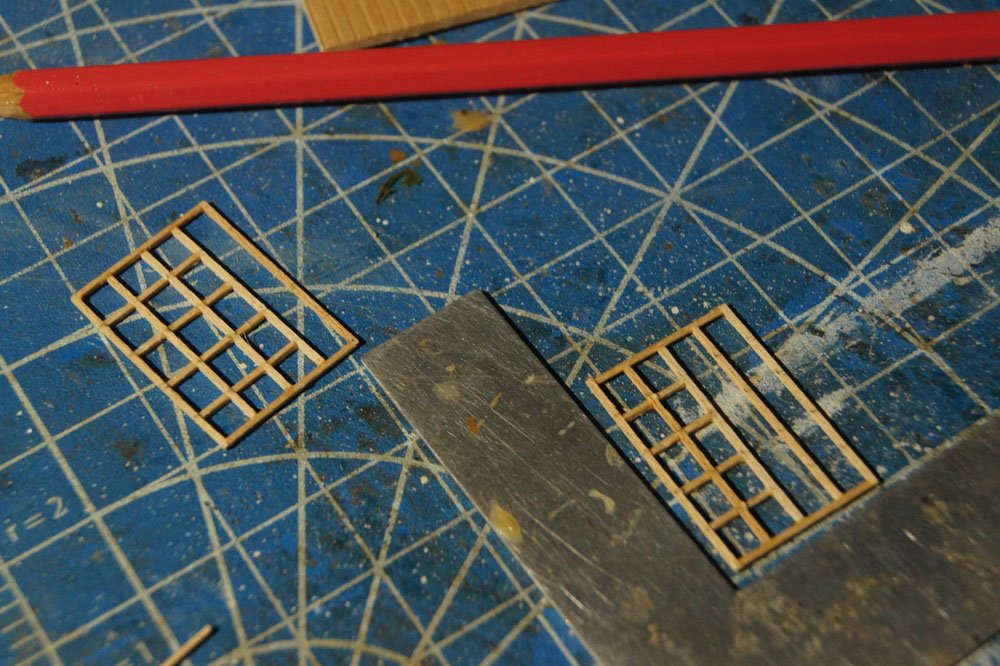
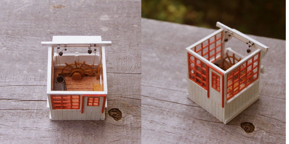
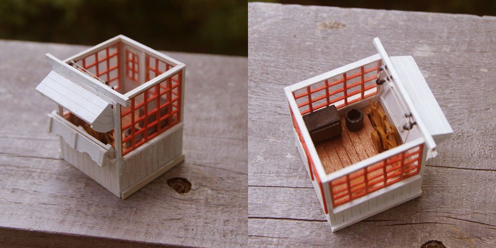
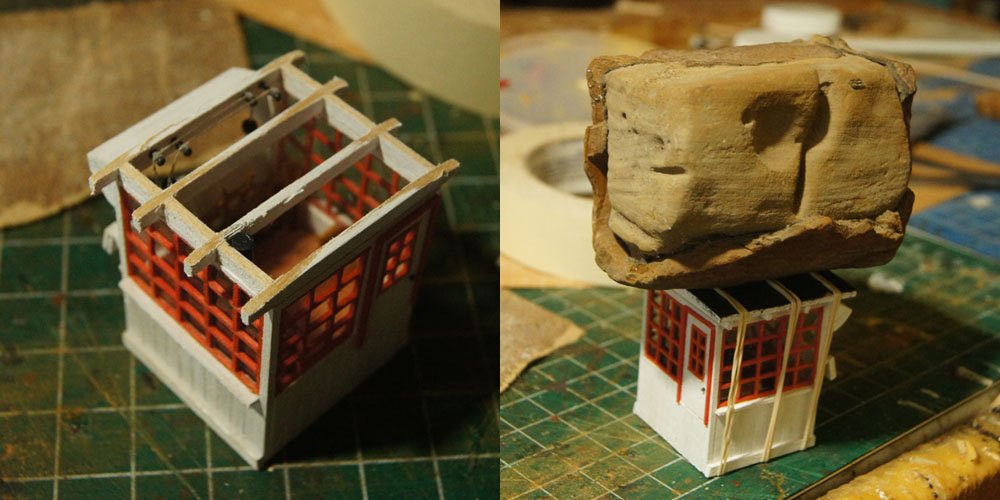
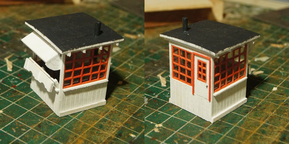
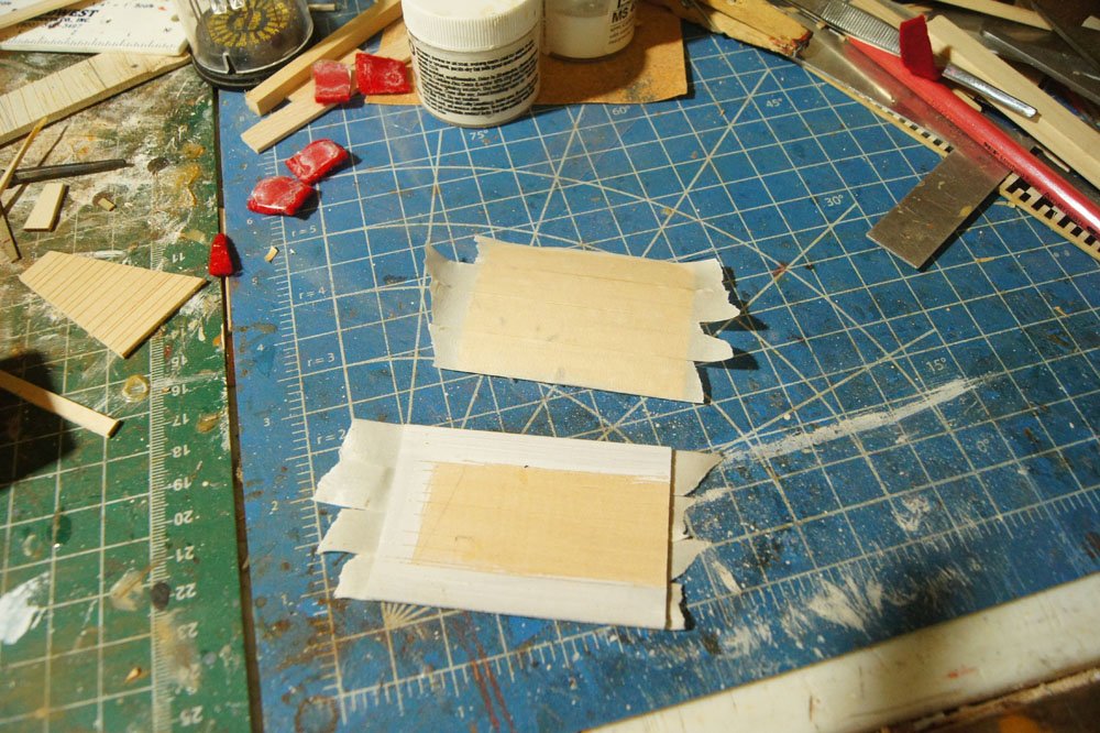
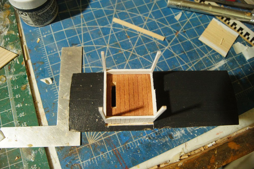
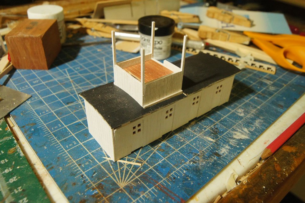
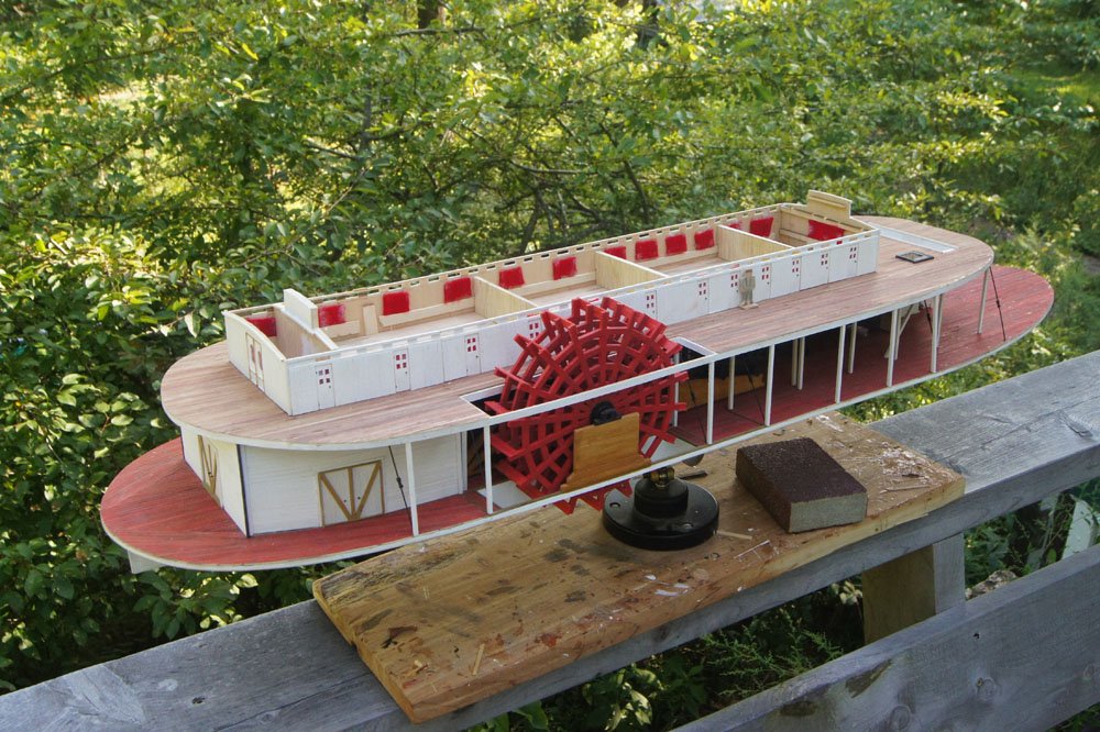
Thanks, popeye! This week's accomplishment was finishing the pilot house, which ended up being a fun little mini-model that I documented in a fair amount of detail. It was nice to take a break from the larger model and just focus on this one feature. I put a lot of detail into this since it's a visual focus point of the whole vessel. First, I built the wheel by laying out very thin strips of wood on double-sided tape and carefully fitting in braces around the circumference. When I liked what I had, I painted it. It's not as clean as if I'd bought a similar-sized one from Syren, but I liked doing it myself and its slightly rough style fits the rest of the model. This thing was super-delicate and I almost didn't get it off the tape in one piece. I then mounted the wheel in the pilot house, slotted into the floor the way all steamboat wheels were: Next, I built the windows using the same very fine strips and a lot of careful cutting and patience: After painting, I carefully glued sheets of clear plastic to the inside. My first attempt, I apparently used too much CA and it crazed the plastic, so I very carefully scraped the plastic off with a razor blade and tried again. I actually couldn't believe I got away with that, I was sure the window frame would shatter. The second time stuck with no crazing. I then added various internal details to the pilot house before gluing in the windows and door: Details include a small wood stove, a basic spittoon, a small bench, the hinged "bridle" that pilots used to hold the wheel in place if they needed to step away (next to the wheel at right), and two pull ropes for engine control. I ran these on criss-crossing lines as shown in various sources. The glue dried on the left-hand one a little weird; I'm saying a breeze is catching it through the open front window. The rods the lines are hanging off of are belaying pins from an old kit; the handles are parrell beads from same. There are a few other very small controls that could be added, but this thing is tiny and you'd never be able to see them clearly through the windows, so I decided this was enough to capture the proper feel. For a size comparison, the Chaperon model is in 1:48 scale while Arabia is in 1:64; this pilot house is ~1.5" to a side (~3.5 cm). At the front, I added the hinged/swinging shades that could be used to close off the normally open pilot house front during bad weather. Once I was happy with the internal detail, I added the rafters and the roof, which I made using the same masking-tape technique described in a previous post. This roof needed to be held down securely; three rubber bands took care of the edges but the top was bulging up too much, so I balanced a rock on it. Looks like she's bringing home a major geological sample from the Montana gold fields! And here's the finished pilot house with roof and stove chimney. I guess it's not 100% finished as I still need to add whistles, but it's close enough to move on from for now. This was really fun. Hope you like it.
- 599 replies
-
- 18
-
-
- sidewheeler
- arabia
- (and 4 more)
-
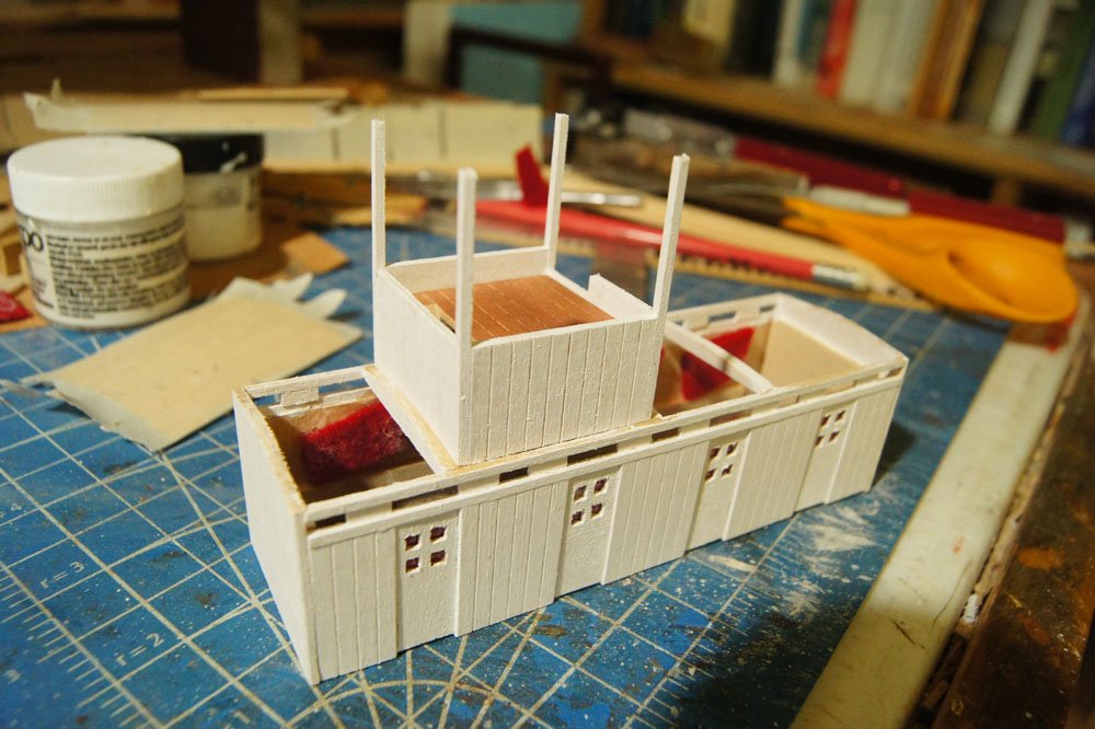
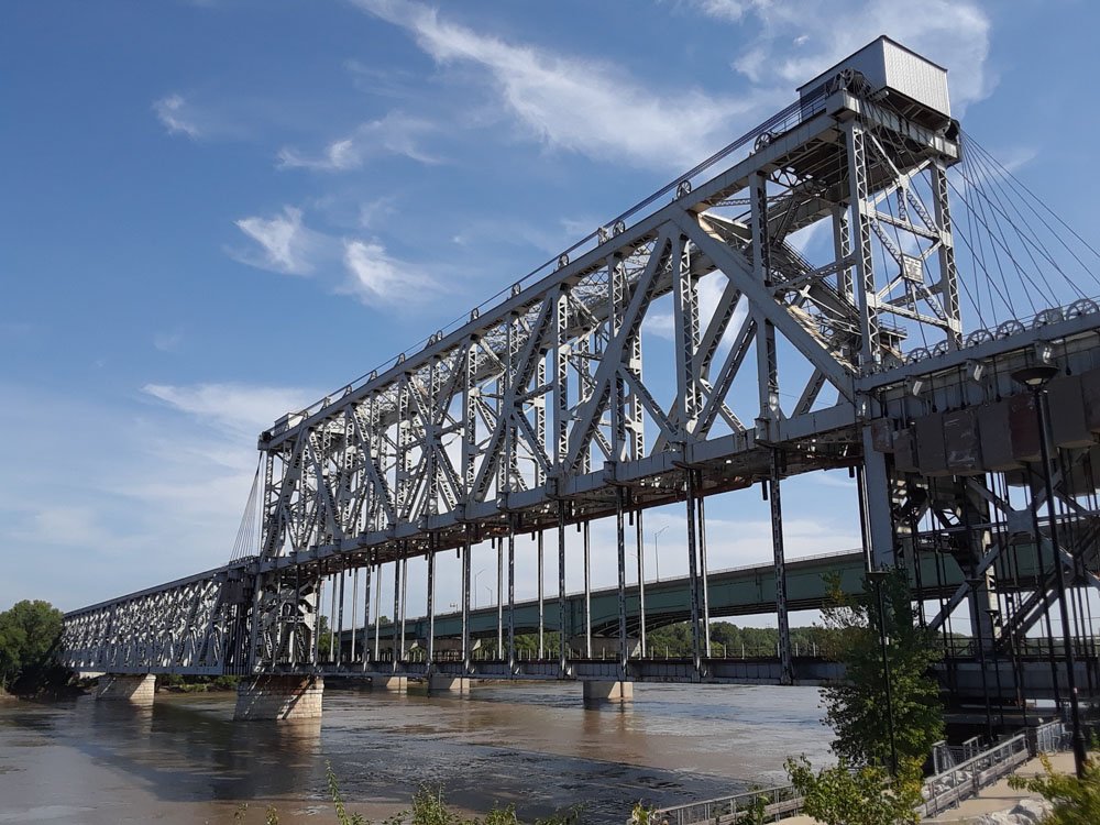
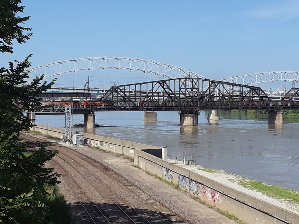
I started working out how best to build the hurricane deck (also known as the roof of the main cabins) and quickly realized I would need to work out exactly where, and what size, the hurricane deck cabins would be. That, in turn, meant I needed to do the same for the pilot house on top. So I changed plans and started building the rest of the superstructure first, since once that's in place it'll be easier to build the remaining decks around it. Above are the hurricane deck cabins. I made them exactly the same way as the boiler deck cabins, so didn't take any new photos of the process. The blocky beams are a special support structure for the pilot house, which I built as a separate unit that can be slotted into place, like this: Doing this made it a lot easier to work on each piece separately and will be especially helpful for adding lots of interior detail to the pilot house. Below is a shot of the pilot house removed, showing the interior bracing that slots into the beams atop the hurricane deck cabin. Next up, I worked on the hurricane cabin roof. Because this deck has some curvature to it, I used scrap pieces of scribed wood (scribing side down) as this takes a curve easily. This roof/deck would have been covered in strips of tar paper. Kurt Van Dahm's digital book on building Chaperon has a nice tip on how to simulate this, using strips of silkspan attached to a surface with matte medium and painted; it looks quite realistic. Having neither on hand, I made up my own adaption. I cut strips of masking tape to appropriate widths, smeared wood glue thinly on the roof surface, then carefully laid the masking tape strips with just a tiny bit of overlap at the seams. As a bonus, the moisture of the glue made the wood warp just about perfectly for the required curve! Below you see an upper and lower view of two such pieces; the lighting makes it hard to see the detail but hopefully it's clear enough. I used masking tape on my Bertrand to simulate the metal cladding on the chimneys, and it looked really good when painted and has yet to budge (I didn't even use glue that time). So I was confident it'd work here. After painting, the tape has a really nice rough texture and just a little bit of crinkling that looks pretty realistic. I trimmed the tape on all sides, then cut the pilot house gap out of the forward piece and test-fit them. Look closely and you'll see that I screwed up. I measured the width of the cut against the outer walls of the cabin, not the slightly narrower pilot house itself. After some roustabout phraseology, I quickly decided I could apply the old modeller's trick of "add useless but benign detail to cover up a mistake" and glued two thin strips of wood to either side of the pilot house, filling the gap nicely. I like how this looks (note that this is only a test fit). The masking tape has a good texture and you can just see the seams. I'll use the same technique for the much larger hurricane deck once it's laid down. In the meantime, there's a lot of pilot house detail to make, including some very small-paned windows (not sure how I'm going to scratchbuild these, especially if I want "glass" in them) and a proper wheel (I want to try the method used by Brian for his Chaperon, if I don't like the results I'll order one from Syren). I think I'll try and finish the pilot house next, so that this whole assembly can be attached permanently before I start building out the rest of the hurricane deck. Not my original plan, but it's working out fine. Finally, on a separate note, as a treat for my 40th birthday (actually tomorrow) we spent last weekend in Kansas City attending the big Irish music festival there and doing some other fun things. I thought some folks would be interested in seeing the ASB Bridge over the Missouri River. This is a pretty unique design (I think there's only a few others in the world) using a double-deck setup in which the lower level (carrying rail lines) raises by telescoping into the upper level (carrying cars and streetcars), allowing river traffic to pass without disrupting the upper deck. It was completed in 1911 and still carries rail traffic, though a newer road bridge was built just to the east in 1987 to carry road traffic. Just upstream, another active rail bridge: Shipping on the Missouri River is very minor these days, but rail traffic in KC is alive and well; the city's riverfront trail is a great place to set up for train-watching while the river rolls by. In these photos it's still pretty swollen from the heavy spring and summer rains; you can see a big jam of woody debris against one of the bridge piers. The Arabia sank less than 10 miles upstream from here.
- 599 replies
-
- 14
-
-
- sidewheeler
- arabia
- (and 4 more)
-
That's a tough decision to make, Mark, but it seems like the right one. In the end most of our projects will be somewhat ephemeral; we build them for ourselves and for our loved ones, so much of their value is in the process and the appreciation. If having it with her adds some joy to her life, then you've made the world a better place. Must really hurt to give it up, though. Thanks for letting us be part of the journey.
-
Brian, you may be able to hire a mill instead. We do all the timber work ourselves but hire out the milling because we only mill 1-3 times a year and don't feel like storing and maintaining a 30' trailer the rest of the time. Our folks just drive down in here with their portable mill, blast through a pile of logs in a day or less, and leave me with a big stack of lumber for projects (or sale in some productive years). Check various online listings or forums, I bet there's someone with a portable mill in your region. As for weather, sometimes it's the other way around. I'm a northerner who doesn't care for hot, humid summers but will spend far more time outdoors in the fall and winter, especially doing timber work. But the days are short enough that long evenings happen anyway, so there's that.
- 599 replies
-
- 4
-
-
- sidewheeler
- arabia
- (and 4 more)
-
Mark, I'm sorry to hear this. I do want to thank you for sharing all that you've done thus far, so many of us have learned so much from you. Whatever choice you make down the road, you've helped so many people by sharing this that the project is already a wonderful achievement.
-
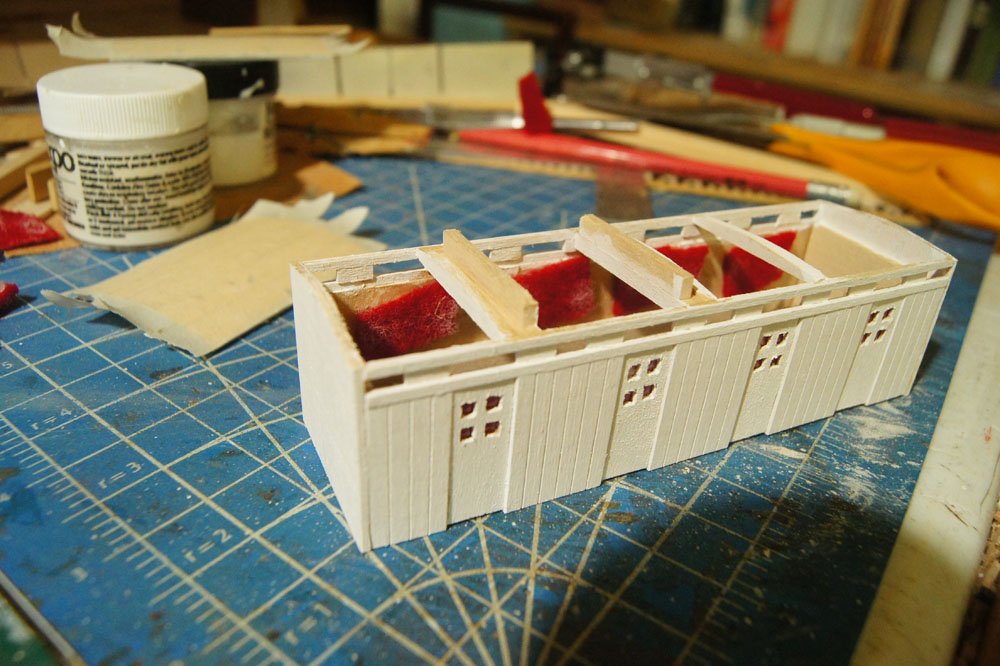
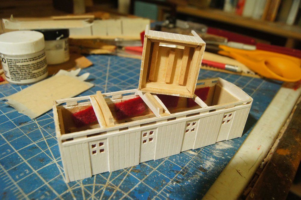
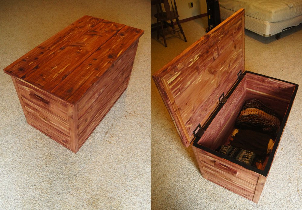
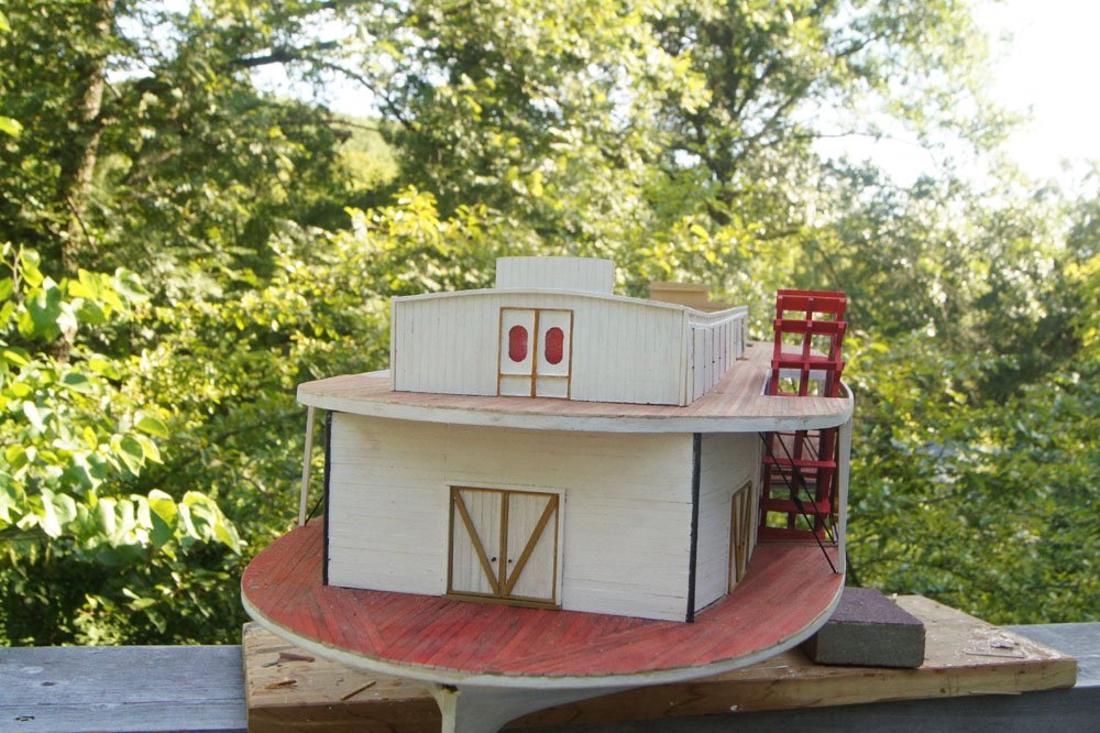
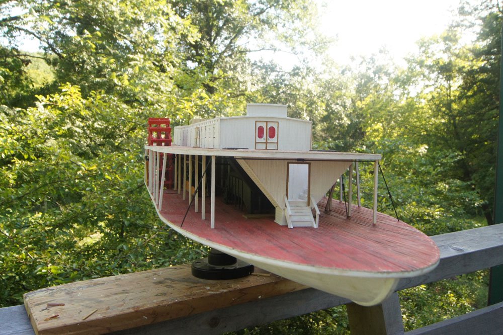
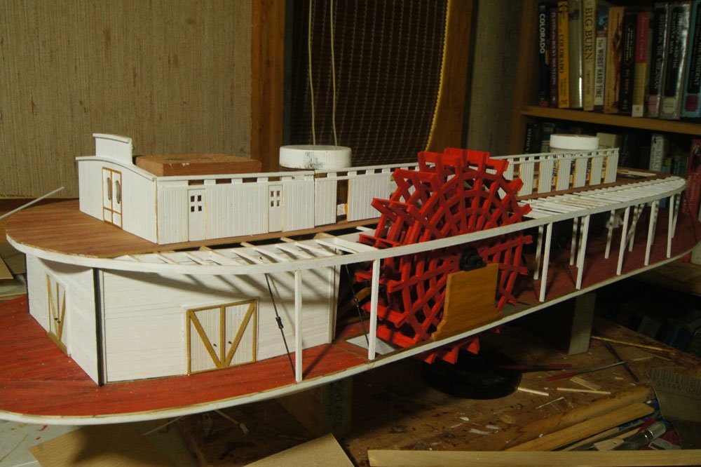
So if you're wondering why it's been three weeks since an update, it's partly because I've been working on another wood project: a cedar chest to wool sweaters and other moth-prone treasures. This is made from Eastern Red Cedar cut & milled on our property; if you look closely you'll see some chatter marks from the bandsaw mill that I couldn't get fully sanded out (I don't have a planer). Mrs. Cathead actually likes it that way, as a reminder that it's from our place and not just random wood. It's been sucking up a lot of my project time but is finally done. But with that done, it's back to the Arabia. I finished all the walls for the main cabin, including "glassing" them with clear plastic and attaching pieces of scrap red felt from Mrs. Cathead's sewing supplies for curtains (i.e., viewblocks to the unfinished interior). I added handles to the doors in the same way as on the main deck (by drilling in small pieces of black wire) and drew on hints of hinges with a fine-tipped market. So here's what she looks like with the outer main cabin walls permanently installed: I have to say, I think she looks pretty cool. Next up is starting to install the more delicate supports for the center clerestory windows and the various roof beams; this will tie into building the upper paddleboxes. In other news, there's a new steamboat build log to check out if you want: Tom in NC is giving a new twist to the classic Chaperon kit by re-imagining it as a prohibition-era den of vice. Also, while researching a question in Brian's Chaperon build, I discovered that newspapers.com is a great resource for finding contemporary news clippings about steamboats. For example, here are two notices about the Arabia's sinking that appeared in the Louisville (KY) Daily Courier and the New Orleans Times-Picayune. Note the time delay for news in those days; she sank on September 5, 1856, but the Louisville notice appeared September 10 (with a September 9 byline from St. Louis) and the New Orleans notice appeared on September 17. We'll see if progress is more steady for a while with that cedar chest out of the way. As always, thanks for reading.
- 599 replies
-
- 16
-
-
- sidewheeler
- arabia
- (and 4 more)
-
Great work! Love the added bumpers, they're definitely a realistic touch. Regarding Cairo, have you looked at BlueJacket's kit? It's mostly wood (you can view a kit-contents video at that link). I'm strongly considering that as my next project. Also, there's a fantastic large-scale build of the USS St. Louis (a sister ship to Cairo) being build by the Gateway Model Shipcrafters club in St. Louis. As far as I know they're relying heavily on Cairo plans, so you could contact them for advice and resources. I suggets reading their log as a reference; I've seen the in-progress model in person and it's amazing (and huge). They've been maintaining the log intermittently lately but I can put you in direct email contact if you want. Regarding a sidewheeler prototype, there are certainly lots to choose from. I love that UW site as a resource; it's where I found the Mary McDonald photo collection I've been using as a reference for Arabia. I also have a copy of Way's Packet Directory, a nearly comprehensive listing of all known interior riverboats with varying levels of information on each one (history, dimensions, tonnage, masters, features, sale history, etc.), so I'd be happy look up any given craft for you. For example, there are three entries for sidewheelers named Selma. The first was built in 1845, served out of Mobile, AL, and was lost in a collision in 1850 (here's an 1846 newspaper clipping about her). The second was built in 1853 under a different name but was renamed in 1856, primarily serving out of New Orleans until being dismantled in 1860. The third was built in 1867 and also operated out of New Orleans (here's an 1868 sales notice from the New Orleans Times-Picayune). The latter two were roughly the size of Arabia while the first one was a little squirt about 1/3 the tonnage. I'd guess yours is the third one but hard to say without more info.
- 133 replies
-
- 3
-
-
- chaperon
- model shipways
- (and 2 more)
-
In fairness, the kit doesn't provide any engines because they're hidden within a closed superstructure (which Tom has opened up), so Tom would have to scratchbuild them, which he may or may not want to do (they're pretty complicated even in simplified form). They would take up enough room that you couldn't easily fit any other gambling space in that area and it's certain that no one seeking any pleasure would want to be anywhere near them while in operation. Even quiet, they'd be greasy and dirty enough that fancy gamblers probably wouldn't appreciate the chance to rub up against them. The boat as a whole has more than enough space for all intended purposes, especially up on the boiler deck, so in theory Tom could move a lot of that up there, but that's not the route he's taken so far. Seems to me the most practical propulsion solution in this case would be to install diesel engines and props, leaving the paddlewheel as a dummy. These could all be fit below decks, leaving them out of sight (except the props, which aren't hard to add). Or maybe Tom's fella got his hands on a towboat that he uses to move his pleasure barge around when he needs to. Tom, you've obviously piqued some interest with this yarn of yours, good for you. It's your model, so whatever you decide works best for you and makes you happy is ultimately the right choice.
-
I think your fella converts the boiler, not just into storage, but into a giant liquor tank. Different spirit for each boiler tube and taps running to the bar, maybe converting the steam lines for this purpose.
- 18 replies
-
- 1
-
-
- chaperon
- model shipways
- (and 1 more)
-
Tom, You're pretty deep in already, but Kurt Van Dahm sells an excellent extended tutorial on building this kit that I highly recommend. It would have answered some of the questions you've already passed by and will almost certainly answer more down the road. Is part of your narrative is that the boat is moored somewhere for good, as the gambling tables have taken over the engine room?
-
Scale matters to anyone who cares about how much room the finished model takes up in their home or the cost of the resulting case.
-
Requesting feedback for future MSW Group Projects
Cathead replied to Chuck's topic in Group Projects on Model Ship World
I'd love to see a longitudinal section that shows all the decks, cabins, holds, etc. of a vessel. Much of the joy of modelling, for me, is learning how things work (or worked) and closed models leave out so much of the good stuff. And it'd be very different from all the standard cross-sections. Lots more visual interest for viewers, too. -
I actually haven't built Chaperon yet, but it's on my someday list.
-
I'm always up for another proper steamboat build. Glad to have you on board and looking forward to seeing what direction you take this in.
- 23 replies
-
- 2
-
-
- model shipways
- chaperon
- (and 1 more)
-
Just found this and it's pretty cool. Nice job on a creative approach to a different kind of ship modelling. Can't wait to see where you go from here.
-
It'll make you want to build models in 1:87, that's for sure. That and the widespread availability of window/door castings, figures, and other such things were a major factor in deciding to build the Bertrand in that unusual (for ship models) scale. Well, that and I wanted to display it on my model railroad depicting a late 1850s Missouri River town.
- 599 replies
-
- 4
-
-
- sidewheeler
- arabia
- (and 4 more)
-
Brian, It's purchased from Northeastern Scale Lumber, which primarily supplies model railroaders. All my stock is leftover from when that was my primary hobby focus, I built a lot of my own buildings. They have a wide array of different siding styles (boards, clapboard, board and batten, etc.) in different widths. Well worth checking out.
- 599 replies
-
- 5
-
-
- sidewheeler
- arabia
- (and 4 more)
-
Nice! Great to see you back at work. Is your new home still in "far north Texas"? I worked in the Panhandle for a summer after college, at Alibates Flint Quarries National Monument and Lake Meredith National Recreation Area, doing geological surveys for both parks as well as public interpretive work.
- 133 replies
-
- 2
-
-
- chaperon
- model shipways
- (and 2 more)
-
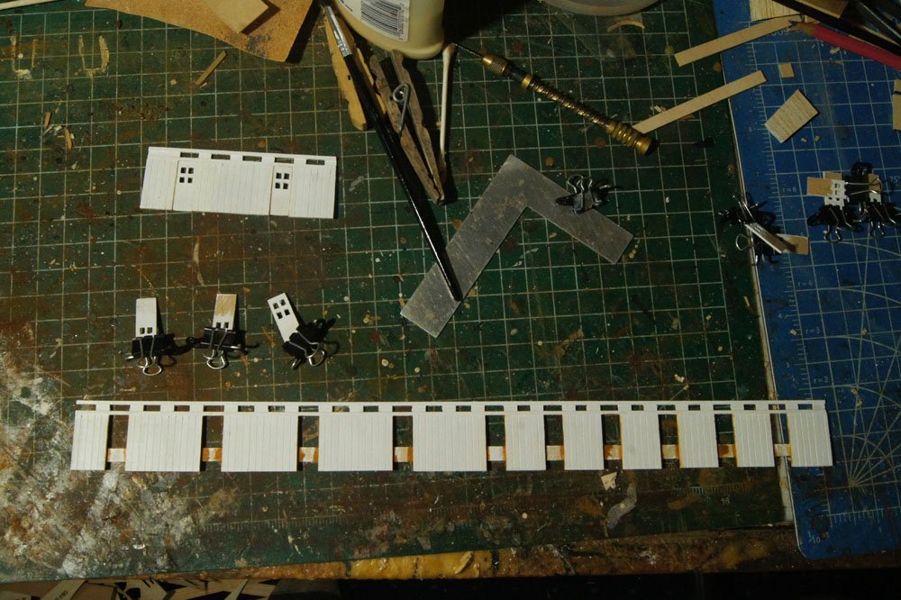
I worked on the main cabin walls this week. Here's a small bit I made to test out my intended method: It's pretty straightforward, just panels of scribed wood spaced below the upper window assembly, which keeps the whole thing straight. I made the doors the same way as before, by drilling holes and then finishing with knife and file. I have to make lots of these and they're pretty fiddly, but I listen to an audiobook and it goes pretty smoothly. Close-up, you can see some rough edges that I've been having a hard time fully smoothing down, but they seem to blend into the background when viewed beyond a camera lens. Here's the rest of the starboard outer wall: All the doors are made and painted but I haven't installed them yet. The backing strips holding this together and straight are scrap from past wooden kits (the stuff around laser-cut parts); I have a whole box of this stuff because I hate throwing things away, and it comes in really handy here as it's straight and strong but doesn't cost me anything. Here's the wall loosely placed on the model for visual inspection: Certainly gives the right idea. I think this came out well and the next one will go faster now that I have the method down. Thanks for reading.

- 599 replies
-
- 19
-
-
- sidewheeler
- arabia
- (and 4 more)
-
Chuck already has a dedicated thread in this same section, where people praise and otherwise interact with him and where he routinely answers questions and provides updates. It's very active and I'd suggest that there's no reason to duplicate it here. https://modelshipworld.com/topic/12476-syren-ship-model-company-news-and-forthcoming-new-projects-products/
-
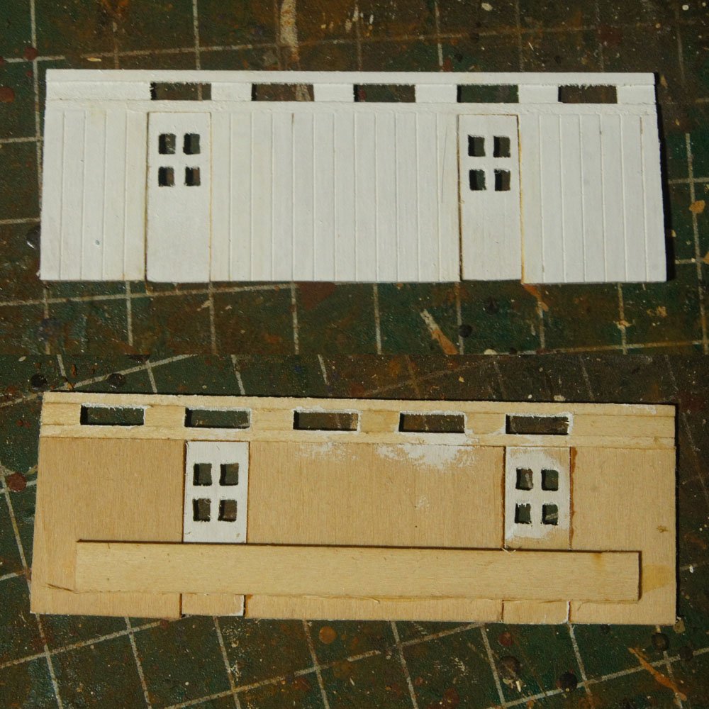
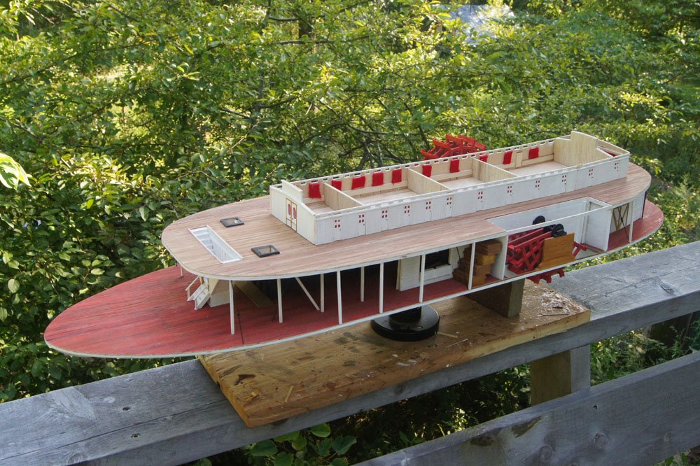
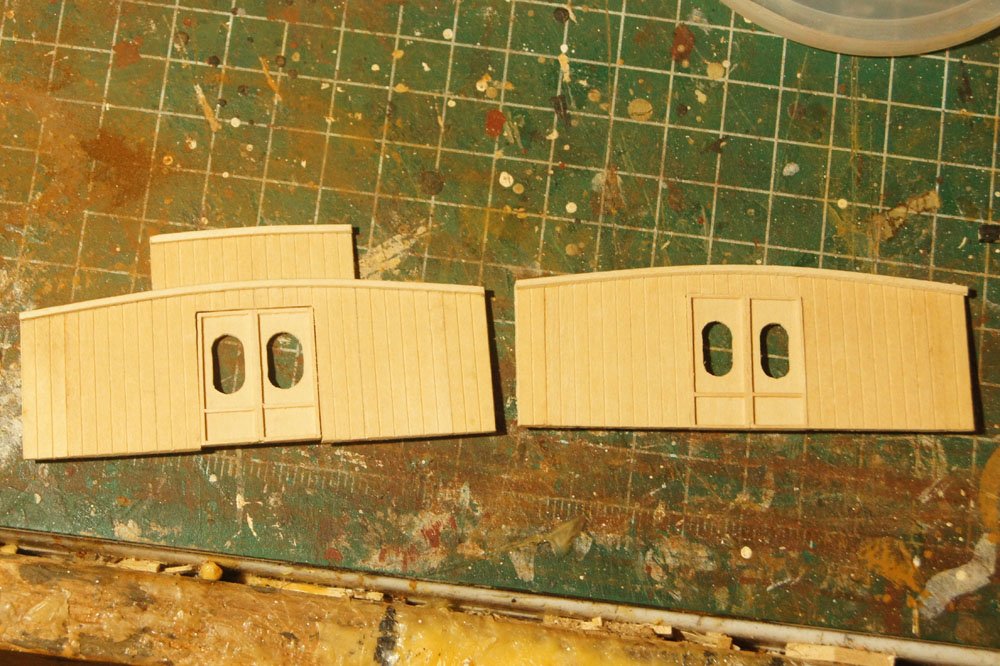
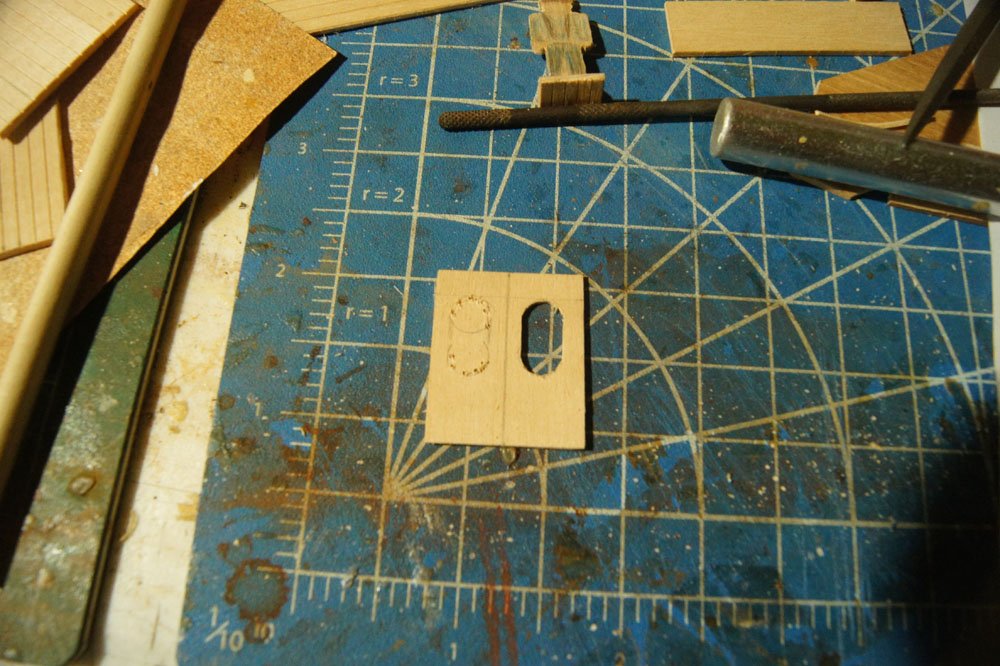
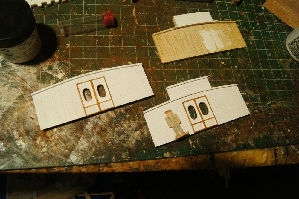
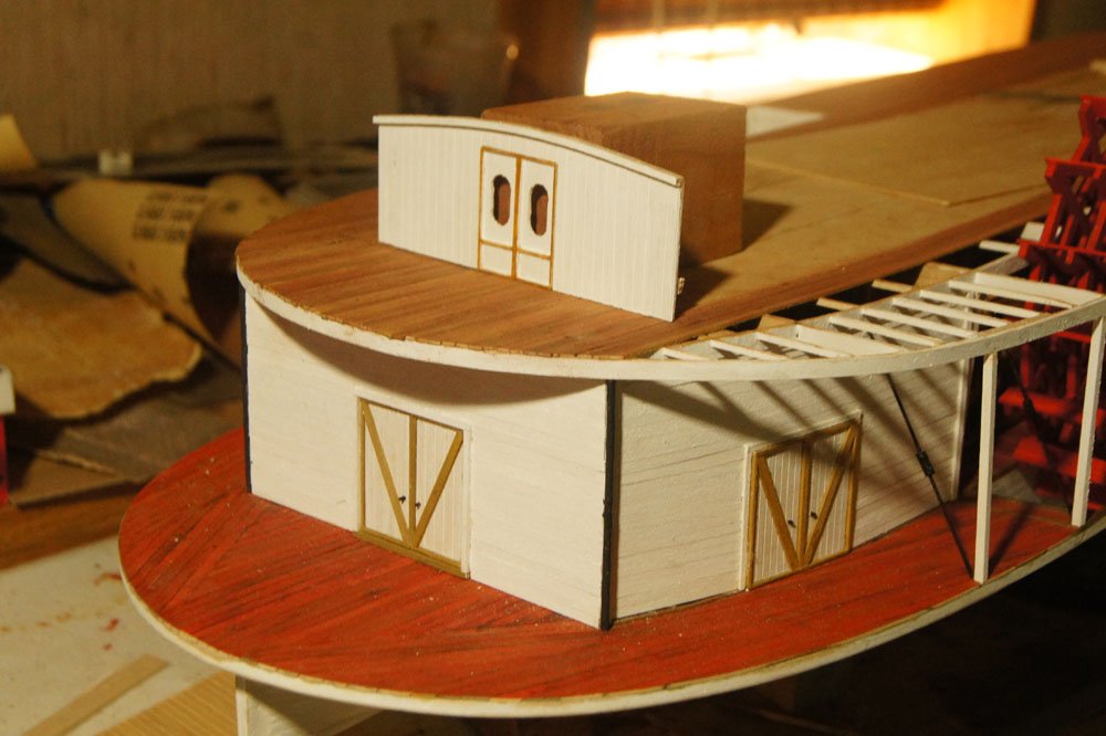
I took a break from planking to work on the boiler deck structures (i.e, the main cabin). This is complicated as it contains multiple curved deck levels above and a raised central skylight running along most of its length. I started by drawing out the shapes of the fore- and aft-most walls, since they define the curve of the hurricane deck (the third one up, after main and boiler). I decided to use pre-scribed wood for the cabin walls at this level for three reasons. First, they need to be especially structurally solid given their complexity and I can get their shapes more similar using solid pieces. Second, they won't be as visible as the main superstructure walls because they'll be more hidden under overhanging decks. Third, I've been underestimating my strip wood use and this gets expensive to keep reordering, whereas I have plenty of scribed stock sitting around. So that's how it is. Fore (left) and aft (right) main cabin walls with handmade doors. The ribs along the top provide extra support for the next deck up. I put the worse of the two doors on the fore cabin wall as this will be especially well-hidden under a deep and long overhang, where as the aft one will be a lot more visible. I made the doors by tracing the oval windows (using a dowel for the curve), drilling out their outlines, then cutting and sanding the hole. I then attached thin strips of wood to make the framing, as seen in the first photo. Here they are painted and installed in the walls. The third piece (upper right) sits a bit forward of the aft wall because the skylight doesn't run all the way back. This will be clearer when I get further along in the build. Next step on these is glassing the windows and adding some curtains to block the view, as I don't want to show any interior. These are the doors that access the main dining/social cabin that runs the length of this structure; the lower portions to either side house the individual cabins, kitchen, and other areas that are accessed from doors on the outer and inner walls. Here's a cross-section of a typical sidewheeler from Wikimedia Commons in case it helps clarify what I'm working on here (the area above the boilers): As a preview, here's the aft-most wall propped up in its intended location. I like how these came out; they were a good test for the even more complicated task of building the long side walls full of cabin doors and other details, which is next. Thanks for reading!
- 599 replies
-
- 16
-
-
- sidewheeler
- arabia
- (and 4 more)
-
Does anyone have a sense of how accurate the kit is? I've read that some other kits are just modified version of other ships rather than actually designed to be the Beagle.
-
Good point on not waiting too long, wefalck, especially with soft basswood. I'll try that.
- 599 replies
-
- 3
-
-
- sidewheeler
- arabia
- (and 4 more)
-
Brian, I'm using wood glue because (a) I've heard mixed reviews about the longevity of CA and (b) it's more benign to be around, which is important to me. CA gives me a headache pretty quickly, while I can use wood glue all night long. Unlike Chaperon, I'm not gluing planks to a smooth surface but just to the very thin cross beams above the main deck, so spreading glue along the bottom of the plank would (a) waste a lot of glue and (b) create a really ugly under-surface as the boiler deck can be seen from below. So what I'm doing is placing small dots of glue on each beam and then settling the plank over it. What's happening isn't seepage directly up through the plank, it's bits of glue squeezing upward in the seams between planks, then soaking in from the side or top. It creates the little darker patches you can see if you look closely at the planking photos. The best approach is just to be really careful in how much glue is used, but sometimes I get it wrong or it gets up there anyway. Also, early on I made the mistake of trying to wipe it up right away, which just spread wet glue further over the absorbent surface and made the spot bigger. I think it's better to let any beads dry and then scrape/sand them away. The core problem is that the planks aren't sealed in any way, and soft basswood is really absorbent. But that's the price of doing the individual planking the way I like it done in this case (i.e., without paint). Given that most of this will be under another anyway and only seen in partial shadow from the side, I don't think most people will notice. It would cost me points in any model competition for sure, but as that's not my goal it's ok. Thanks for the feedback, it's nice to have other steamboat modellers on board. My brain is already working ahead to thinking about trying Chaperon and customizing it various ways to backdate it to a mid-century Missouri River sternwheeler, and the more build logs there are the more I learn about the kit.
- 599 replies
-
- 5
-
-
- sidewheeler
- arabia
- (and 4 more)