Cathead
-
Posts
3,557 -
Joined
-
Last visited
Content Type
Profiles
Forums
Gallery
Events
Everything posted by Cathead
-
 Thanks so much for updating this! Missed hearing from you. Lovely work.
- 48 replies
-
- 3
-

-
- queen anne barge
- Syren Ship Model Company
- (and 1 more)
-
Change Theme
Cathead replied to cog's topic in Using the MSW forum - **NO MODELING CONTENT IN THIS SUB-FORUM**
Sorry to get ahead of you. Not always clear whether a given question is helpful because it is unique or hasn't been noticed, or unhelpful because it's already on the to-do list. -
That's beautiful. As you say, I really like how the different lighting conditions bring out different aspects of the plating. You're also spot-on with the podcast idea; for me it's audiobooks but the concept is the same.
- 950 replies
-
- 2
-
-
- syren
- model shipways
- (and 1 more)
-
The standard method for simulating treenails often uses a drawplate, but that probably wouldn't work if you intend them to work structurally rather than aesthetically. If you're going to sacrifice authenticity for practicality in this case by abandoning rivets, why not just use glue and simulate the rivets? It'd be a heckuva lot easier and would look more authentic. I can't help on your actual question, I have no experience with that.
-
Change Theme
Cathead replied to cog's topic in Using the MSW forum - **NO MODELING CONTENT IN THIS SUB-FORUM**
Looks great, thanks so much. I tried to make clear that I wasn't whining, just providing some feedback on functionality, but I apologize if it came off as critical rather than curious. I'm deeply appreciative what you all do to keep this running. -
Change Theme
Cathead replied to cog's topic in Using the MSW forum - **NO MODELING CONTENT IN THIS SUB-FORUM**
I also just experienced the new theme. My concern is that all the text is now a light grey that is very difficult and eye-straining to read against a white background. I went into my account settings and could find no way to change those display options. Is there a way for me to set the basic text back to black or is it now built into MSW? Regardless, it's giving me eye strain within a few minutes of looking at the site and I'd be very grateful to have black text back. I realize site managers have a thankless job when things go well but only ever hear from us with complaints, so I apologize. But this is really affecting my ability to read the site. -
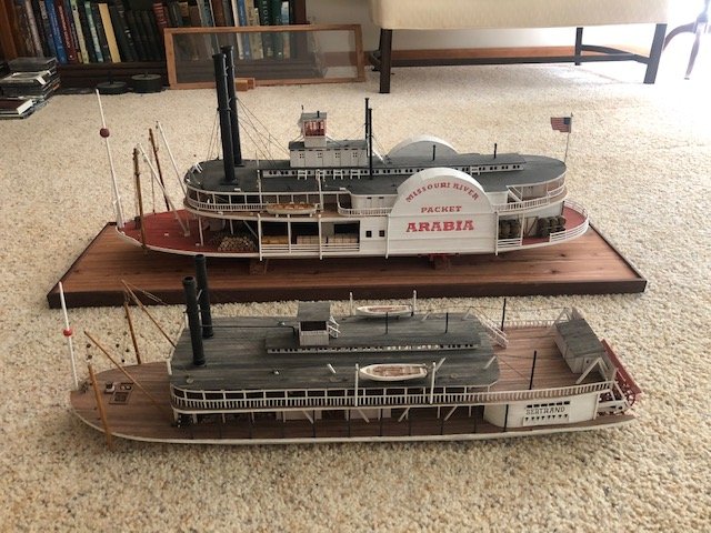
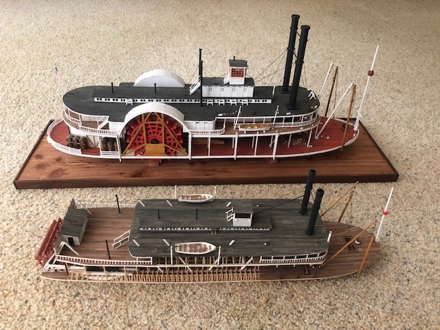
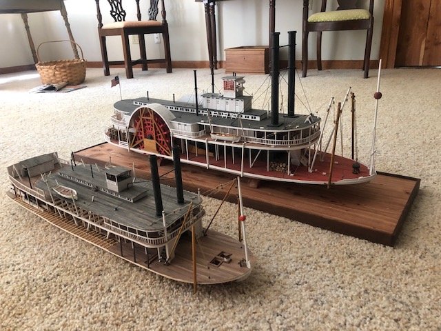
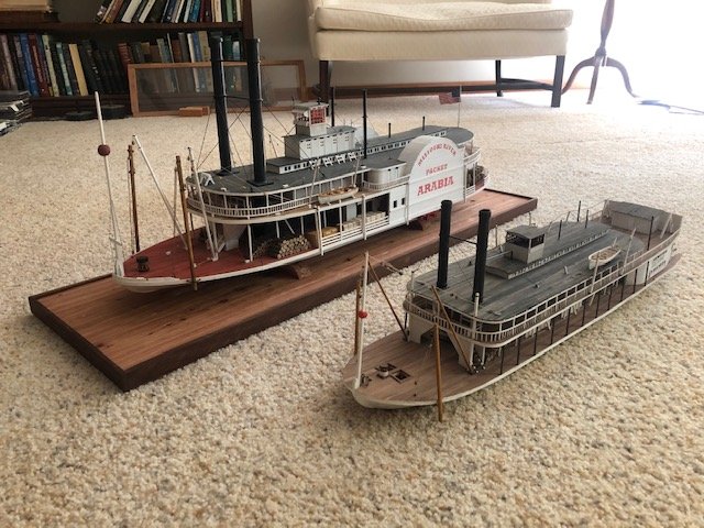
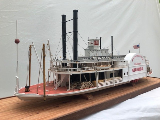
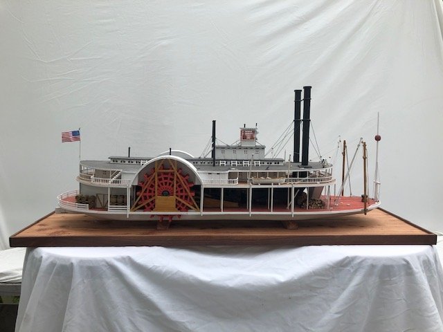
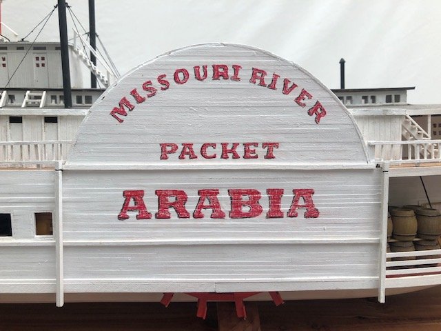
Good idea. Here's a few quick shots on the floor (too hot and sunny to go outside). They were similarly sized: Arabia: Length 171', beam 29' (hull; with guards, around 48'), tonnage 222 Bertrand: Length 161', beam 32' (hull; with guards, around 40'), tonnage 251 I also made a mistake in the last post (now corrected); Bertrand was built at 1:87, not 1:72.
- 599 replies
-
- 14
-
-
- sidewheeler
- arabia
- (and 4 more)
-
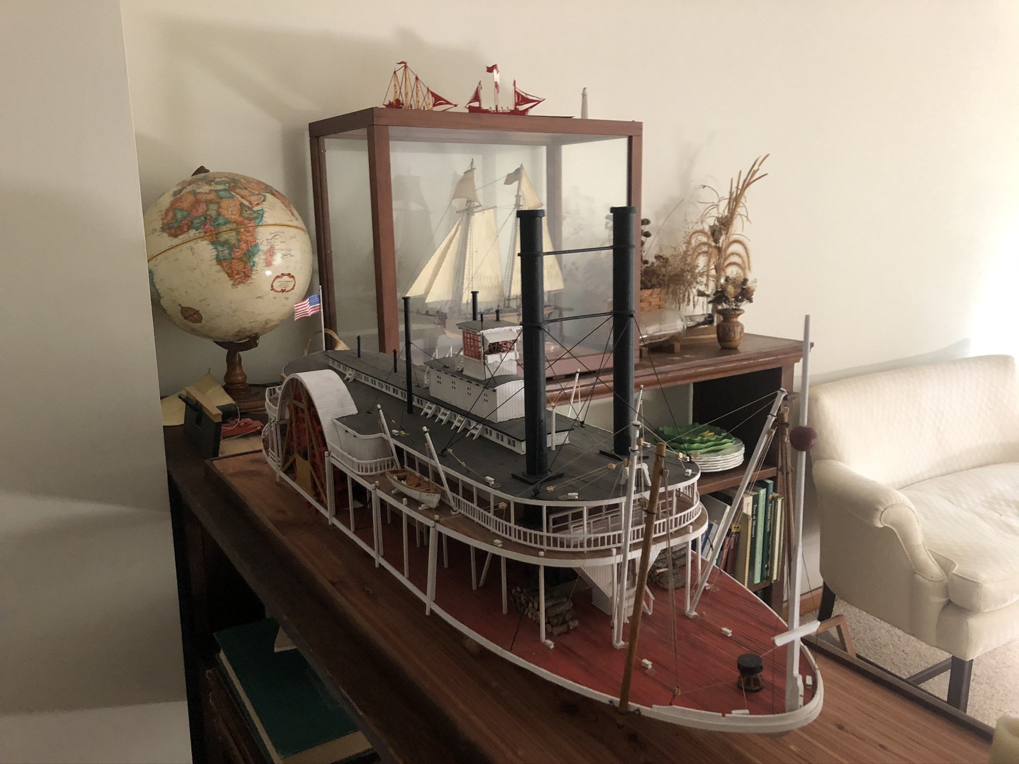
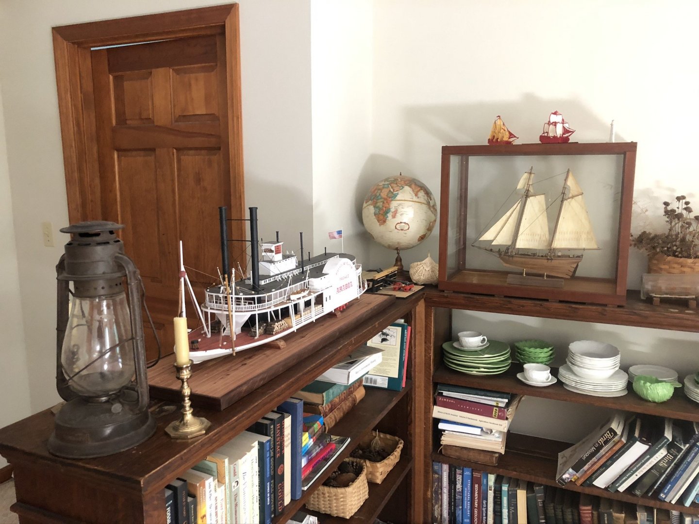
Two last shots of Arabia in her display location in my model/nautical corner of the house. We might move her somewhere else once I get a full case figured out, but this is good for now. I like that the bookcase opens on both sides so it's easy to view the open and closed sides of the model. Out of shot on a lower shelf is my model of Bertrand, another open/closed sided steamboat, so the two go well together here. Note that the Arabia and the revenue cutter behind her are the same scale (1:64); I think it's a fun visual comparison. Some of you asked about my next project. Having bought a Byrnes table saw over the winter, I had been planning to shift to scratch-building full-time using wood harvested on my farm. I have billets of maple, cherry, and various fruitwoods that have been drying for up to two years and will provide all the modelling wood I could possibly use. My goal was for the cost of the saw to replace the cost of kits and wood in our budget, which it should. There are a variety of interesting Missouri River craft on the agenda, including the boats used by the Lewis & Clark expedition and some smaller steamboats used on tributaries of the Missouri River. However, the last few months have been extremely stressful for reasons from personal to global, and my brain is a bit fried with trying to keep track of this complicated build. Moreoever, the libraries and historical societies I might otherwise visit to do primary research in Missouri craft are closed or restricted. So I bought one last kit as a simpler relaxation project: the Dusek Viking longship in 1:35 scale (note that the scale of my builds keeps going up, from 1:87 Bertrand to 1:64 Arabia to 1:35 Viking ship; this could be a problem down the road). I am of Norse descent (my beloved grandfather was extremely proud of his heritage), my father-in-law was a scholar of Old English and the Saxon period, and I'm a huge fan of Bernard Cornwell's long "Saxon Tales" series of historical novels (better known as "The Last Kingdom" once a TV show based on it was launched). So this will have some meaning for me while at least letting me follow someone else's instructions. I do plan to make some modifications for authenticity/uniqueness and to replace some of the kit wood with my own home-cut-and-milled; I may also use the plans to build several versions using my own wood. I'll launch a build log eventually, but will likely be dormant for a while. The next few weeks will involve helping my elderly in-laws move closer to us, which would be a massive enough undertaking if there wasn't an ongoing pandemic, so I don't think I'll have a lot of free time until sometime in July. I'll post a build log link here once I start it, for anyone who wants to follow along. Thanks once more for your support and interest.

- 599 replies
-
- 12
-
-
- sidewheeler
- arabia
- (and 4 more)
-
No worries, thought I'd mention it just in case.
-
Great choice, looking forward to following along. In case you're interested, MSW user Kurt Van Dahm has a great digital guide to building this model that has a lot of useful tips and insights for this kit; I highly recommend it. Here's a link where he describes it and explains how to order.
-
Four mounting points make a lot of sense, I did the same thing with Arabia. These flat, wide bottoms are perfect for that and I feel a lot better with the foursquare support. Treenailing in the false keels is a good touch, too.
-
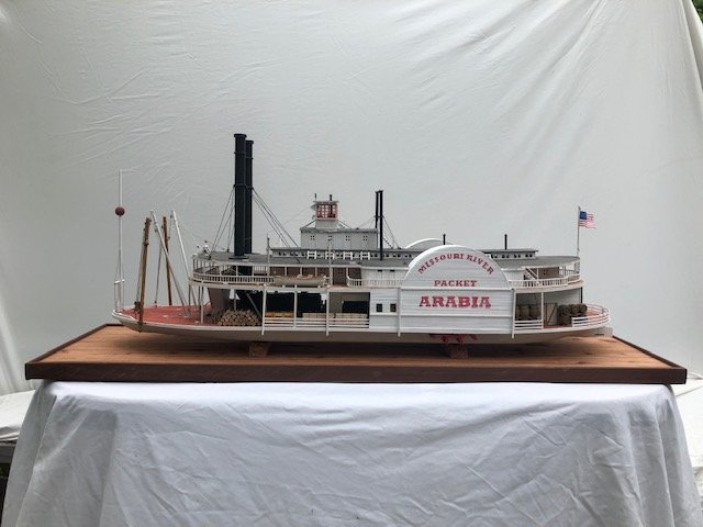
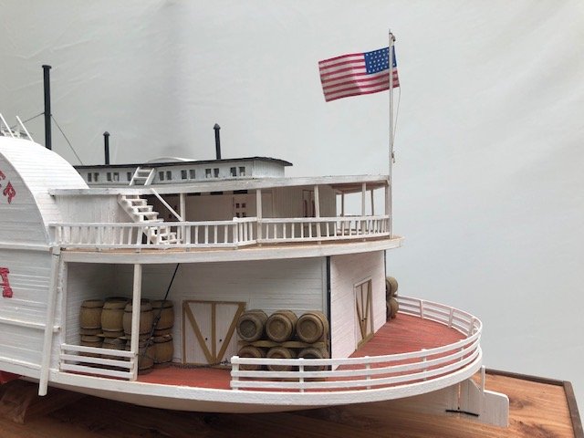
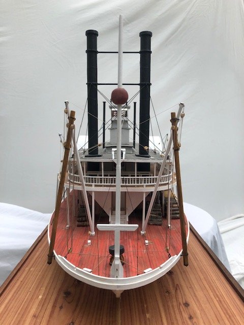
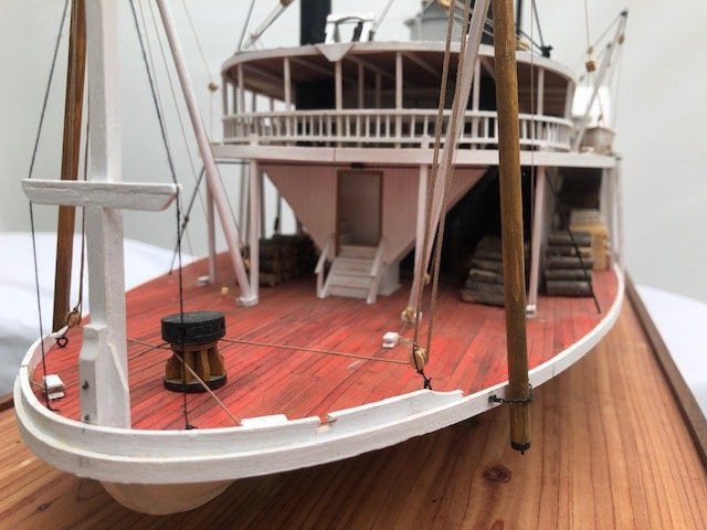
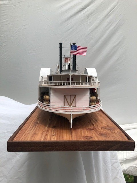
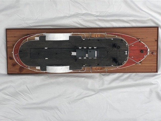
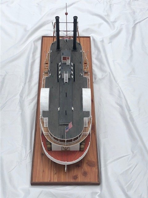
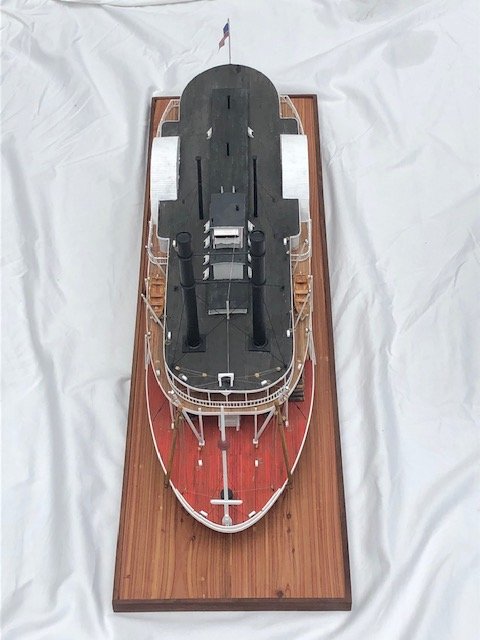
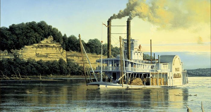
I took advantage of a cloudy afternoon to take a break from regular work and do a quick photo shoot on my porch, using my phone with a few rumpled sheets as backdrops. May try to do a nicer job someday but the model's not going anywhere and this let me feel a sense of closure. It was pretty windy and you'll see the flag changing positions! First, a few overhead shots: Stern views: Bow views: Side views: Overall views: Painting for comparison with the last view: Thanks for everything.
- 599 replies
-
- 24
-
-
- sidewheeler
- arabia
- (and 4 more)
-
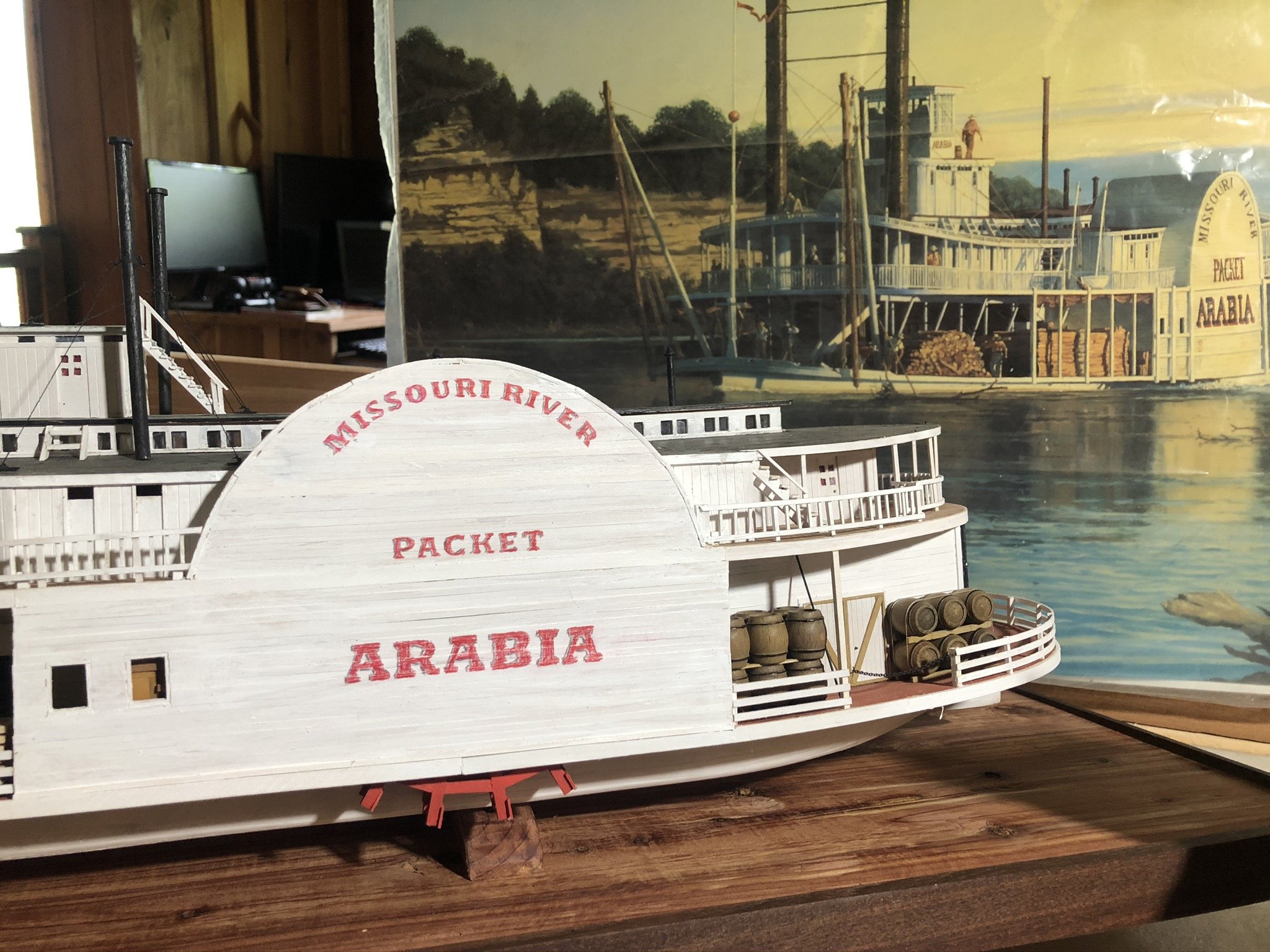
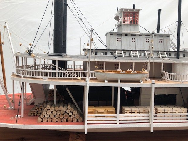
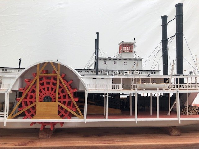
I finally got an updated (larger) stencil from the neighbor teen and relettered the wheel housing. I like this much better: Compare with the earlier, too-small version: And with that, she's done. Next post will feature some final shots. Wow. I'm having a hard time adjusting to this, after 2 years and 8 months, the longest I've worked on any model project. I can't emphasize enough how important all of you have been, through likes, comments, suggestions, criticisms, and support. Even when I didn't take your advice, I listened to it and learned from it. You've helped me create something pretty special to me, and maybe to others if I ever get to display it somewhere other than my quarantined rural farmstead. Thank you.

- 599 replies
-
- 16
-
-
- sidewheeler
- arabia
- (and 4 more)
-
Model Expo is shipping and they sell packaged strips in all kinds of dimensions that are very useful.
-
That's what "fairing" refers to; bulkhead edges need to be filed to an angle that matches the flow of the planks. I thought that's what we had been talking about. Have you read any of the planking tutorials here on MSW? They'd be pretty helpful. If your bulkheads haven't accounted for this, there's a way to fix it. Many of us, when fairing, mistakenly take off too much at some point, resulting in the plank not sitting properly as you describe. You could use filler as you suggest, but it's often easier to glue a thin strip of wood to the outside edge of the bulkhead, then sand this back down to the properly faired angle.
-
Wait, so are you or aren't you burning it? It's your choice, just confused as to the plan.
-
I agree with Petr. If you want to have it just-so for your own satisfaction, that's fine, but it should have little bearing on whether it floats (that would seem to relate more to whatever sealant is used and proper ballasting, not precise planking). As for burning, I recall reklein sharing photos of a model he gave a proper flaming burial to (earlier in this thread), but I don't recall Kris saying that was the purpose of this model (just that it represented a personally symbolic "burial"). Did I miss something? I'm still not sure about the reasoning regarding needing to get the fairing right before gluing in the bulkheads.
-
Well done and thanks for sharing. A beautiful build.
- 66 replies
-
- 2
-
-
- Finished
- Model Shipways
- (and 1 more)
-
In terms of general fairing, I don't think you need a scale plank. Any strip of flexibile material is enough to test the accuracy of fairing, either wood thin enough to bend easily or plastic/styrne. The goal is to ensure that you always have a smooth run between bulkheads (i.e the plank/trip doesn't lift off the bulkhead or have a gap) and that shouldn't require a precise plank width. I'm not sure what you mean by this: Do you mean that you don't want to glue the bulkheads in place before fairing, i.e. that you're trying to fair them before installation? Normal procedure would be to glue the bulkheads in place, then fair them all in one go. Or am I misunderstanding you?
-
Hello from a New "Old" member from Coastal NC
Cathead replied to OldChur's topic in New member Introductions
Welcome. Coastal NC has been a special place in my family for over 40 years and I envy your proximity. I hope you'll find value and peace in returning to this community. -
To add sails or not? What is your preference?
Cathead replied to Bill97's topic in Masting, rigging and sails
I am no master modeller, but for my last sailing vessel I developed a sail-making method I quite liked and wrote it up here. Feel free to review it and the ensuing discussion for whatever knowledge and ideas you might want to glean. -
A real ship's hatches would likely be aligned to fit between the regular deck beams to eliminate the problem you describe.