


Cathead
-
Posts
3,524 -
Joined
-
Last visited
Content Type
Profiles
Forums
Gallery
Events
Everything posted by Cathead
-
 Cool, I love Scandanavian ships of this period and might someday want to build this. Looking forward to reading about your experience.
 -
What a fantastic detail! Really nicely done and gives the build a very distinct personal touch. I'll miss this build when it's gone.
- 133 replies
-
- 2
-

-
- chaperon
- model shipways
- (and 2 more)
-
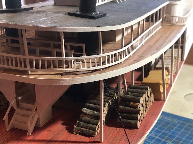
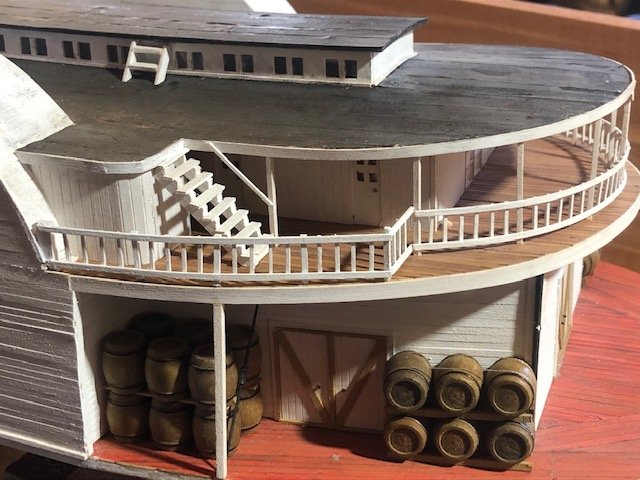
Thanks, John. All kidding aside, we actually know a lot about her cargo as it was almost all salvaged and is on display (or still being catalogued and cleaned) at the museum in Kansas City. She was carrying a lot of whiskey (hence all my barrels) and tons of crates of frontier supplies (nails, boots, tools, farm implements, etc.). She was heading upriver when she sank; any agricultural products would have been carried on a downriver trip. Some cotton was grown in central Missouri, along with other plantation crops like tobacco and hemp; this region was (and still is) referred to as "Little Dixie" given that it had the highest antebellum concentration of slaves and plantations anywhere in the state and was decidedly more Southern than elsewhere; you can still find huge plantation-style houses along the Missouri River in this area.
- 599 replies
-
- 6
-
-
- sidewheeler
- arabia
- (and 4 more)
-
Mark, that's very generous, let me think about it. Another option is just to make a rough solid hull, plank over it, and cover the boat with a tarp. I've read in multiple locations that these were almost never covered, which is why I've avoided that option so far.
- 599 replies
-
- 3
-
-
- sidewheeler
- arabia
- (and 4 more)
-
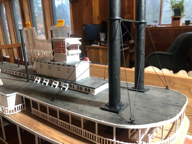
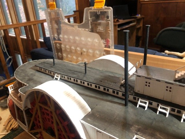
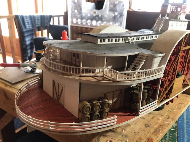
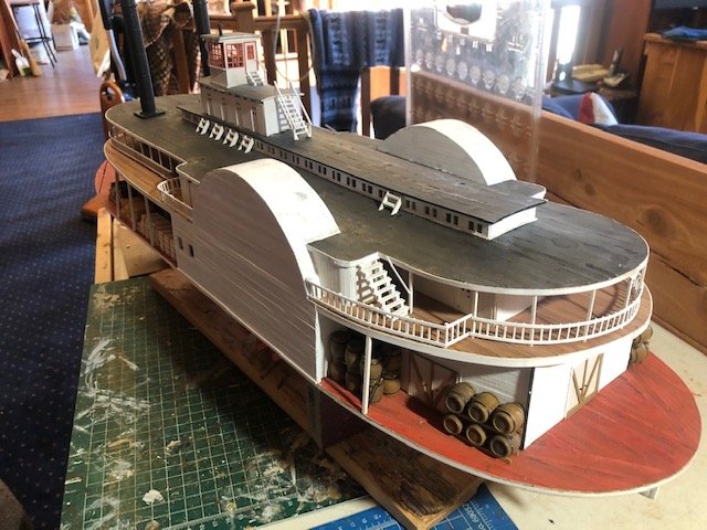
I have tried three different ways of scratchbuilding scale boats and none have worked. Feeling rather frustrated. I just can't get them to form right using pieces small enough to look in-scale; my skills just can't seem to handle detail work at that level and I don't have a feel for the natural shape of a hull. Even a simple john boat is escaping me. I did make some other progress by installing some more details along the superstructure and setting up the rigging for the main chimneys (below). The two small chimneys down the centerline would lead to wood stoves. The two taller stacks are the steam vents from the engines. Two shots of the chimney rigging (below). I used a basic braided line left over from some kit. To make the attachments on the chimneys, I glued some old parrel beads from my revenue schooner. To make the attachments on the deck, I made thin wooden "clamps" (these would have mirrored similar planks below the deck, clamping together over the beams) and drilled small eyebolts into them (also left over from my revenue schooner). The line was white, so once it was tied and glued in place, I painted it black, hoping that would help stabilize it. The knots came out a little coarser than I intended, but they match the overall quality of the build (don't look too closely). I know these are supposed to have turnbuckles but I couldn't come up with a way to simulate these at scale that looked better than leaving them out. I think the next step will be to start placing various details on the bow, such as the steam capstan and the "grasshopper" spars used to haul the boat over sandbars. Then she'll be getting pretty close to finished, other than those danged boats.

- 599 replies
-
- 12
-
-
- sidewheeler
- arabia
- (and 4 more)
-
Mark, I meant the scale of the craft overall. I can know that I need a boat that's X long in inches, but depending on how the parts are scaled it may or may not look right. For example, a boat with parts scaled for 1:48 just won't look right in 1:64 even if it's the right "length". And I can't find any info on scaling from MS; need to check out MK. The scanner idea is interesting but then I have a boat kit I don't otherwise need. For the moment I'm going to keep stubbornly experimenting for myself but I'll keep your idea as a backup.
- 599 replies
-
- 5
-
-
- sidewheeler
- arabia
- (and 4 more)
-
Those kits look really handy, but I'm afraid they'd be out of scale at my 1:64 if they were right for your 1:48; MS doesn't give a scale. I've started dabbling with this but have yet to figure out an approach that works for me. It's harder than I thought to lay out and build a very small boat at this scale.
- 599 replies
-
- 4
-
-
- sidewheeler
- arabia
- (and 4 more)
-
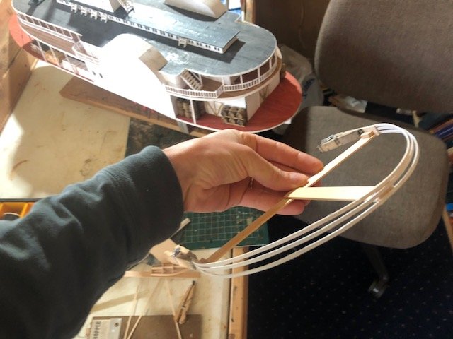
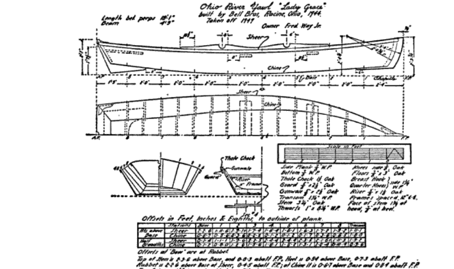
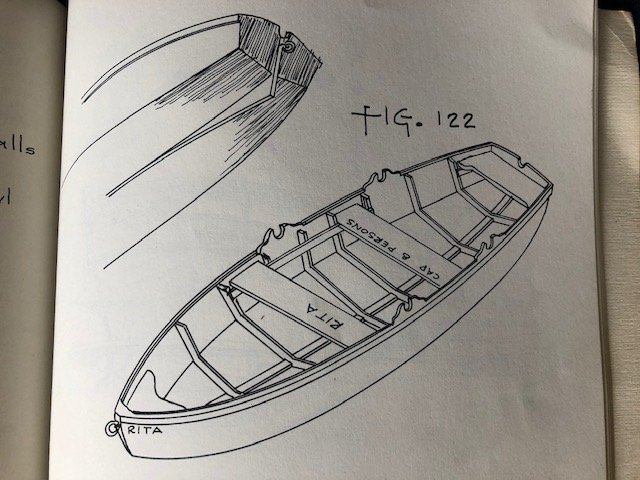
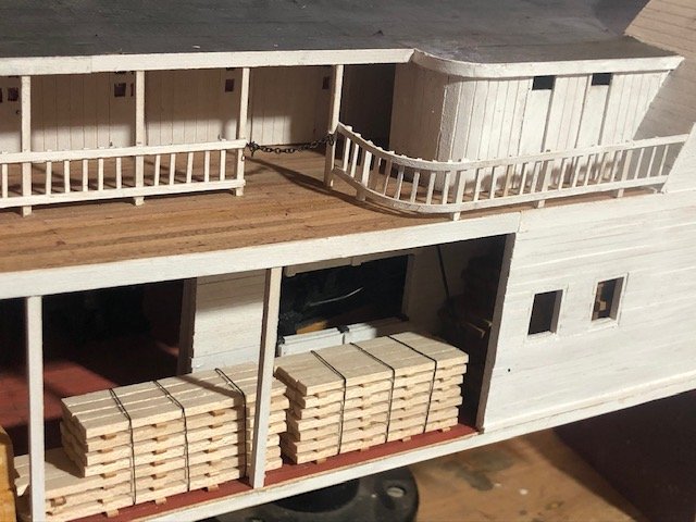
I managed two more steps this week. First was gluing in the chimneys, which was scary as now there's a much larger delicate feature to bump or snag. No photos of this because it doesn't look any different from past test-fittings. Second, I worked on the main deck stern railings. This was difficult because I needed the railings to hold the full curve around the stern without any other support as the boiler deck doesn't extend out over this. Here's an example of what I'm basing this on. So what I did was build a basic jig that would hold the railings in the right curve while I (a) soaked and bent them and (b) painted them, as I've learned the hard way that painting makes thin strips like this lose a lot of their pre-bent curve. This worked really well. After the initial soaking and drying, I painted them in place. When that was dry, I took them off and painted the small bits covered by the clamps and jig; this wasn't enough to lose the curve. Then I mounted three thick posts on the main deck using small pins, one at each end of the railing and one at the very stern. When these were solid, I mounted the railings, then went back in and added smaller spacing posts. Here's the results: I think it came out nicely. Now I'm terrified of bumping the stern. Oh well. I've also started thinking about the two yawls I'll need. These were a pretty distinct design used on the Western Rivers; there was some good discussion of these over in Brian's Chaperon build, such as here and here. Basically I need to build two 16-18' boats with a flat stern and a hard chine (no rounding between the bottom and the sides). In addition to the photos shared in the second link above, I found two relevant drawings of what these craft might have looked like, but these differ in one important respect and I'd like an opinion from the resident experts (look, I'm asking ahead of time for once!). First, drawings of an Ohio River yawl from Howard Chappelle (sourced from Google Books). This has a fully flat bottom from side to side. Second, a sketch of a riverboat yawl from Alan Bates (photo from a book in my possession). This has an angled bottom from side to side: I'm not sure about posting these images as it technically may violate copyright, but I'm also not sure how else to explain what I'm trying to work out about these two designs. Happy to take them down in a moderator thinks it's a problem. Meanwhile, I'd like to better understand the difference between the two and which version might be better for me (and/or easier to build). Any advice/input?
- 599 replies
-
- 13
-
-
- sidewheeler
- arabia
- (and 4 more)
-
That's an interesting thought. I'm feeling that a bit in my current 2.5 year project and could see the value in doing somethinge else, but I also so want to be done! Regardless, well done. Master Korabel seems to do really nice work.
- 77 replies
-
- 5
-
-
- morel
- master korabel
- (and 1 more)
-
Chuck has been affected by the virus-related business closures; you can keep up with his status here; it's a long thread but reading the last couple pages will give you a sense of his current situation. As you don't need the blocks for a while, just keep the idea in mind. I don't remember their cost offhand.
- 950 replies
-
- 2
-
-
- syren
- model shipways
- (and 1 more)
-
Good start, happy to follow along. Depending on your budget, you might consider replacing all the blocks with those made by Syren as they're of really high quality and a joy to work with. Not that you need to order them now, but as a thought instead of ordering replacements from M-E.
- 950 replies
-
- 2
-
-
- syren
- model shipways
- (and 1 more)
-
I'd like to say that I really enjoyed the article on the Coast Guard river cutters, especially given the Yacona's early adoption of desegregated crews. I knew nothing about this bit of history and was glad to learn it.
-
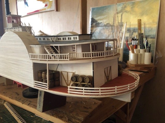
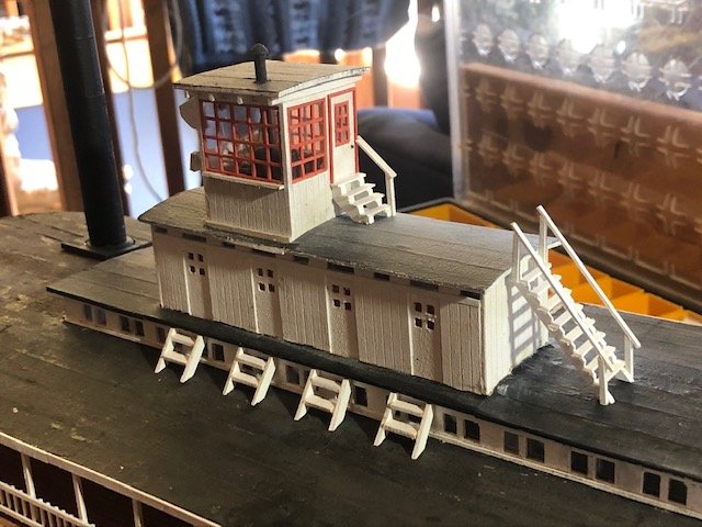
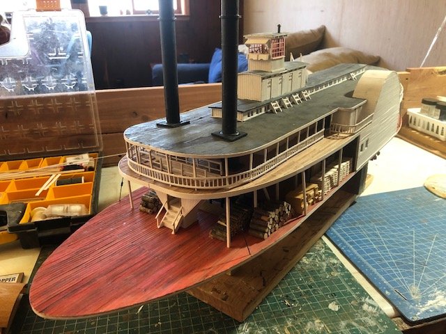
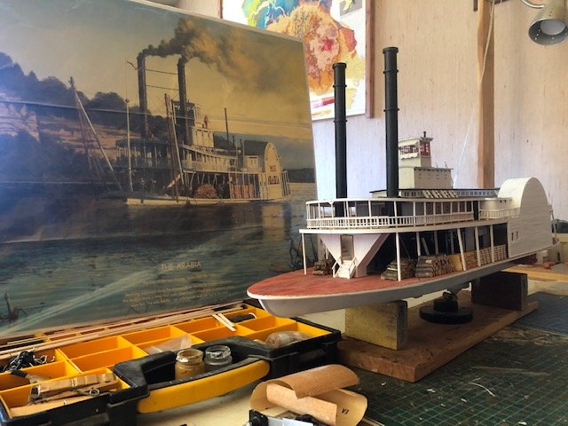
Spent the last two weeks working on various details. The railings on the boiler deck have been giving me nightmares, but I finally figured out a "good-enough" way that works at the level of the rest of the model (representative if not precisely accurate, don't look too close). These were really difficult to bend and shape, especially where they didn't extend between two decks for extra support. I left a gap on either side, forward of the wheels, to allow access to where the boats will be stored. Figured a chain was enough to keep passengers out; this was leftover scrap from a past model: These stern railings were especially tricky: Ladders up to the pilot house and various Texas cabins: A couple broader views: And here's one posed with the painting this model is loosely based on: It's getting ever scarier to handle this model as the fragile details go in. I'm so paranoid about bumping these railings, they were such a pain to do in the first place. And it's just going to get worse...
- 599 replies
-
- 18
-
-
- sidewheeler
- arabia
- (and 4 more)
-
Nice work so far, especially in working around the inevitable mistakes or accidents. The general consensus is that wood glue is far preferable for binding wood than CA is, though the latter has a role in certain applications. Just keep it away from water! I think you said you were bending your planks dry, which might have contributed to one snapping. Soaking them really helps loosen up the fibers so the wood takes the bend easier. Your model is looking very nice, and this is a great way to practice these skills before diving into something bigger. Keep it up!
-
I thoroughly approve of your helpers, as evidenced by my username and photo. You made an earlier comment about certain things looking better from a distance, that's true for most models. Only the true geniuses among us can make things that look great in close-up photos!
-
Yeah, that was probably a little harsh. Feeling kinda edgy. Not a criticism of anyone building the kit, just a frustration that such a wildly unrealistic kit is the only "entry level" option available. As for Model Expo, I hope they have the resources to wait this out and come back online whenever that becomes possible.
- 133 replies
-
- 2
-
-
- chaperon
- model shipways
- (and 2 more)
-
If only we could replace all the awful King of the Mississippi kits with this one...
- 133 replies
-
- 2
-
-
- chaperon
- model shipways
- (and 2 more)
-
That's fantastic! Love the googly eyes, you could've donated the model to a Disney movie.
- 133 replies
-
- 3
-
-
- chaperon
- model shipways
- (and 2 more)
-
I'm working on doing a better job of checking out the logs of everyone who pays attention to mine. This is an amazing build that I'm sad to have missed so far.
-
Cool protoype, I've read nothing but good things about Master Korabel. I was a Russian major once upon a time and would love to be of help, though at this point I suspect Google is just as effective in most settings. Let me know if otherwise!
- 77 replies
-
- 5
-
-
- morel
- master korabel
- (and 1 more)
-
¡Bienvenida a nuestra comunidad, Sergio! Please start a separate build log where you can share your pictures, and tell us here when you've done so. I hope you continue to enjoy this really fun hobby.
-
Looks like a fun project, keep us updated.
-
Your progress looks great so far. I love the look of these vessels. Hope you'll keep posting on your progress.