Cathead
-
Posts
3,550 -
Joined
-
Last visited
Content Type
Profiles
Forums
Gallery
Events
Everything posted by Cathead
-
 Thanks, John. If there's interest, I'll do another diagram from the bow view once the port side is done.
- 599 replies
-
- 2
-

-
- sidewheeler
- arabia
- (and 4 more)
-
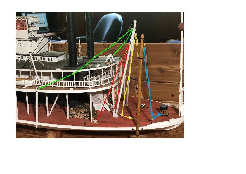
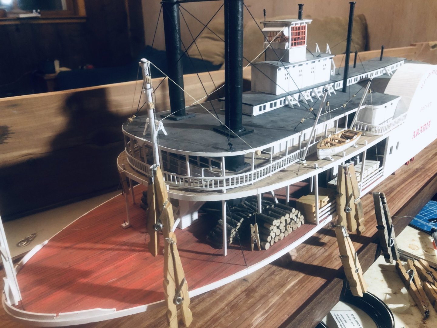
Starboard rigging is done. This took quite a while, as there were so many details to work out regarding just how some of the lines should be run. I also had to make a lot of little rope coils. Final arrangement of starboard yawl: Final arrangement of starboard spar and grasshopper pole: Below is a diagram showing how all the lines work. I thought this might be of interest since (a) they’re hard to follow in photos and (b) it might not be obvious to many folks. I can’t promise this arrangement is “right”, but it’s based on looking at lots of photos and working out for myself what might make sense operationally. Anyway, as already determined, there was no one way of doing almost anything on these boats, so there’s a lot of modeler’s discretion. Note that I added the capstan as well, which would be needed to operate many of these lines. Green: Lines controlling the spar/boom. Adjusting these allows this to be raised, lowered, or swung. One line goes from the tip of the spar to each side of the superstructure, crossing in the middle. Note that the port spar isn’t fully rigged yet, so ignore the lines leading there as they’re not tightened or finalized. Red: Lines for a cargo hoist. Lower end is a dangling block with a cargo hook, currently hooked into a ring on the post closer to the central stairway. Took this idea from a drawing of the Far West and the previous discussion regarding having a way to move regular heavy loads around. This runs up to a block hung from the spar, then down to the cleat near the firewood pile. Can be run over to the capstan if needed. Yellow: Lines suspending the grasshopper pole from the regular spar. These let the grasshopper pole be raised or lowered while dangling from the spar. Runs from a cleat on the deck through several blocks. Should be used with the capstan. Blue: Lines allowing the boat to be hoisted over a bar using the grasshopper pole. Currently rigged from the capstan through a block on the deck, then up to the top of the grasshopper pole. When this is tightened, the whole boat can be lifted on that pole. I have this rigged with the grasshopper ready to deploy, hanging from the side. The lower end could be roped or chained in place; I liked the look of a chain. I found a note in Steamboats on the Western Rivers stating that the poles were "usually carried in an upright position on the main deck at either side just forward of the upper works", as done here. Using the grasshopper system would involve the following steps. It's my impression that both grasshoppers were used simultaneously, presumably by wrapping both lines around the capstan, but I'm not 100% sure of this. Swing the pole(s) over the side (green lines) if not already dangling there, as it is here Let pole(s) drop to river bottom (Ioosen yellow lines), presumably not very far if the bow is grounded on a sandbar Tighten blue lines using capstan. This hauls the whole bow upward since the pole(s) is(are) jammed into the river bottom Put engines on full forward, forcing the boat forward in a lurching up, sideways, down motion, like someone swinging over the top of crutches. Repeat as necessary until far enough over the bar that the engines can drive the boat forward. A given cycle might only move the boat forward a few feet and need to be repeated many times to get over a bar. Stow the pole(s) again by reversing steps 3-1. Steamboat hulls had to be very flexible for this to work; a hard keel like that on a sailing ship would snap during this operation, but the long steamboat hull could flex in multiple directions like a snake. This was one purpose of the iron hog chains running along and across the hull; these braced the hull and allowed for such flexing. Steamboats on the Western Rivers also notes that one boat in 1867 had to set spars 132 times on a downriver voyage from Montana to Missouri, with the crew in a state of near-mutiny by the end. At least the Arabia had a steam capstan; before this development grasshoppering involved lots of crew turning the capstan by hand, rather dangerous given the huge tension on the lines.
- 599 replies
-
- 16
-
-
- sidewheeler
- arabia
- (and 4 more)
-
New Young Model Builder from Minnesota LOOKING FOR ADVICE
Cathead replied to Kenna's topic in New member Introductions
Kenna, Good questions. I would say that any standard set of exacto blades should work fine; I use different shapes for different purposes but you don't need anything fancy. Sharpness is the most important factor, as a dull blade can crush or deform the very thin and fragile wood you'll be working with. As for glue, I use standard carpenter's wood glue for all my models, which is pretty benign. I hate fumes and work within my living room. This is all you should need for everything except maybe rigging (I use small droplets of CA to set knots). Although there is some debate about glues, it seems generally true that wood glue sets and holds wood especially well and should not degrade over time (some have suggested that CA does not age well). Wood glue is also easier to keep where it is put, while CA has a bad habit of soaking into wood and discoloring it or otherwise altering its appearance and performance. Moreoever, wood glue is easy to clean up from and to dissolve if you need to undo a mistake. As you're trying to avoid fumes, I'd also note that paints vary widely in this regard. I've found that Model Shipway's line of paints are very benign in terms of fumes and I use these exclusively. As with wood glue, I can work with these in my small living room and not bother myself or my wife (both of us are very sensitive to chemicals). I'd suggest reading through a few of the tutorials presented elsewhere on MSW regarding basic skills in hull preparation and planking before you get started. This isn't always intuitive even to people otherwise skilled in woodcraft (it wasn't to me when I got started) and understanding the concepts may really help you. Kit instructions often assume a certain level of knowledge on the builder's part that can be frustrating if you proceed blind. I know we're all trying to "tell you what to do", so please remember to have fun figuring it out for yourself, too! We're all very excited for you and just want to ease your journey. I hope you'll consider starting a build log here on MSW to track your progress with the Golden Hind kit, where you can continue to ask questions and share your progress. It's a really rewarding way to build a model. I couldn't have gotten started in this hobby without the advice and support I got from folks here on MSW. -
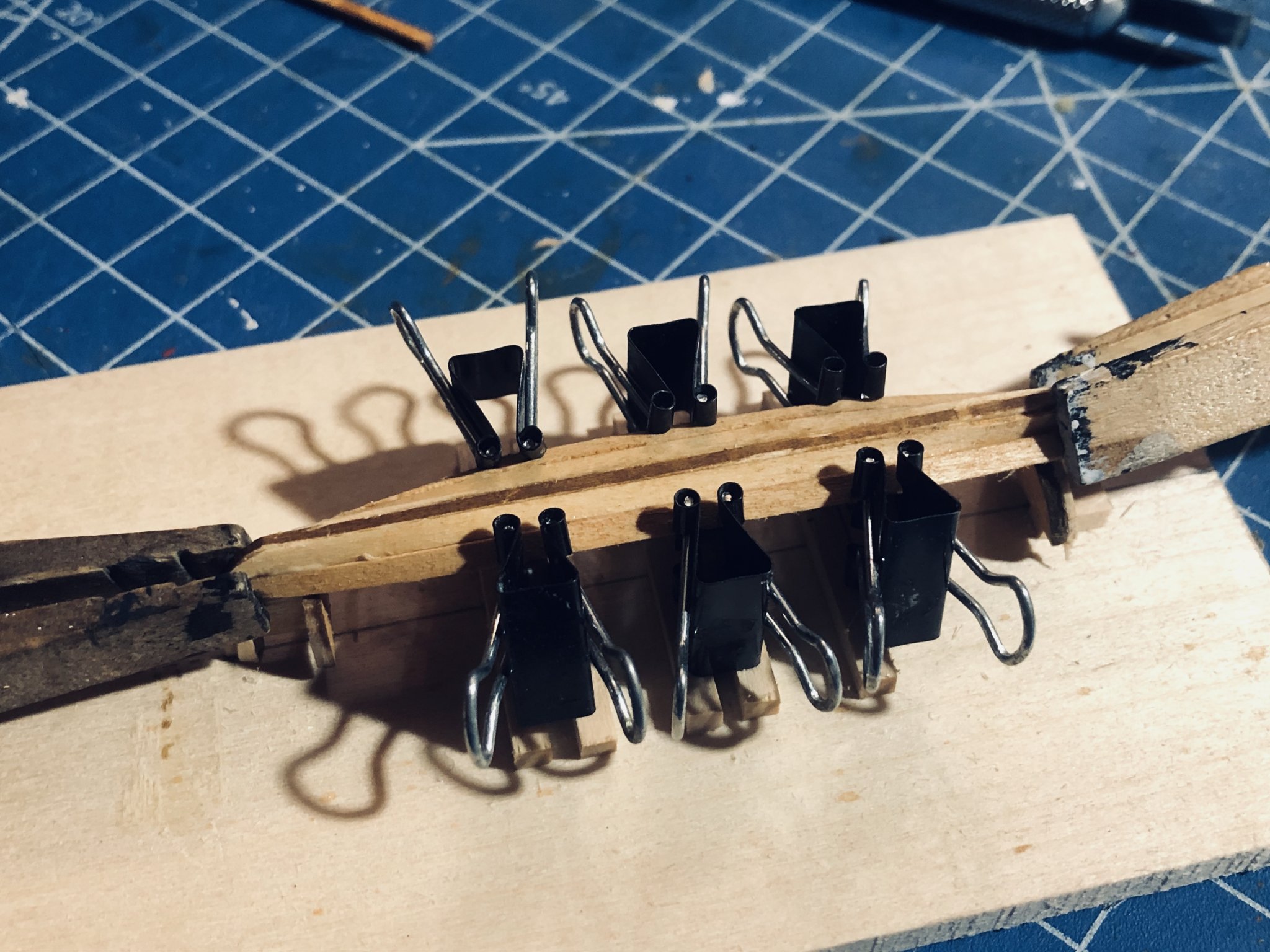
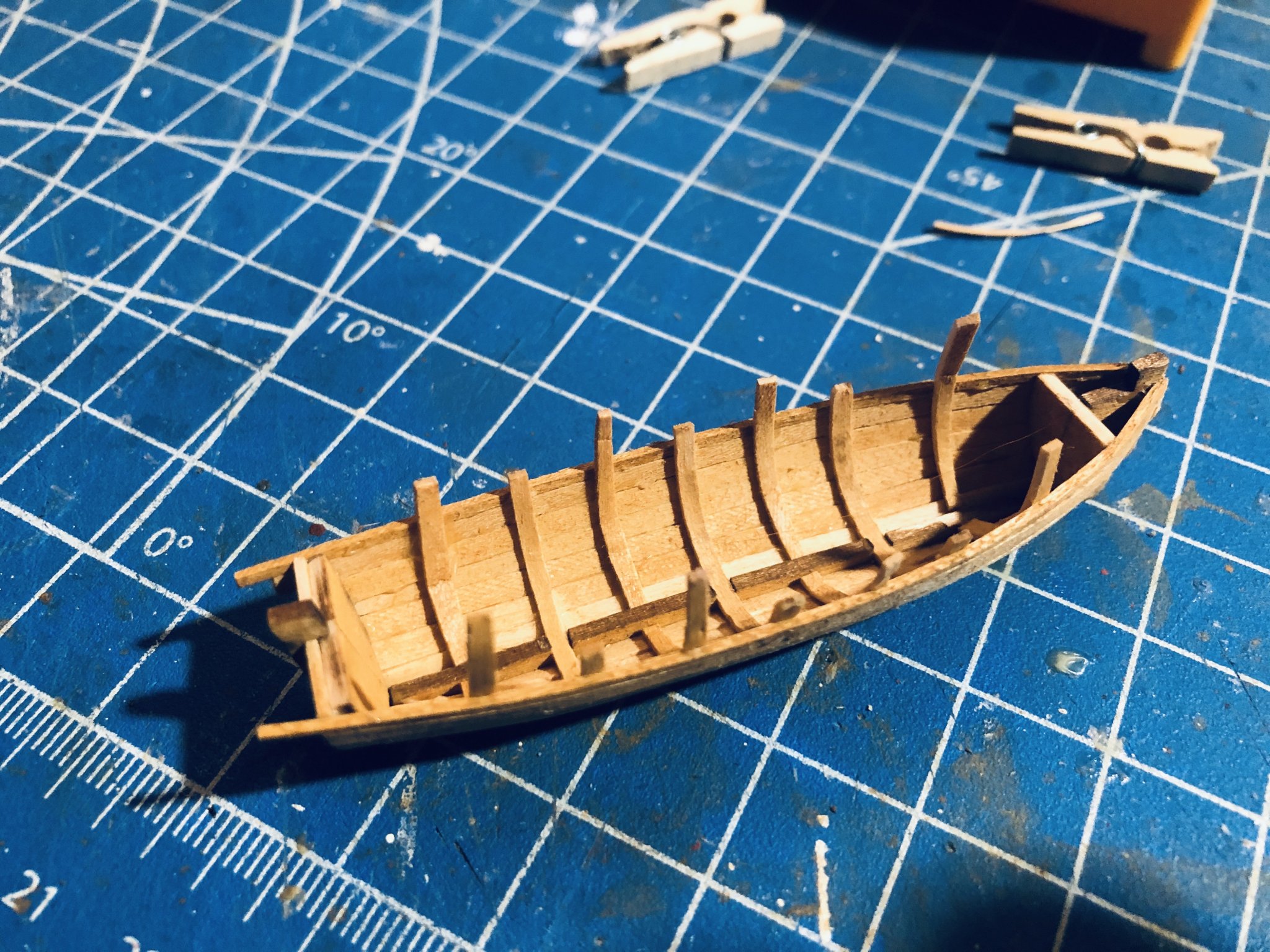
EDIT: re. ccoyle, I did mean wood glue, though good point about the slowing-curing CA. I personally hate using CA both because of the fumes and because of its tendency to ruin wood as you noted. It's fine for setting knots but I really don't like using it on wood as it never seems to stay where it's put. I've read some people talk about using wood glue for most of the joints and a few spots of CA just to hold the plank in place while the wood glue dries, but have never tried that. Original answer: There are a variety of very small clamps that can be purchased inexpensively from various sources. You can also make your own from small binder clips. In addition, I find that normal carpenter's wood glue sets up pretty fast (within a few minutes) when it is spread thinly between two pieces and held tight. This is especially true if you run a thin bead of glue along the plank edges, not just at the ribs. I can set a plank on a small boat like that with such glue, hold it in place with my fingers, and let go after a short wait. Fingers are the best clamps possible as they're infinitely adaptable and don't mar the surface. I still use clamps when I can to make life even easier, but I don't mind using fingers, especially if I just watch or listen to something while working to occupy my mind during the wait. If using wood glue, you should let it cure longer before stressing it, but it'll hold a plank in place pretty quickly. This works best if you soak and pre-bend the plank so there's less tension on it. See my recent build log for two 3" boat kits from Model Shipways for ideas and the following photos: Note the mini-clothespins in the background here, these are very useful: Might not work for everyone, just sharing how I've done it.

-
Wish I had any insight to contribute. Maybe contact a mod to see if NRG has more contact info than is publically available?
-
Fantastic. I'll be eagerly following along, though I don't know much about these vessels so won't be of much help. I have a lot of family an hour from Vicksburg and it's a really impressive place to visit for many reasons. Thanks for sharing this build with us.
-
I think you're the only one that can answer that, given the specific personal context of why you're doing this and what the model is intended for.
-
New Young Model Builder from Minnesota LOOKING FOR ADVICE
Cathead replied to Kenna's topic in New member Introductions
Just ask Gustavus Adolphus. -
New Young Model Builder from Minnesota LOOKING FOR ADVICE
Cathead replied to Kenna's topic in New member Introductions
How long a model takes partly depends on how much time you have to devote to it. If the two of you are in lockdown with little else to do, or plan on focusing on this as a primary activity for a long summer vacation, it won't take you hearly as long as I suggested. But others, even retired folks, can take years to build a single model depending on their time and abilities. I'm just pointing out that lots of newcomers to wooden kit building underestimate how complex the process is; it's not the same as basic plastic model building where you just follow steps gluing preformed pieces together. If your goal for the ordered kit is just to learn from it, have at it and have fun. Certainly the fact that you've built canoes gives you a big head start in terms of understanding something about how wood bends and the complex geometry of curved hulls. Now that you have the model (or will soon), I'd say give it a try and see how it goes; from there you can decide how to balance that project and your real goal. If you feel like it's too much, set it aside and try a small dory instead; you can always come back to the more complex model when you feel more confident and experienced. My responses (and those of others like Bob) are informed by the heartbreak of seeing too many new modellers jump in over their head, get frustrated, and quit the hobbby again rather than taking the time to develop their skills and work up to their dream project. It's probably overwhelming to gets lots of different advice; we all have different perspectives but we all care a lot about helping newcomers to this beloved hobby of ours, especially younger folks. -
That makes sense too, especially as my version looks more like sockets than hinges!
- 599 replies
-
- 2
-
-
- sidewheeler
- arabia
- (and 4 more)
-
New Young Model Builder from Minnesota LOOKING FOR ADVICE
Cathead replied to Kenna's topic in New member Introductions
Ron & Kenna, I think it would be helpful to clarify (to yourselves and those here) what level of detail you're trying to achieve, as you've partially done above. Until I saw Bob's response, I was planning an answer asking how accurate you were trying to be. For example, you could make a basic representative galleon with highly simplified details that would look cool, but without getting bogged down in "reproduction". A lot of folks here tend to think that model building inherently means super-detailed and highly accurate, but it doesn't have to be that way, and you shouldn't be discouraged by the false idea that model building is museum quality or nothing. For what I think you're trying to achieve, I think you're on the right track. You're clearly describing a large (but not people-carrying) vessel that's fun to play with in a lake but isn't meant to be a detailed replicate. Given that, I'd think upsizing plans is a reasonable idea as long as you're up for adapting them to your intended design. That being said, the smaller model may actually be harder to build because it is intended for builders making super-detailed accurate models and those take a LOT of skill that takes time to develop. If you don't care about a level of accuracy involving the actual ribs (and I suggest that you shouldn't), Bob's right that you may want to think of this as a skiff tricked out as a galleon, even if you do build it from scratch rather than grafting on to an existing boat. If you want to use a model to practice, you might be best off with a simple model (something like the beginner skiffs or ship's boats sold by BlueJacket or Model Shipways) that would teach you the rudiments of hull shaping, planking, etc. The Dusek model may prove more of a distraction than a guide because it may take you years to complete when that isn't really your goal. Just my two cents. I've never done something like you're attempting, but have taken the journal from beginner to moderately skilled builder, and am thrilled that you're (a) interested at all and (b) asking questions and learning rather than just diving in headlong. I hope we can give you all the encouragement and help possible in this very cool project. -
Brian, that is indeed what I simulated, except I didn't make a full socket. They're actually mounted on wire pins inserted into the block below. I wouldn't be surprised if they were actually on hinges (to minimize sideways movement) but I don't know, wasn't sure how to simulate that accurately, and this was good enough for my purposes. I wanted them to move so I could adjust them to a final tension, so needed something flexible (not just glued in at a certain angle). As you said, it's really hard to figure out and I just went with modeller's license on this one. Technically the base wood is eastern red cedar, which is really a juniper species rather than a proper cedar. It's everywhere here and you must have a bunch in your neck of the woods, too. The base woods are finished with wood oil, and I agree I really like how the cedar color complements the red/brown tones of the model. The swirling coarse grain and knots evoke river water, too, at least I think so.
- 599 replies
-
- 2
-
-
- sidewheeler
- arabia
- (and 4 more)
-
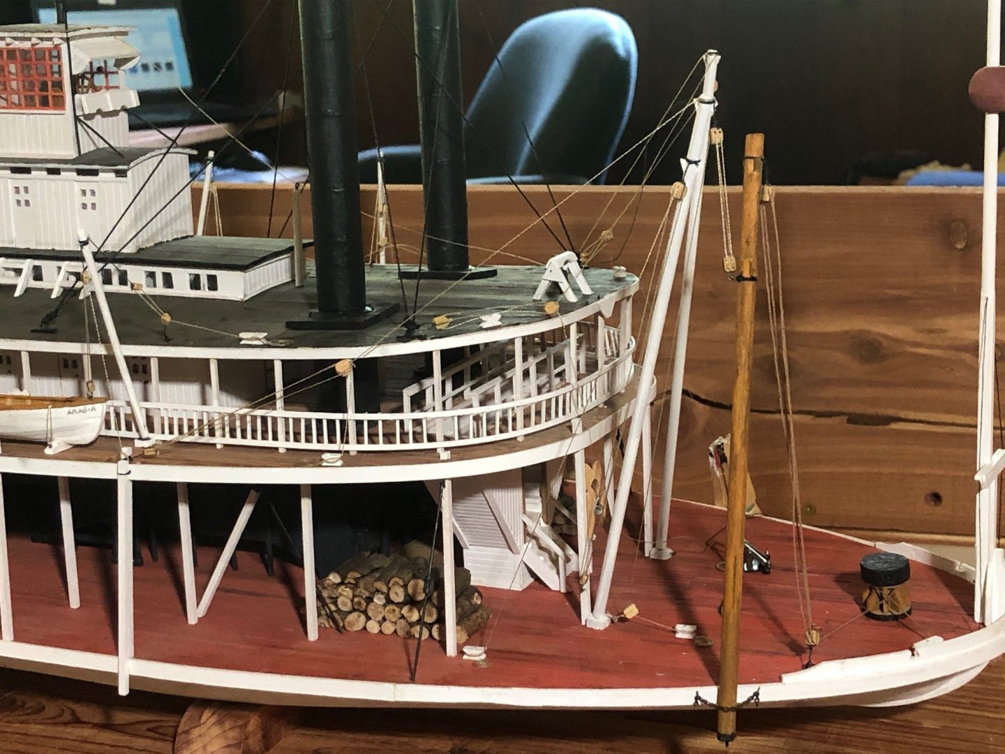
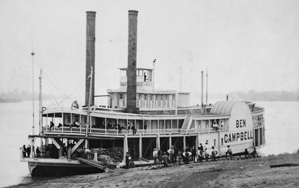
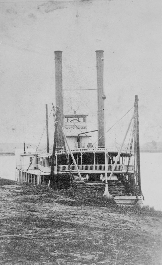
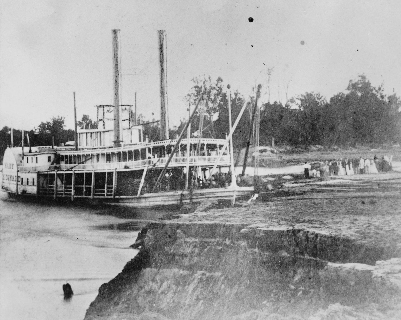
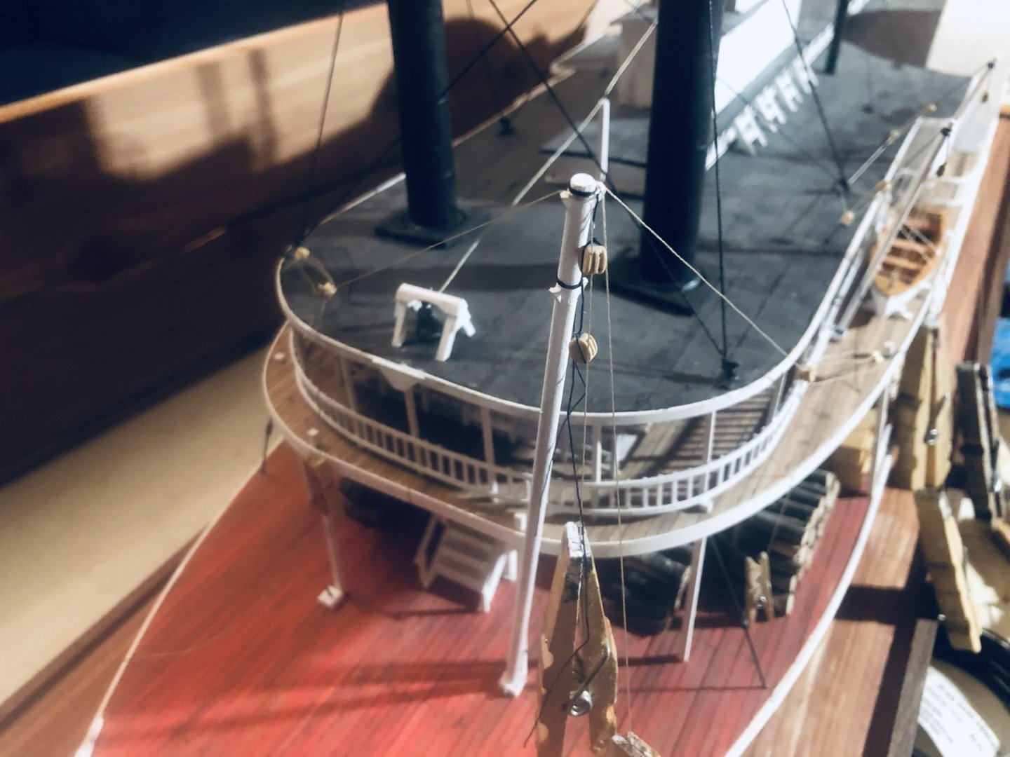
Steve, good eye and good question. Yes, I want them rigged vertically as if she's navigating in the middle-upper Missouri and needs them at a moment's notice. I think you're referring to the jackstaff (tall pole on the bow), and I agree that the rigging lines I have there there would get in the way of resting the grasshopper poles on those jackstaff crosspieces. But it seems that different boats stored their poles in different ways. Based on past discussions in this thread, the Ben Campbell seems to have rested them horizontally on crosspieces on the jackstaff, like this: In this approach, you're right that any rigging on the jackstaff would get in the way. But the Mary McDonald didn't have a cross-wise brace on the jackstaff and had rigging lines running along it. Instead, she seemed to simply tilt the grasshopper poles back a bit and rest their ends on the deck. See below: I'm not sure what she did if/when she needed to use the spars as loading cranes, maybe just set the grasshopper poles on the deck or something, or maybe they just swung out with the spar. But as I'm using the Mary McDonald as my closest reference, and I want the grasshoppers displayed deployed, I went with this arrangement. One difference between these arrangements might be the area of operations. The higher up the Missouri you go, the less likely you're going to be handling heavy cargo with the spars and the more likely you're going to need the grasshoppers. In addition, the higher winds and less cover mean you need more rigging to support things like the jackstaff. So to me, the Mary McDonald looks like she's set up to be an upper-river boat emphasizing regular use of the grasshoppers, while the Campbell looks like it's mostly operating on the lower river and has grasshoppers stowed for occasional use. I want my Arabia to look more like the former, so will emphasize grasshoppers at the ready. This is all just my theory, but it seems plausible to me.
- 599 replies
-
- 6
-
-
- sidewheeler
- arabia
- (and 4 more)
-
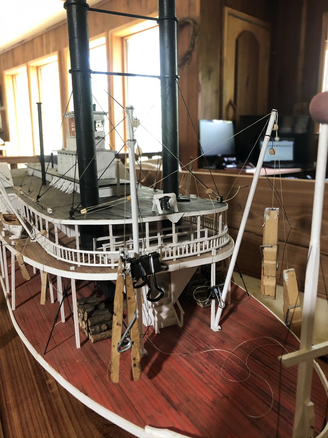
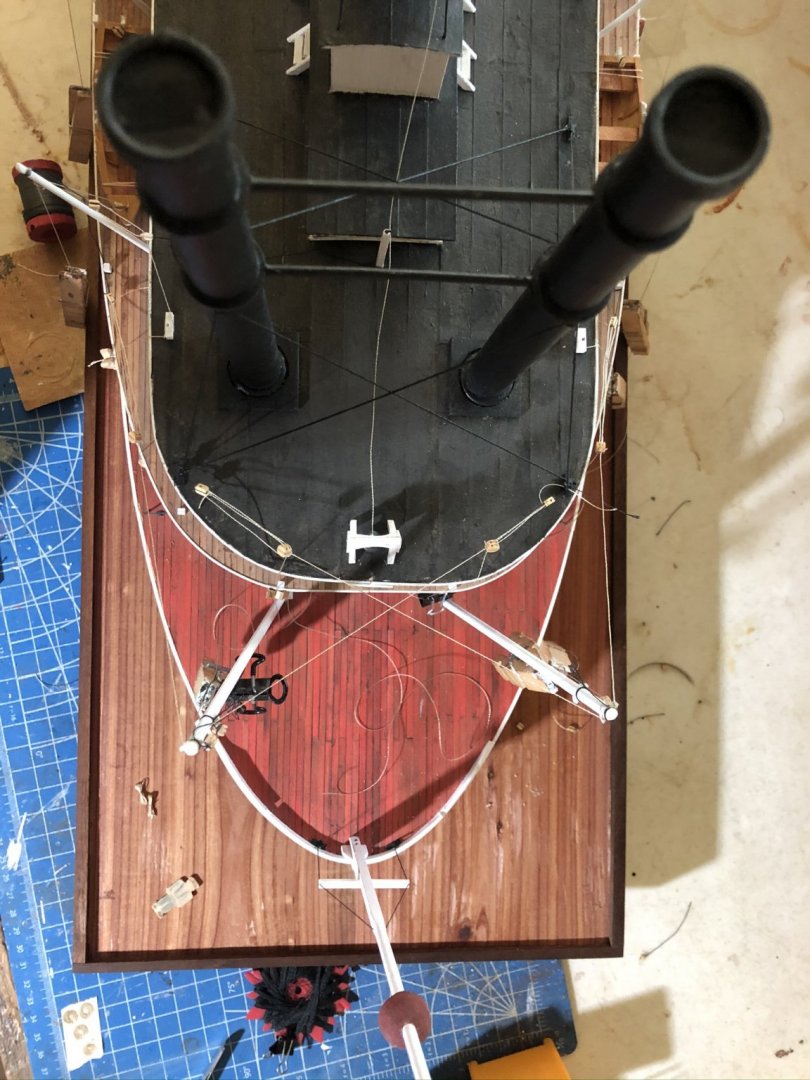
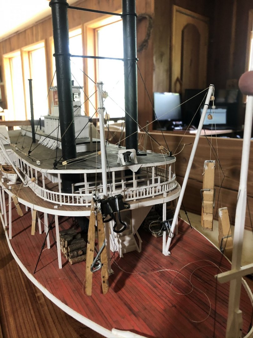
The starboard rigging went a lot faster this morning, likely because I'd spent much of yesterday figuring out how to do it on the port side, whereas this time I just had to copy what I'd done before. I feel like photos really struggle to capture rigging because the lines are so thin and the three-dimensional framework doesn't translate well into a flat photo. Overhead view of the spar rigging. Two lines lead to the tip of each spar, controlling how it moves around the deck: Here's another view of this: The loose blocks hanging off the spars are for rigging the grasshopper poles and for general cargo use. These will be rigged next. Starboard boat rigging: All of this is still loose (hence all the dangling weights). I think I have it the way I want it, meaning I can start gluing in knots, but likely not until tonight or later as I have other things to do this afternoon. So here's your chance to comment if something doesn't look right!

- 599 replies
-
- 12
-
-
- sidewheeler
- arabia
- (and 4 more)
-
You all know she's not done yet, right? Lots of rigging still to go. Here's yesterday's progress on the port side: I'm making all the rigging temporary until it's all done. Too much interaction between parts to trust myself to glue in knots until everything is balanced. Plus I've already found two cases where my original plan was wrong and needed to be amended. So there's going to be a forest of clothespins hanging off her for a while. Sharp eyes might have noticed I added a bell to the front of the hurricane deck, with a line run back to the pilothouse. Stick with me, we're getting there. Thanks for all the support, it means a great deal as this 2 year 8 month project rolls on.
- 599 replies
-
- 12
-
-
- sidewheeler
- arabia
- (and 4 more)
-
Thanks Carl, as a former model railroader I definitely considered ordering some "ballast" or other scenic material to use instead as then I could control the particle size, shape, and color. But I ended up liking the natural wood look, especially as all the wood comes from my property. Perhaps I'll make a sediment base for a future model.
- 599 replies
-
- 3
-
-
- sidewheeler
- arabia
- (and 4 more)
-
Keith, great question, and you're correct. Here's the engine layout from way back in this build: Each wheel has its own engine, which could be controlled independently. For really sharp turns, one could even be reversed while the other stayed in forward, almost spinning the vessel in place. This was a major advantage of sidewheelers over sternwheelers. On the other hand, the paddlewheels were a lot more exposed on sidewheelers, so took more damage from debris (sternwheeler hulls were more likely to deflect debris before it reached the paddles). Sidewheels were also less effective at backing the vessels off sandbars (when stern wheels were reversed, they sent a strong wash of water under the hull, helping free it). For these and other reasons, sternwheelers became more common on upper rivers or anywhere the channel was narrow and/or shallow. So it's especially impressive that Arabia made it deep into Montana since its design wasn't optimal for those conditions.
- 599 replies
-
- 12
-
-
- sidewheeler
- arabia
- (and 4 more)
-
Not familiar with this model, but I agree with harlequin, it'll help you set the planks properly and is good practice. There are planking tutorials here on MSW that can help guide you in figuring out how to do it properly.
-
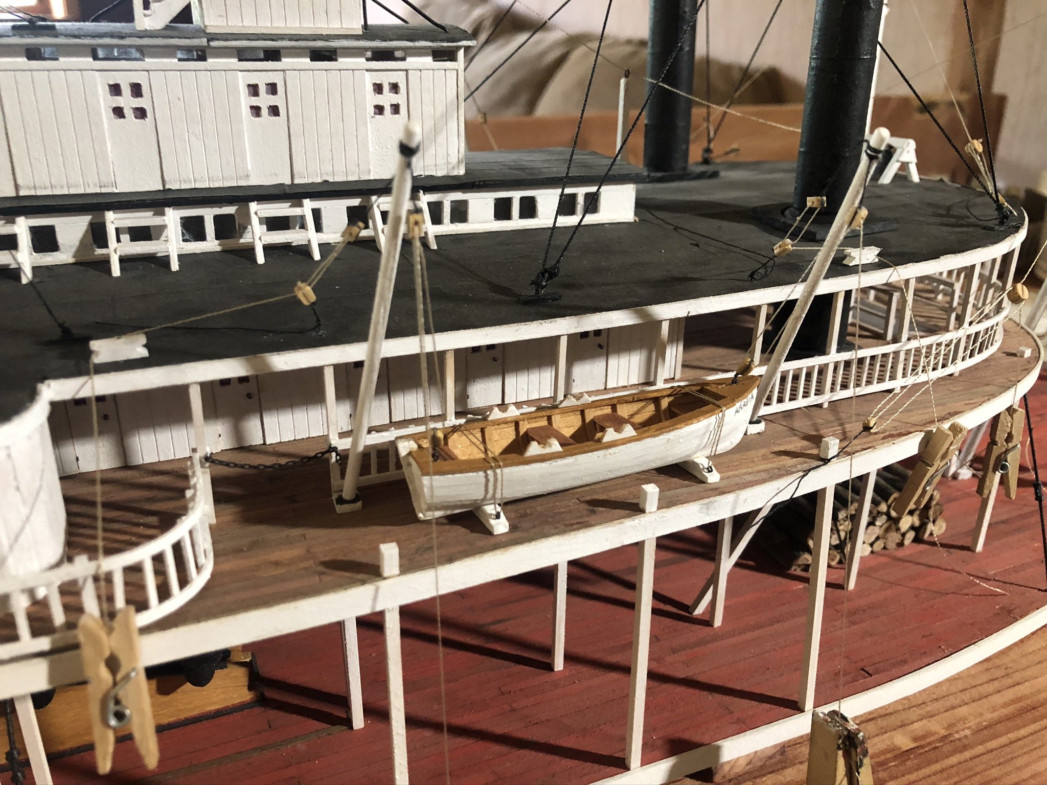
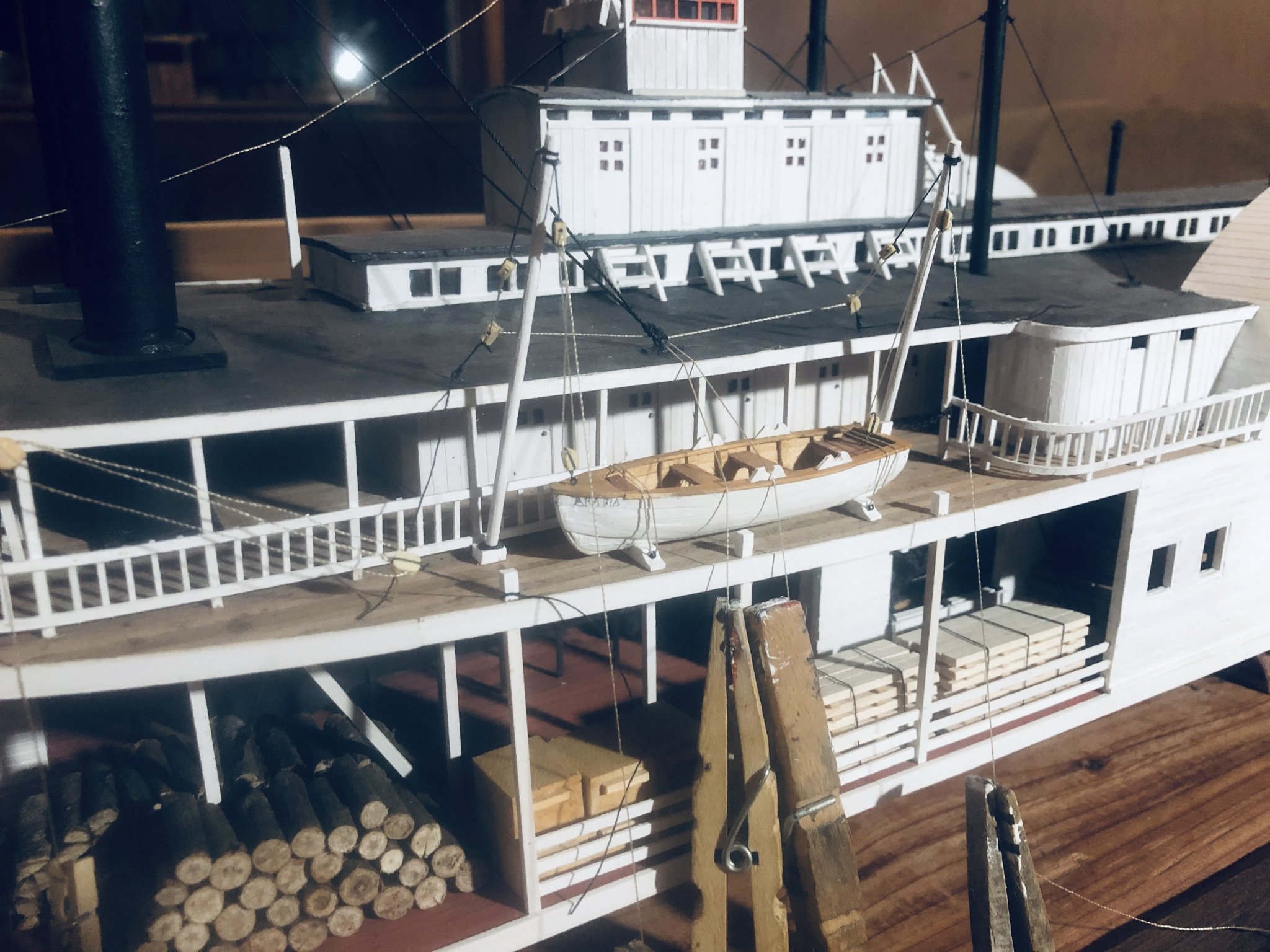
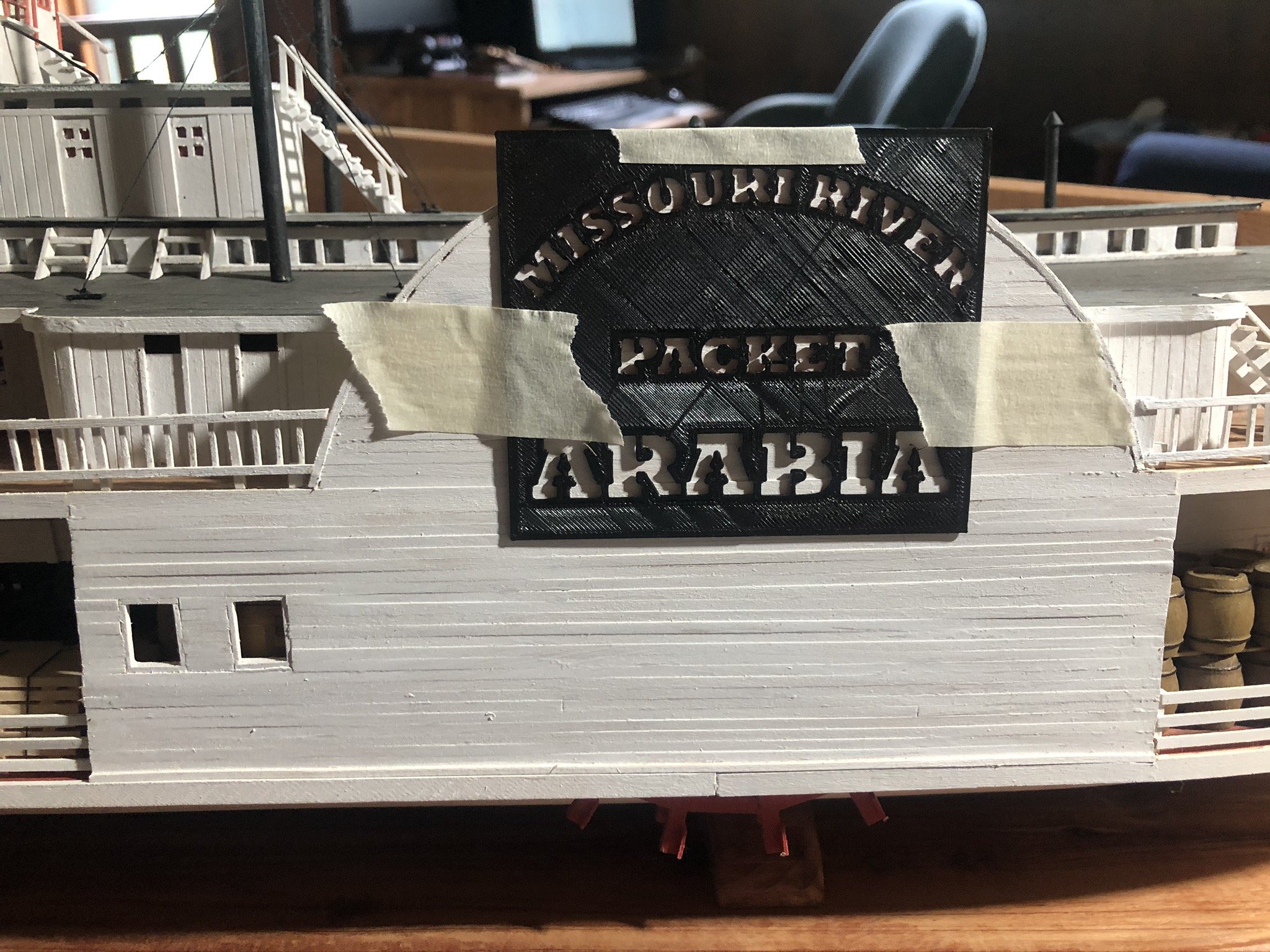
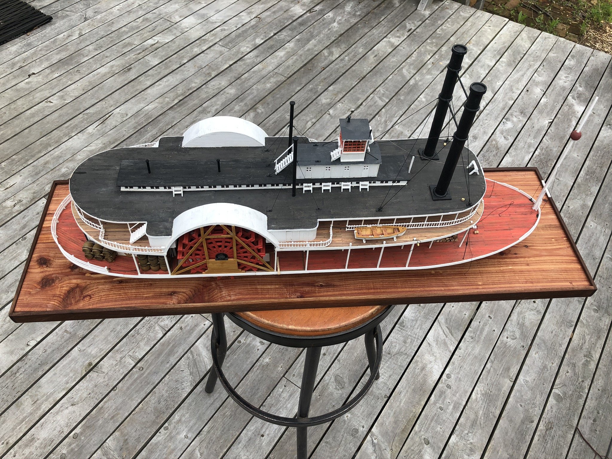
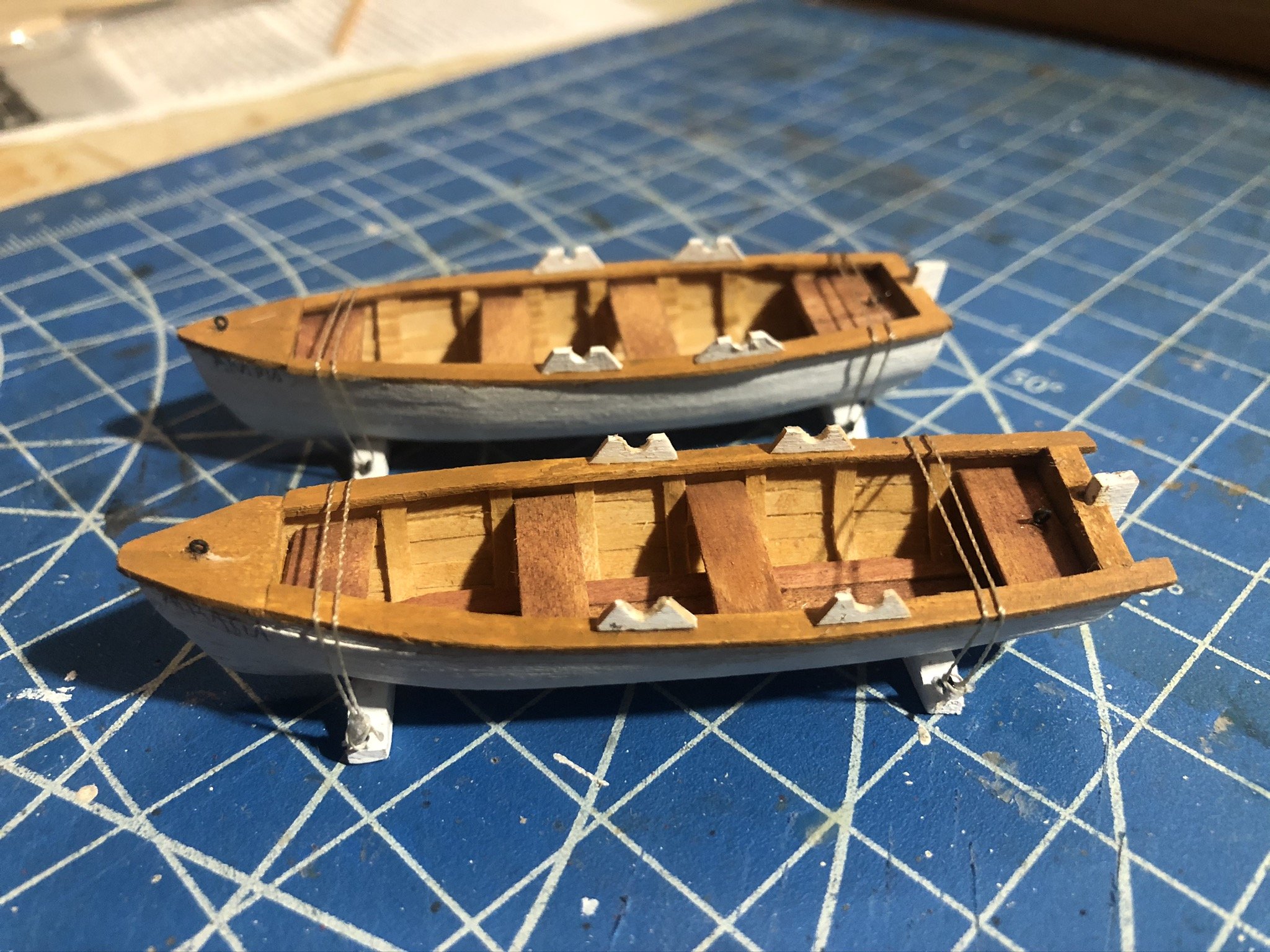
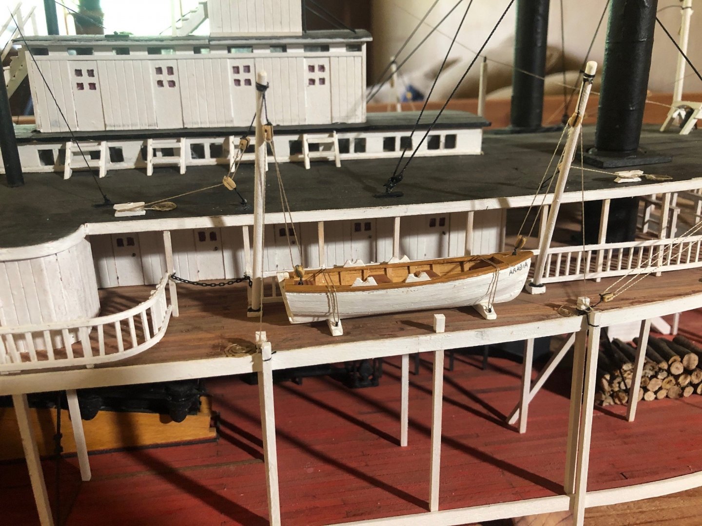
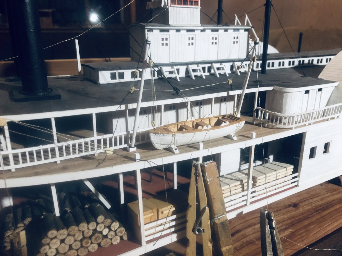
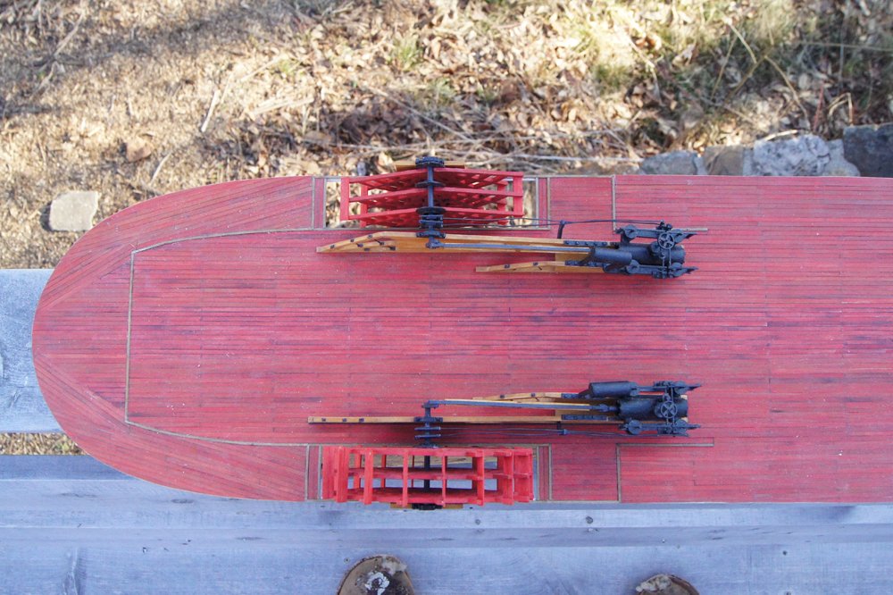
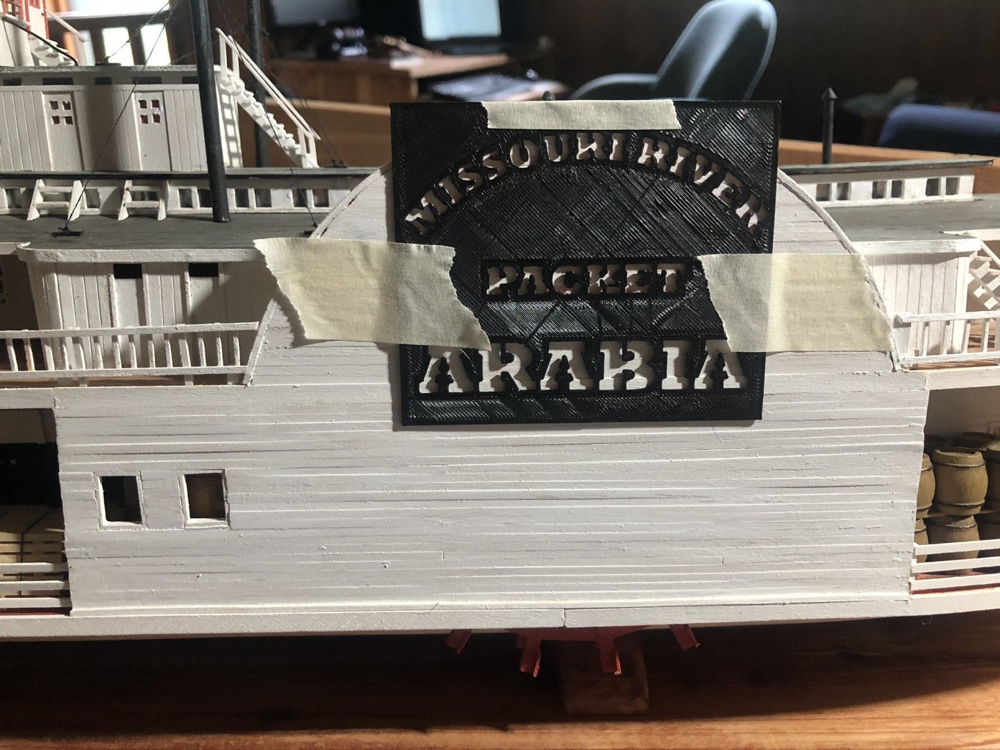
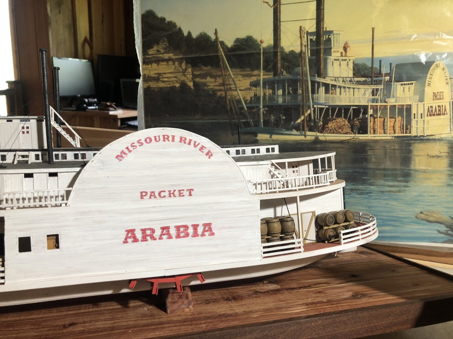
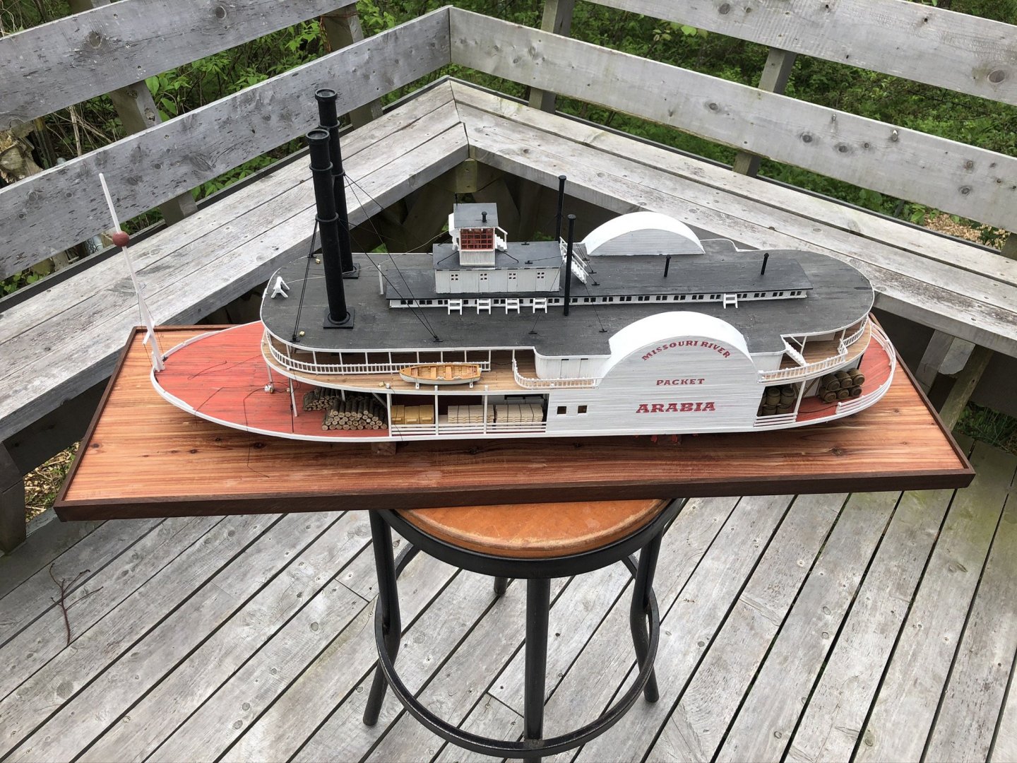
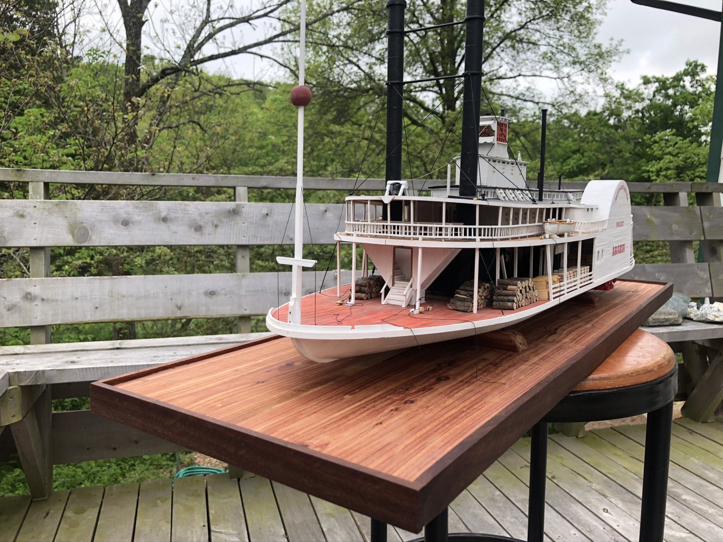
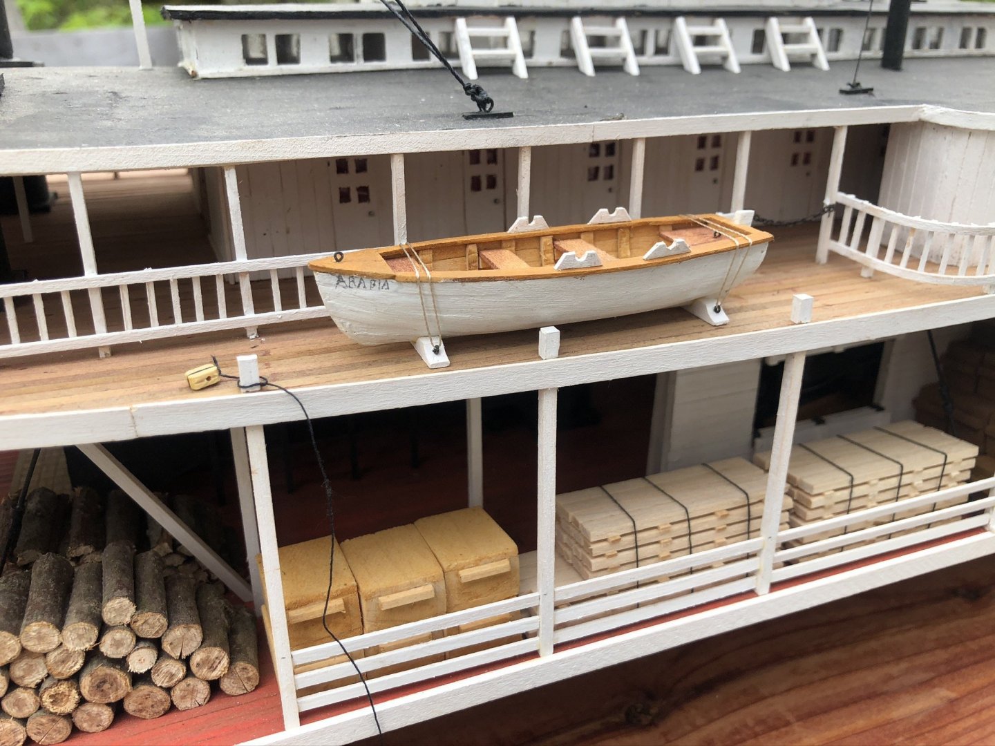
Well, the boats are done; you can read about that journey at the separate build log. Suffice it to say I'll never buy those kits again, but I got a workable result that looks good enough on the Arabia. They're not quite an authentic Ohio River yawl, but they're closer than a bluff-bowed ship's boat or a two-ended whaleboat. Here's one installed with its tie-downs; the davits will be added soon. In order to letter the port wheel housing, I designed a stencil layout and had a friend's tech-savvy teenager make it on a 3D printer. This was a cool mini project and a fun way to involve someone else in the build. Here's the stencil taped on and ready for use: I did some tests first on scrap wood. My initial plan was to use paint, but I couldn't get it to look right, so tried colored pencils and loved the result. So here's the hand-colored final version with red letters and black shading: I think I could have made the lettering a bit larger, it looks too small on the final model although it seemed right during the design process. But I love the way the colored pencil gives an inherently weathered look. Finally, I settled on a stand design after some experiementation. I liked the idea of a sediment-filled base to look like the river bottom, but none of my attempts at sieving natural sediment produced something that looked right to my picky geologist's eye. So I went back to the basic wooden stand idea, based on the one Kurt used for his Chaperon, and came up with what I think is a nice result. This is a Eastern Red Cedar base with Walnut trim, all wood harvested and milled here on-farm. She's now screwed onto the base, awaiting the final details, mostly rigging the davits and grasshopper spars. Really getting close now.

- 599 replies
-
- 22
-
-
- sidewheeler
- arabia
- (and 4 more)
-
Thanks, Mark. I should note that I could have improved them a bit more by using different wood (such as cutting the cap rails out of one sheet to avoid seams) but really wanted to stick with the kit supplies for review/guidance purposes. Someone could in theory buy this just for the frames and design, then use better wood throughout.
- 29 replies
-
- 1
-
-
- ships lifeboat
- model shipways
- (and 1 more)
-
Pretty much all wooden models are held together with glue, even at much finer scales than this. Any treenails/rivets are just for appearances.
-
These little Model Shipways lifeboat kits have serious problems but you can get a decent result if you ignore various parts of the instructions. Here are my suggestions, having built a couple of these. I STRONGLY advise not trying these kits if you’re new to model building or planking; you need to have some idea what you’re doing before tackling these, even with the suggestions below. Frankly, I advise not buying these at all, but you can get a usable result if you insist or are already stuck with one you bought unawares. Suggestions for building these kits, organized by the step numbers given in the kit instructions: 1. Step 1: Assembling the keel a. Don’t bother gluing 1/16” square stock to the keel. It’s not necessary to hold the garboard plank in place and just creates more work trying to sand/file into the curve of the hull. It also gets in the way of laying a nice internal floor later on. b. Similarly, don’t bother bending and gluing this square stock up the curve of the bow. It’s really hard to do and isn’t necessary. Your planks will attach to the bow just fine with sufficient glue; since the internal part of the bow isn’t open to view here, it doesn’t matter if you use excess glue to achieve this and it’s a lot easier than trying to form this piece. c. Thus, Step 1 is just to glue the bow and transom formers to the keel. 2. Step 2: Applying the main ribs a. Don’t bother using rib former #1 unless you really want a bluff-bowed boat. It makes a much sharper curve toward the bow that’s really hard to plank; leaving it out gives you a sharper bow but a much easier planking task. If you want a bluff-bowed boat, try the Master Korabel kits instead as they seem to be of better quality. b. Don’t make the ribs from the 1/16” square stock. Not only is it too thick to bend easily (and will likely crimp into ugly shapes), it’s too large for scale and looks terrible. Just use single pieces of the thinner planking stock; this will take the bend easily and is strong enough to support the planking. c. To help form the curve more smoothly, soak these strips in water, then bend them around a dowel of similar diameter, holding them in place with clamps. Once they dry, they’ll be a lot easier to place into the rib formers, and won’t crimp as easily. This also gives you more consistent curves. d. The planking strips (and the suggested square strips) are thicker than the formers. When you glue the ribs in place on these formers, make sure one side is flush with the former surface (rather than centering them on the former). e. After the glue has dried, use sandpaper or a sharp knife to trim the ribs to the same thickness as the formers. This will create a more accurate width for the ribs and they’ll still be sufficient to support the planking.’ 3. Step 3: Creating the building jig a. Don’t attach the rib formers to the build board unless you carefully mark their exact location based on the notches in the keel. Do NOT follow the instructions in gluing the formers 1” apart on the board, this doesn’t match the boat dimensions! I just glued the ribs into the keel freehand, using my eye and a square to get them straight. Once these were dried, I flipped the assembly over and glued it to the board, adding bracing afterward. In other words, do this in the exact reverse order the instructions suggest (ribs to keel, formers to board, braces to board). I also added braces around the stem and stern, which were very useful for added stability during later sanding work. 4. Step 4: Assembling the hull frame a. I did not glue any 1/16” square strips to the ribs as suggested. These are too thick to bend easily and don’t look realistic anyway. They’re completely unnecessary. I did fair the bow and transom formers, but the thinner ribs need barely any fairing. 5. Step 5: Planking the hull a. Do plank the transom first as suggested, which allows you to ensure that its outside can be sanded fair with the former and accept the planking. The instructions are completely nonsense in stating that planking will require 22 strakes; my boats required 6 strips per side. This may be an artifact of the same instructions being used for lots of different size kits (like the 1” former spacing). b. Do not start planking at the sheer line as suggested in the instructions; this will make life much harder as you try to fit planks into ever-narrow spaces as you go down. Instead, start with the garboard and work your way up. Do start tapering planks at the bow right away so you achieve a reasonable level line of planking as you go; if you don’t, you’ll get Viking-style planking curving up way too much at the bow. You shouldn’t need any stealers if you pay attention. c. Stop planking with one or two strakes to go. It gets very hard to clamp planks at this point because the build board gets in the way. Instead, remove the boat from the board at this point by cutting the ribs right where they enter the formers. The boat will be strong enough to hold its shape and accept the last few strakes, and using clamps from the open top of the boat is way easier. 6. Step 6: Separating the hull. This is mooted by my suggestion in 5c; remove the boat BEFORE planking is completed. 7. Step 7: Filling in ribs a. Make extra ribs the same way you did the original ribs, by bending soaked planking strips (NOT 1/16” square stock) around a dowel and letting dry. Then they’ll be really easy to insert into the hull and cut to length. Like the original ribs, cut or sand these down to a more realistic width. 8. Steps 8, 9, & 10: Mounting the seats and bow platform a. Instead of running a consistent strake all the way around the inside of the hull to support the seats, I just inserted short supports between ribs where the seats and other platforms needed to go. A lot easier and looks fine. b. The bow platform can be installed however you want; at this point the boat is solid and you can adapt the internal details to be whatever you desire. 9. Steps 11 & 12. Mounting the railing and rudder, finishing touches a. I made the railing in the opposite order as the instructions; starting from the bow and working after. I held each ¼” strip against the hull, drew the outside curve with a pencil, then hand-cut the rails. Like the previous steps, all this is discretionary and can be done lots of different ways. I shaped the rails off the model as I wanted to paint/stain them before installation, whereas gluing the strips on first and then carving them is both harder (in my opinion) and makes it more difficult to apply a different color than the main hull later on. b. Otherwise, all finishing touches are builder’s discretion. You’re past the hard part, do what you like. This post is now linked from the updated first post of this thread, along with a few pictures. Hope this is helpful to someone in future.
- 29 replies
-
- 5
-
-
- ships lifeboat
- model shipways
- (and 1 more)
-
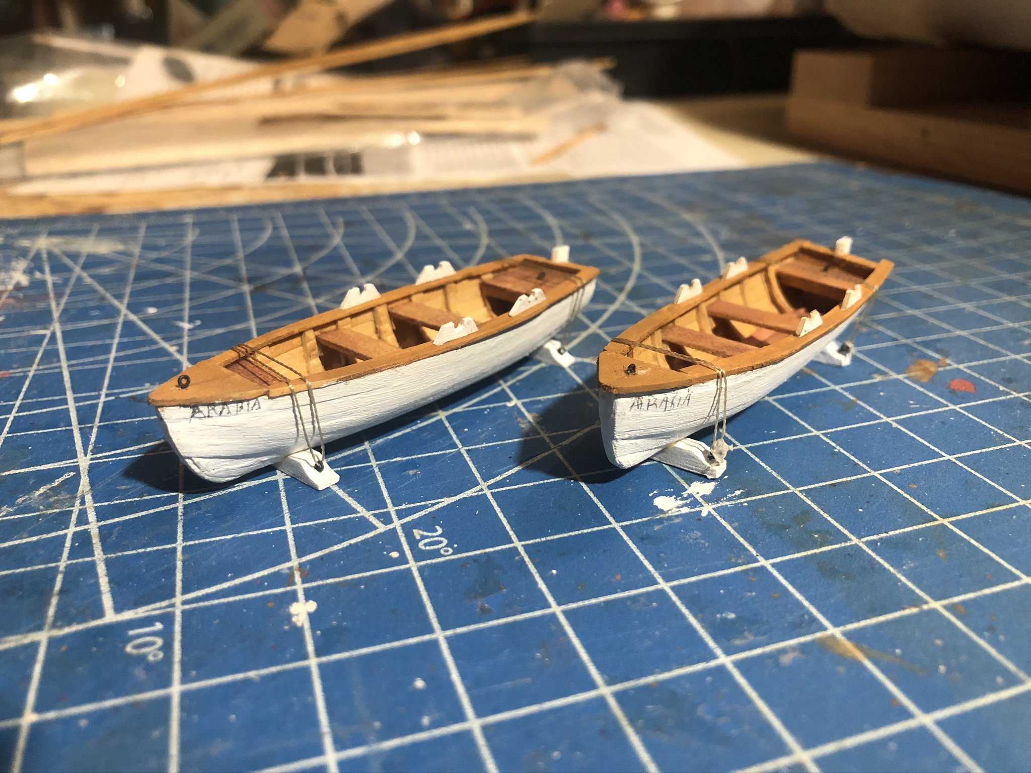
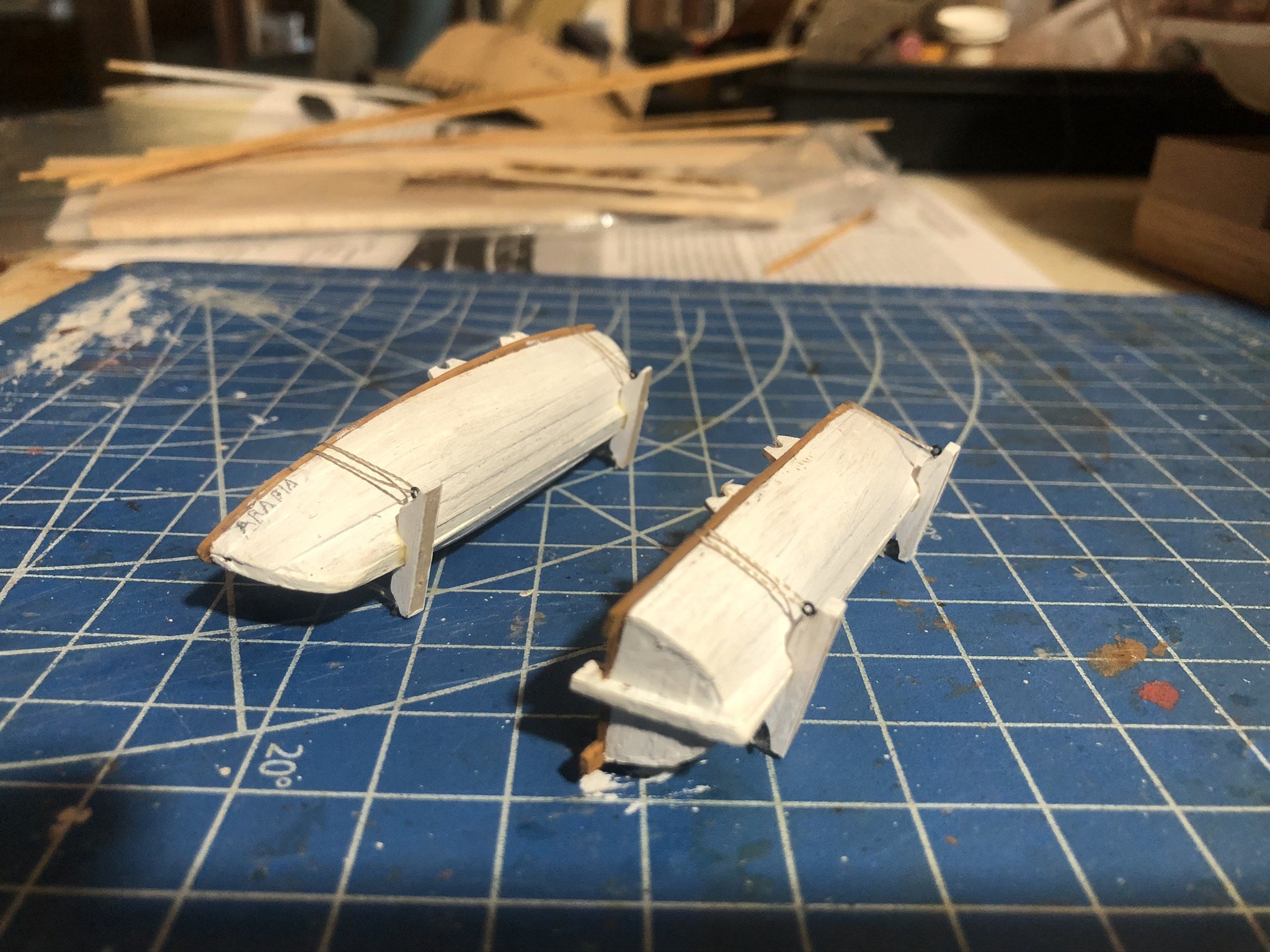
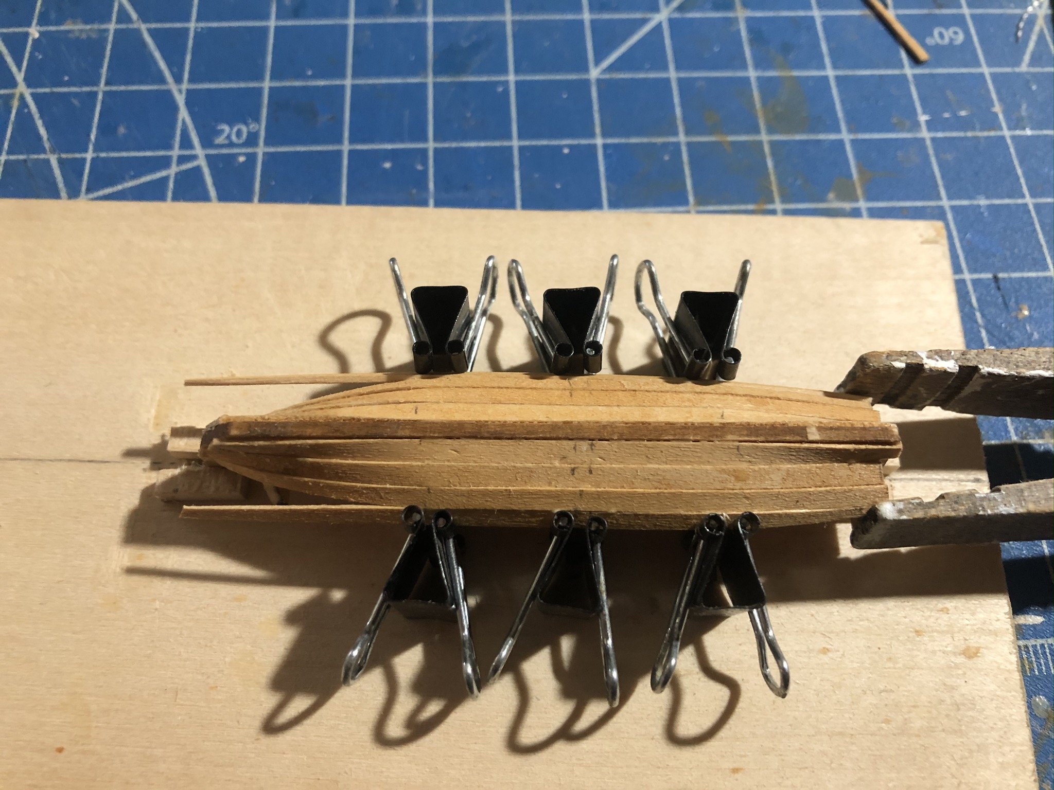
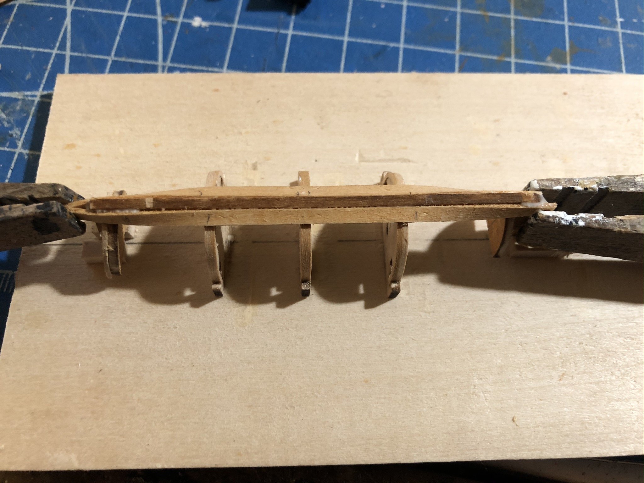
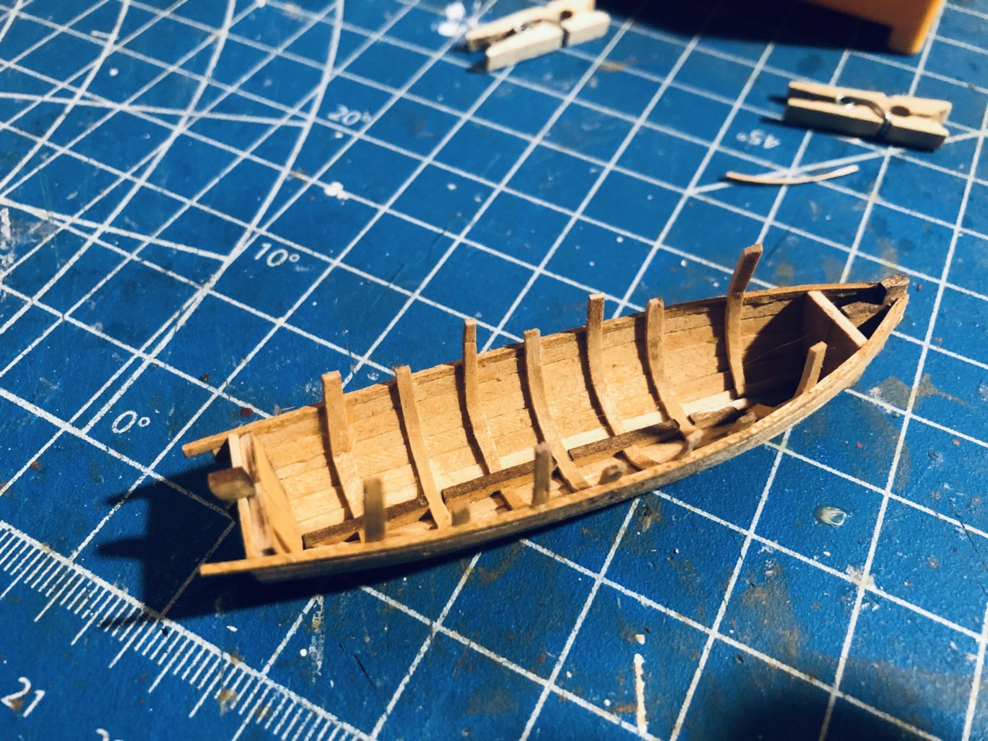
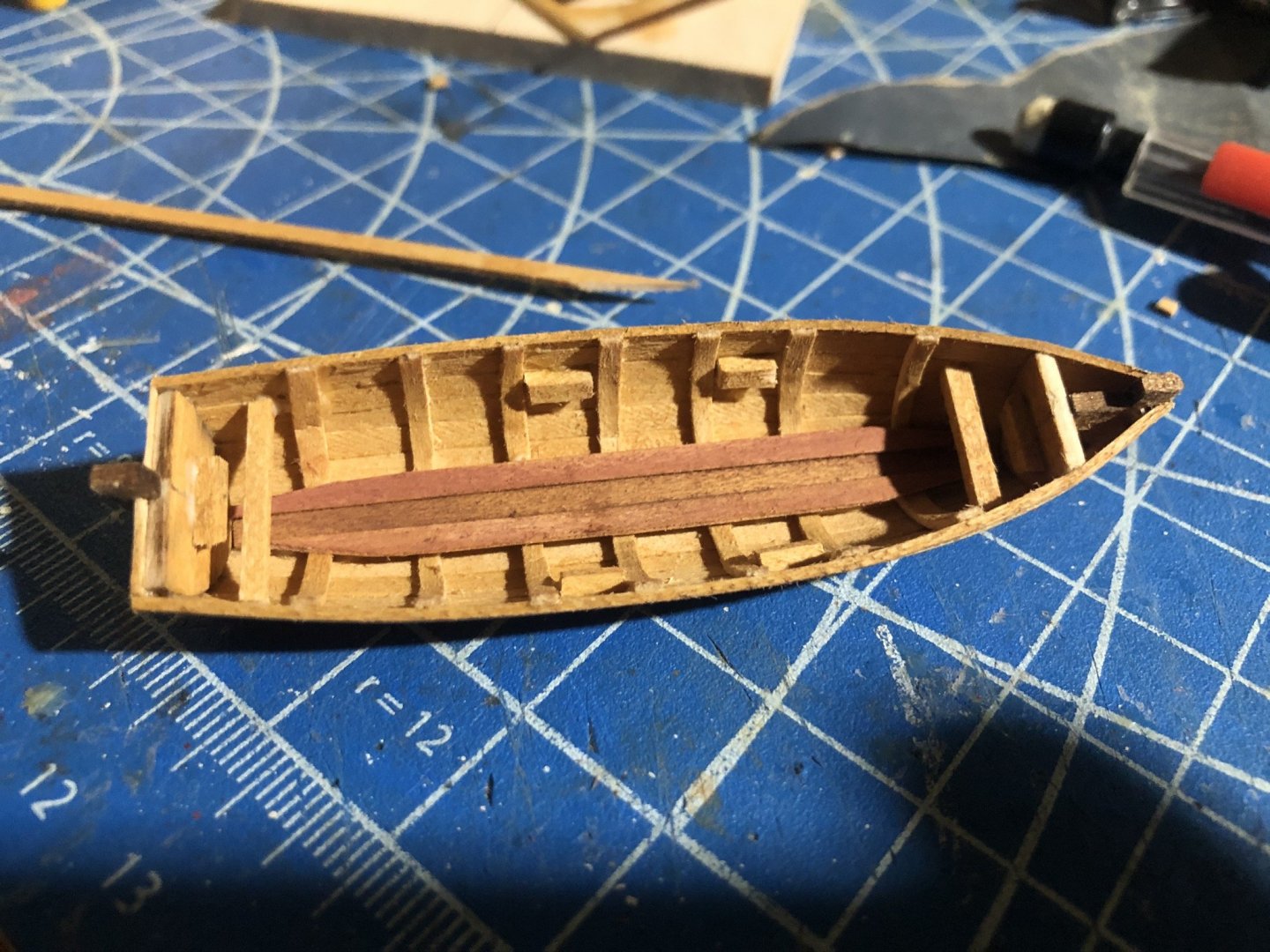
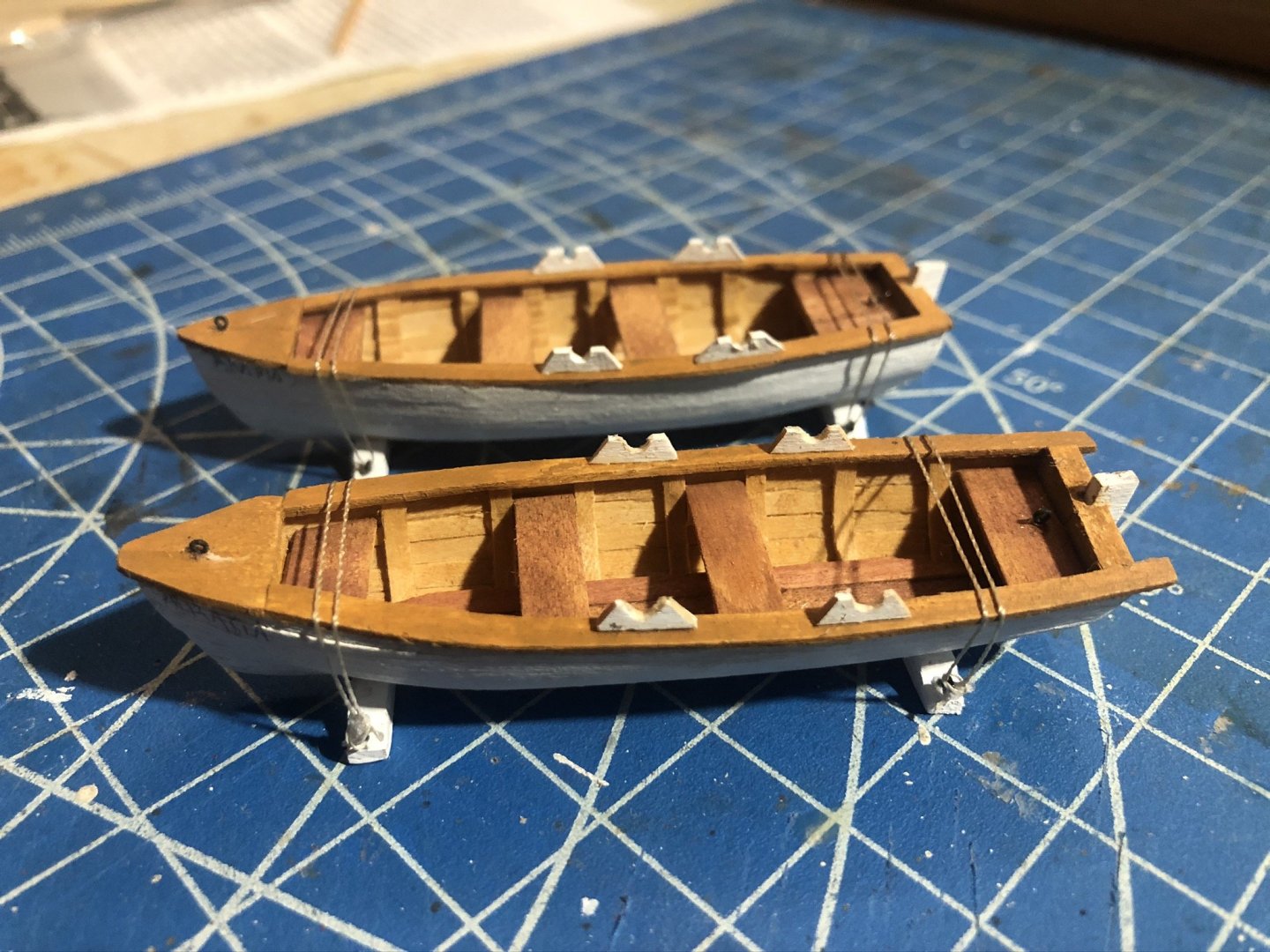
The second boat is done, I think it came out equally nicely. The kits provide so much extra wood that I was able to complete both boats using materials only from the first kit, except the actual laser-cut keels and formers. Here's a quick slideshow of the second boat's development. Next I'll post a list of suggestions for tackling these kits (improving on the very poor instructions). Laying the first planks. I left out rib former #1 (nearest the bow) as this is really wide and creates a sharp, bluff bow that's difficult to plank. I wanted a sharper bow anyway. For the ribs, I didn't even try using the 1/16" square stock as it's way too thick for easy use or accurate appearance. Instead, I used the much thinner planking stock and cut its width down to something more realistic. Looks much better and didn't crimp nearly as badly as in boat #1. Someone suggested laminating several strips, but I didn't need to, one held up just fine. Planking continued, showing my clamping methods. I didn't soak any of the planks for this boat, as I found it wasn't necessary with the improved bow shape. Instead, I shaped each plank to fit, then marked its exact location on the central three ribs. I glued each one to those ribs, then once that was dry glued the bow and stern portions with their bends. The original gluing held the plank in place and the strips are thin enough to accept even the near-90° bends I gave them, with slow application. Here you can see the bow portion sticking out, waiting to be glued and clamped once the rest is dry. This worked great and saved a ton of time. I didn't try to finish planking the hull while attached the build board as there's no place to apply clamps once the planking gets close to the board. Rather, I cut the boat off early and finished the planking on the loose model. Below is the boat cut loose without its last strake. I think you could cut it off with the last two strakes missing and be fine. This also shows the extra ribs fit into the open hull, which I made by cutting planking strips into narrower pieces that look better. Fully planked hull with floor added and braces for the seats. Three views of the finished boats. They look pretty similar, but #2 took half the time as #1 due to some of my changed methods, and I think looks better with thinner and less deformed ribs: Next post will share a detailed set of suggestions for working on this.


- 29 replies
-
- 8
-
-
- ships lifeboat
- model shipways
- (and 1 more)