


Cathead
-
Posts
3,524 -
Joined
-
Last visited
Content Type
Profiles
Forums
Gallery
Events
Everything posted by Cathead
-
 Wefalck, you've got us thinking about a trip down to the river to collect some authentic sediment and laying it out in a wooden tray, fixed in place with diluted glue. Could even embed a snag or two made of twigs. Mrs. Cathead used to do research modelling changes in the Missouri River's channel and would have a lot of (too much?) fun recreating typical river-bottom morphologies. She even suggested using a 3D printer to create an actual river-bottom model based on existing scan data, though I think that's beyond us.
- 599 replies
-
- 4
-

-
- sidewheeler
- arabia
- (and 4 more)
-
So I have a new question for you all. I've decided I need to build the permanent stand next and mount the Arabia on it, as doing so will require tilting the model back and forth rather dramatically and I don't want to do that with delicate loose rigging. Last night I tried a stand design that looked good in my head but I'm not a fan of in reality. I thought it would mimic the lid of a cargo crate and tie into the model nicely, but instead it just looks clunky to me: So the question is, what sort of stand design would look good? I left mounting holes in the bottom of the hull that correspond to the second and fourth crosspiece on the stand above. They are in two pairs about 4" apart laterally. So I need to design something that will look good, be attachable to the hull while it's stood on end, and be stable enough for this wide model. Thoughts?
- 599 replies
-
- 3
-
-
- sidewheeler
- arabia
- (and 4 more)
-
If there's one rule about Western River steamboats, it's probably "never say something didn't happen". I also found a drawing in an old Time Life book of the Far West that shows her grasshopper spars being hooked onto the rigging from the poles (rather than actually rigged together), implying easy potential for removal if necessary. That's a detail I haven't seen anywhere else due to photo resolution, etc. I think I'm going to copy that for Arabia as it's a nice touch and also makes the rigging a little easier!
- 599 replies
-
- 5
-
-
- sidewheeler
- arabia
- (and 4 more)
-
Roger, I assume you're referring to this post? I can see the spars on the main vessel but the others seem cut off. Is there a wider version of the photo? Certainly good evidence that the practice was used wherever necessary. As for the lock/dam building, thanks for looking that up. Very interesting and quite different from the situation on the Missouri, where the first dam wasn't completed until 1940 (primarily for flood control) and serious channel modifications commenced from there. However, prior to that, there was an ongoing effort to improve the channel by pulling snags and so on; do you know how early efforts like that happened on the Ohio? I would assume that things like dredging and channel modification started well before actual lock/dam construction, which would reduce the problems with bars to a certain extent. Just theorizing, though. I can easily believe that all upper tributaries along the Ohio remained shallow-water rivers requiring some use of sparring until navigation was either improved or abandoned (which I'd bet happened earlier than along the Missouri given the relative pace of development for competing things like railroads). So much to know, so little time.
- 599 replies
-
- 4
-
-
- sidewheeler
- arabia
- (and 4 more)
-
New Member: Boats Billy, Wichita, KS
Cathead replied to Boats Billy's topic in New member Introductions
Welcome from the other side of the border! That's a cool project you're taking on. -
Funny you say that, as I was studying photos and such yesterday I was looking at that as well and wondering what it was for, given that it seems to serve no functional purpose controlling the pole itself. All the accounts of grasshoppering I've read mention of only the bar-hopping purpose of the setup, but that omissions doesn't mean the poles weren't also used for something else. One question I can't answer, though, is what happened to the actual spars if you did that. They seem rather large, heavy, and awkward to leave hanging from the pole while you were swinging cargo or some kind of landing platform around, yet taking them off would be a major task. I've always seem them presented as left rigged and ready (hanging at the sides of the bow for immediate use), so it would seem really awkward to derig them every time you made a landing somewhere. See the St. Louis photo, where all the spars are hanging in place. Note that in the second Mary McDonald photo, she has a stage/platform out to the bank on the port side but the grasshopper poles are still rigged, and there's no sign of the port pole being rigged to the platform or otherwise in action (it's in the same position as the starboard one). I'm also not convinced that I can see the secondary rigging on the poles that's so clear on the Far West, just the main rigging for the spars. The real answer is I just don't know. Anyone else have info or perspective? There's so much to know, and there are so few details as most contemporary people took stuff like this for granted, weren't interested in documenting it, or weren't capable of doing so. I'd love to have another life as a historian to just dig up and read every contemporary account of steamboat travel to try and find nuggets like this, but they're really hard to search for from an amateur setting.
- 599 replies
-
- 5
-
-
- sidewheeler
- arabia
- (and 4 more)
-
Rereading Alan Bates' Steamboat Cyclopedium in preparation for setting up the grasshopper spars, I noticed a detail that may explain some of the uncertainty about the use of spars on the Missouri vs. other rivers like the upper Ohio. Bates gives a drawing of "the manner of using a spar to lift a steamboat off a shallow place". He assumes that the steamboat has a central derrick (like that used for stages or cargo, as on Chaperon) that is used to drop a loose spar in place along the side of the bow. This is then rigged to the capstan, which hauls on the spar uses it to lift the boat over the bar. He shows a very short spar that would presumably only be set up when needed. This couldn't have been a permanent setup as the derrick had other uses, so must only have been done occasionally. This is very different from what I think of as the Missouri River design, in which boats have two permanently rigged spars (one on each side), with their own dedicated infrastucture, that are ready to use at a moment's notice and often. Here are proper grasshopper spars on the Far West (image from a model in the Smithsonian). Note the dedicated boom and permanent rigging for each spar, but no central derrick for cargo or a stage: This doesn't mean such a system couldn't have been used on the Ohio or other rivers, but I've always seen this described as a Missouri River feature. It makes sense to me that when bars were not a permanent and constant feature of the system, boats might have used Bates' temporary system instead. In other words, "sparring" over bars happened anywhere shallow water occurred, but a permanent infrastucture dedicated to routinely hauling boats over bars may have been relatively specific to the Missouri (and possibly similar rivers like the Red and Arkansas). Just a theory, as I can't seem to confirm this, but it makes sense to me. I'm not sure when the proper "grasshopper" system was first developed, but this image dated to 1853 clearly shows grasshopper-equipped steamers at the St. Louis landing (image from the Missouri History Museum): Thus it's easy to assume Arabia (built in 1853) had grasshopper spars by 1856, especially once she was transferred to Missouri River service. Here are two more views of the typical system from the Mary McDonald, one of my references for this build (from the University of Wisconsin collection), which was built in St. Louis in 1866 for the Missouri River trade.
- 599 replies
-
- 10
-
-
- sidewheeler
- arabia
- (and 4 more)
-
What a fun project, thanks for sharing with us!
- 38 replies
-
- 1
-
-
- finished
- marine model company
- (and 1 more)
-
Wow, water levels in the Ohio got awfully low! I'm going to miss this build so much. Your detail and metal skills are better than mine and you've done such a nice job making a crisp, unique, and attractive model. It's been nice to have this as an inspiration and nudge to keep progressing on my project. I think someday I'd like to get this and kitbash it into a backdated Civil War era Missouri River craft. In any case, congratulations on finishing. I sure hope you do post photos whenever you get a case set up. Thanks for sharing this journey with us.
- 133 replies
-
- 2
-
-
- chaperon
- model shipways
- (and 2 more)
-
It certainly makes sense that low-water conditions would occur in various places, especially by late summer. Given that, it's still the case that the Missouri River was unique from the others in being especially shallow and sediment-dominated with multiple narrow channels braiding together (rather than one main channel defined primarily by bedrock, as in the Ohio basin), and especially prone to low-flow conditions given its arid drainage basin. There's a noticeable shift in annual rainfall across roughly the Mississippi River. For example, at a chestnut-growing conference I attended a few years ago, it became very clear that growers east of that line (Ohio, Michigan, Indiana) saw no need to use irrigation in their orchards and everyone west of that line (Kansas, Missouri) was shocked that they didn't. It's also worth noting that Arabia was built before the true "Missouri River" style of steamboat was developed. By the 1870s, when the Ohio and Mississippi were well on their way to being tamed, the Missouri (especially the upper river) was still in its native form and very hard to navigate. So a style of boat developed with a "spoon" bow that was especially good at sliding over sandbars and pulling up onto (and off of) banks, a low superstructure to deal with high winds, and little to no guards extending beyond the hull to make narrow channel navigation easier. Arabia is basically an Ohio River boat taken into a very different and much rougher river. Look at something like the Far West to see what a proper Missouri River boat looked like. As with any such discussion, we're trying to simplify really complex natural and human systems into a few paragraphs. A whole book could be written about the geologic and geomorphic differences between the very diverse basins in the Mississippi system and how that influenced steamboat navigation and design; most steamboat books I've read only touch on the scientific backdrop to all this.
- 599 replies
-
- 6
-
-
- sidewheeler
- arabia
- (and 4 more)
-
There's a short video on the Arabia museum's site that I hadn't seen before, introducing their search for the Malta (a Missouri River boat that sank way back in 1841). It's interesting in its own right, but it also has a number of still paintings and photographs showing how "gangplanks" were used on the shallow Missouri rather than stages to access the shoreline, with boats just run up against the sand. I also did a bit of reading and found multiple references to sparring being used on the upper Ohio as well. Makes sense, once the water gets shallow enough, that sediment bars would form there too and force a similar need. But I still think it's accurate to say that grasshopper spars were a really diagnostic feature of Missouri River boats.
- 599 replies
-
- 5
-
-
- sidewheeler
- arabia
- (and 4 more)
-
Civil War ironclad by philo426
Cathead replied to Lucius Molchany's topic in - Build logs for subjects built 1851 - 1900
This looks interesting. Can you tell us more about your methods and build activity? -
Brian, great and insightful question(s). It's going to take an essay to answer them, which I want to get right, so I'll get back to you. Really short answer is that the Missouri had a unique combination of shallow water, variable flow, and a sediment-based channel that meant steamboats couldn't avoid or go around sandbars but had to go right over them, unlike the Ohio or Mississippi Rivers for reasons I want to take the time to explain properly but relate to the unique geology and climate of the Great Plains. I believe such spars would have been necessary on other rivers draining the arid West, like the Arkansas or the Red, but am not 100% certain whether they were used. As for the landing stages, because the Missouri was shallow and sediment-based, boats usually just ran themselves up onto the shoreline and unloaded from a plank ramp set down (think a gangplank on sailing ships) because you couldn't get close enough to dry land to use a stage effectively. Stages were used in the more eastern bedrock rivers where you didn't want to run up onto the shore, or on the lower Mississippi where the water was deep enough that you could just pull up to a bank and offload by a stage. It was also more civilized down there, unlike the much rougher Missouri basin, where a plank would do nicely. Grasshopper spars could not be used as loading booms under normal circumstances, their sole purpose was to drag the boat bodily over a channel-spanning sandbar, often many times a day. Another factor in loading booms was the kind of freight being carried. Big bales of cotton or other ag products might need a loading boom of some kind, but those crops were restricted to the middle-lower Mississippi and portions of the lower Missouri. Normal everyday cargo like barrels, crates, lumber, etc. were moved by sheer muscle power (sometimes slave, pre-ACW). Arabia was originally built as an Ohio River boat, so may have had a stage at first, but if so that would have been removed once she was shifted by a new owner to Missouri River service and grasshopper spars would have been installed at that time instead. Chaperon didn't have grasshopper spars (a) because she remained in the Ohio basin and (b) because she came along late enough that channel modifications were already happening (like dredging) that ensured boats could navigate freely. Back in 1856, you were entirely at the mercy of the channel, especially far up the Missouri where the water was often only a few feet deep and snags were everywhere. Boats like Arabia quite literally slithered over channel-spanning bars like an otter, their hulls capable of flexing rather dramatically for those used to sailing vessels (one reason for all those hog chains was to allow for a flexible hull; a maritime hull would break its back in no time on the Missouri). This is all simplified and was really more complex. For example, the lower Missouri takes on many characteristics of the middle-lower Mississippi (I don't doubt that boats with stages worked the lower Missouri). Finally, Arabia is particularly unusual because few sidewheelers went up the Missouri beyond roughly modern-day Omaha, because they struggled with the shallow, snag-filled conditions of the upper Missouri. Sternwheelers were far better suited to these conditions. It's amazing to me that Arabia went all the way to Montana, even partway up the Yellowstone, as a sidewheeler. Okay, that wasn't short at all, but there's so much more to say. Hope Kurt, Roger, or anyone else will correct me if I said something mistaken in my enthusiasm. Will try to write a more cogent explanation later. As for fully rigged ships, the closest I've come was my revenue cutter (see link in signature), which was quite interesting. Maybe someday, but I have limited display space and sailing vessels just have so little relevance in the Ozarks. Believe me, I'd love to. I grew up near Lake Ontario and sailed quite a bit as a youngster, but ended up here as an adult so have adopted the maritime tradition of my new home. I do have a someday dream of scratchbuilding the brig Ontario, which sank in Lake Ontario and has had a very nice book (with full drawings) written about it.
- 599 replies
-
- 5
-
-
- sidewheeler
- arabia
- (and 4 more)
-
2020 NRG Conference
Cathead replied to kurtvd19's topic in NAUTICAL RESEARCH GUILD - News & Information
Huh, I don't think I got that email. This was the first I knew of, though I was expecting something of the kind. We were strongly considering going, so hopefully it'll work for us in another year. Definitely the right decision under the circumstances. Thanks for getting the word out, Kurt. -
Forgot to say, I totally agree. Granted, I've never rigged a big three-master, but I really like the visual appeal and logical puzzle of rigging. I certainly think the extras I added to Arabia add visual interest to the otherwise somewhat spare topside, and grasshopper spars are great for adding complicated eye candy!
- 599 replies
-
- 5
-
-
- sidewheeler
- arabia
- (and 4 more)
-
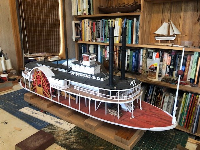
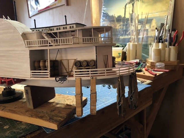
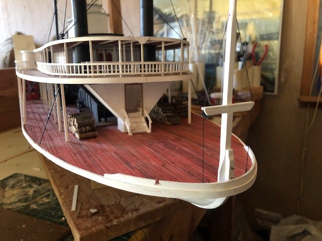
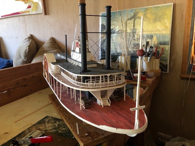
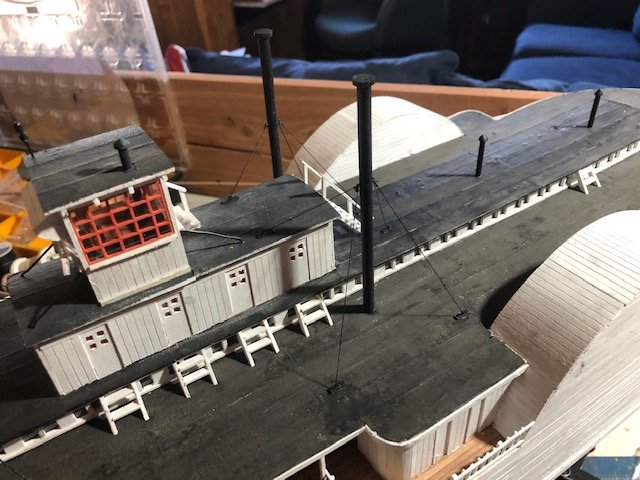
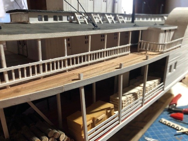
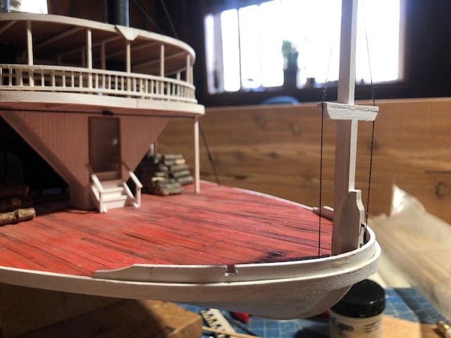
As is often the case, what I thought I'd do next wasn't what I ended up doing next. Instead of the capstan and grasshopper spars, I focused on other details. For example, I added strips of wood sealing in the edge of the main deck. For the curves around the bow and stern, these were soaked, bent, and dried, then painted while held in a jig so the paint's moisture wouldn't undo the bend. Worked pretty well. It's hard to tell the difference in photos, but they really clean up the deck's edges in person. I added other bow details, such as the jackstaff and the curved bit of wood extending above the deck around the bow (no idea what this is called). The latter was tricky and took several tries. I consulted various photos and drawings of different jackstaffs, then went within a design I liked. This would have been attached to an extention of the stem (coming out through the deck). Some were strapped on with iron; I chose to "bolt" mine on instead. The jackstaff was not a flagpole but a navigation aid. The pilot could use this to as a reference point when sighting against faraway landmarks like ridges, bluffs, trees, and islands. The relative motion of the boat and jackstaff helped him judge the boat's actual movement in difficult navigational conditions. The red ball, called a "nighthawk", was placed roughly at the pilot's eye level as an additional reference point. Based on photos, some boats had rigging bracing the jackstaff and some did not. I added a bit, both for visual interest and for reasons explained after the next photo. I also added support lines to the engine steam vents. As far as I can tell, like the jackstaff rigging, some boats did this and some didn't. I decided that Arabia, which navigated far up the Missouri River into the windy Great Plains (deep into Montana), would want the extra bracing in both cases. For similar reasons, I added "iron" bars bracing the vulnerable pilothouse. Finally, I rectified an early mistake. The lower posts supporting the boiler deck should extend through the deck just a little. I didn't do that early on, so cut a series of short "post" stubs and glued them on top. Looks pretty convincing. Pretty soon I'm going to need to build the final stand, as I'll want to attach her permanently to that before doing the most delicate work (like the grasshopper spars). I have a lot of well-cured cherry lumber in my barn that I cut here years ago, and think I'll try to put something together with that. I ordered a few last details from Model Expo (like a bell and two boat kits), so whenever those arrive they'll help add some more details. That order also included my next project, which I'm already looking forward to. Having it in hand will encourage me to finish this model. Thanks for reading. The end is now in sight, though it's weeks away yet.
- 599 replies
-
- 15
-
-
- sidewheeler
- arabia
- (and 4 more)
-
Just a thought, but as long as you're considering nail holes, keep in mind that planks were nailed to every deck beam, not just the ones at the end. In practice, you'd have parallel sets of nail holes every scale foot or two along each plank. Of course, that's a lot of work and you could decide it would make the deck look too busy, but I thought I'd suggest it. Your approach highlights the idea of nailed planks while leaving a clean-looking deck that emphasizes the planking. Especially given that this kit isn't particularly prototypical, the best choice is whater you think looks best!
-
One trick I've found very helpful personally, choose a "good" side for the model (the primary display side) and always do uncertain tasks on the other side first. For example, if you plan to display the port side, plank the starboard side first so any initial mistakes are less visible at the end. Same for anything else that has a "side".
- 950 replies
-
- 5
-
-
- syren
- model shipways
- (and 1 more)
-
Prices can reflect a lot of things. For example, how old is the kit? If it's been around 20 years and the manufacturer has long since paid off the development costs, it might be sold cheaper as they can just churn out replacements. If it's newer, it may be more expensive because it takes a lot just to develop a kit, but it also may be a better kit as manufacturing methods and other aspects of improved over time. Quality of materials is a big one, and may relate to kit age. Newer kits are likely to have better-quality materials, which you might have to pay for but are well worth it. Then there's the question of who's doing the selling; different outlets have different business models; the cheapest price might not be fair or sustainable depending on the background context.
-
Do you work at a hospital or were you a patient? Regardless, glad to see you're still working on this.
-
Nice touch adding working hinges!
-
As you asked, I have built one Corel kit and swore never to again as I found the instructions, materials, and kit design rather poor and frustrating. However, there is no doubt that even a bad kit can be completeted successfully and attractively with enough perseverence, patience, and research into the necessary skills to overcome its flaws. So keep at it if you really like this particular prototype. As others have said, starting a proper build log is likely the best way to get ongoing help with your build.