HOLIDAY DONATION DRIVE - SUPPORT MSW - DO YOUR PART TO KEEP THIS GREAT FORUM GOING! (Only 69 donations so far out of 49,000 members - Can we at least get 100? C'mon guys!)
×


glennreader
-
Posts
136 -
Joined
-
Last visited
Content Type
Profiles
Forums
Gallery
Events
Everything posted by glennreader
-
 Ah. This is now called the 'Rudder spigot'. Your model probably did not include these instructions that can be freely downloaded from the AL website. Go to https://www.artesanialatina.net/en/classic-collection/429-scottish-maid-classic-collection.html Select the instructions tab and then download '18021 Color'. Panel 12 may be of help. It shows how to make the rudder and fit the 'helm axel' or 'Rudder spigot' and where that hole should be. I agree, drilling that hole does not look easy. My plan is to position a vertical post on the drill stand and align the drill so it is on top of the post. If I then hold the stern post of the model against this post with the deck upmost and drill down through the deck etc, then the drill should come out just behind the stern post, where it should. Does that make sense? Glenn
- 87 replies
-
- 1
-

-
- scottish maid
- artesania latina
- (and 1 more)
-
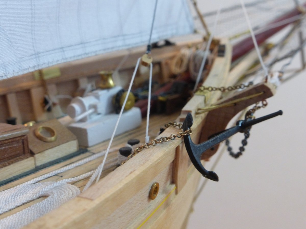
No such part on my newer kit. Maybe it is what is now labelled as 'Rudder wheel shaft'. A short length of 0.8mm brass rod that is part of the steering gear, forming the axel for the wheel and a drum for the rudder tiller rope. Glad you managed to take a sharper picture, the colours of the woods are looking good. For anyone thinking of getting this kit, it now includes pre-cut pieces for the forward sections of the capping rail, eliminating the need for a sideways bend. The rest can easily be done with straight strip. Glenn
-
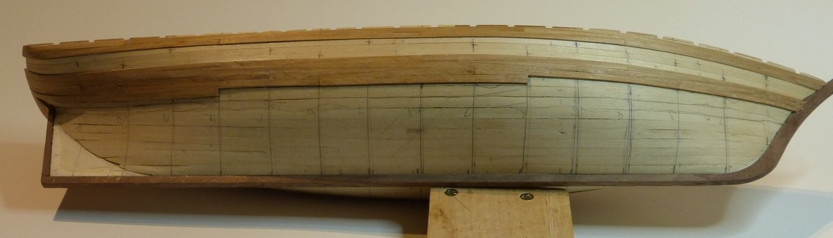
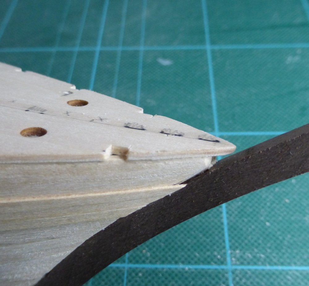
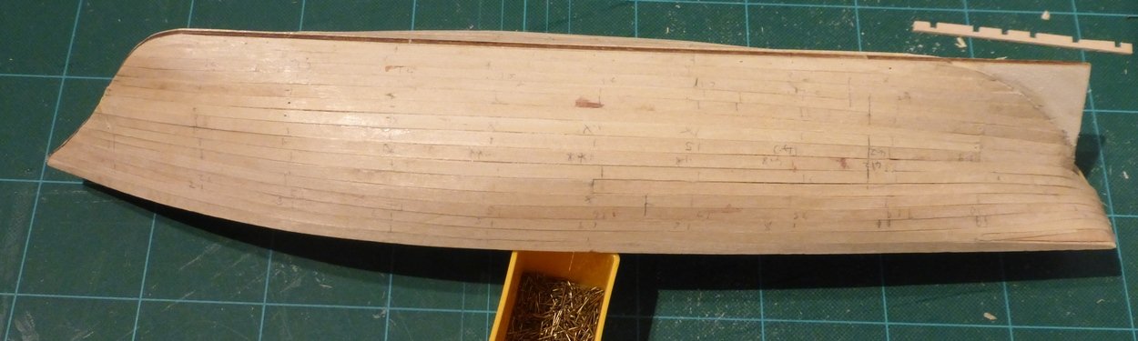
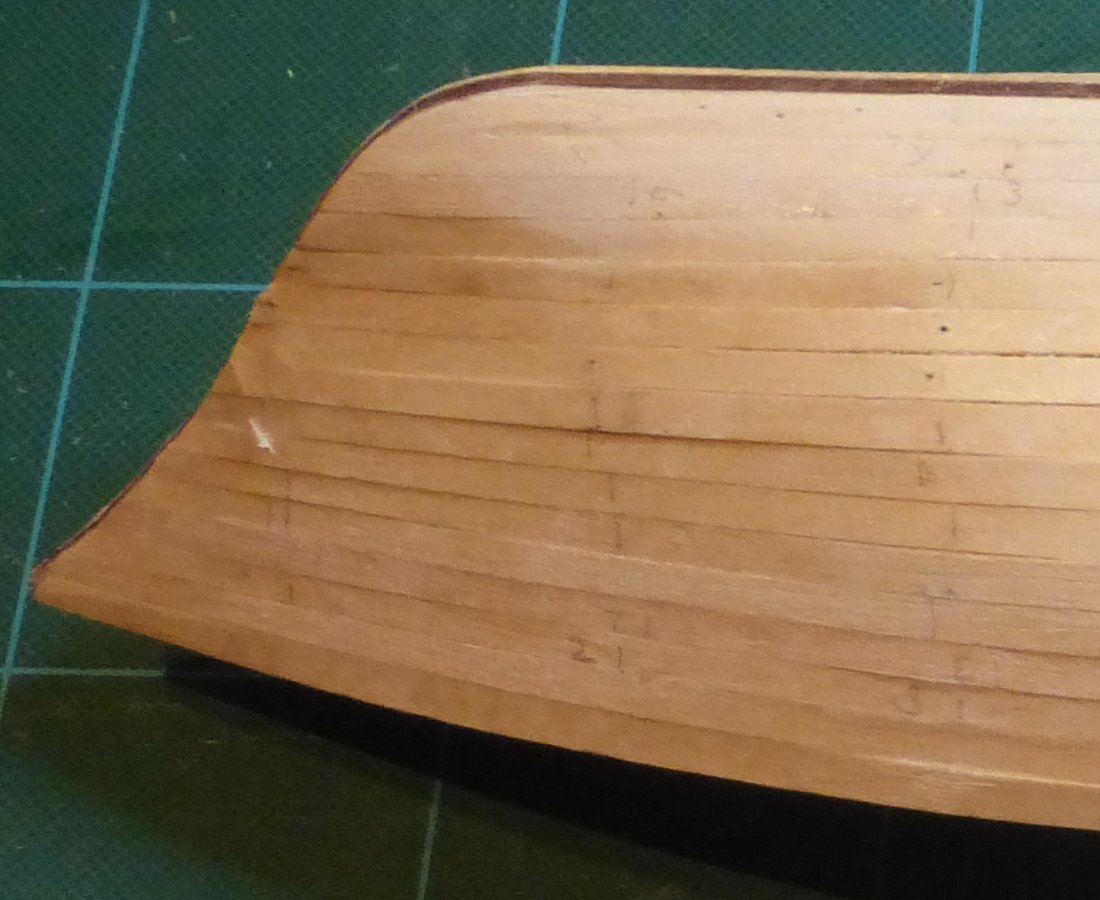
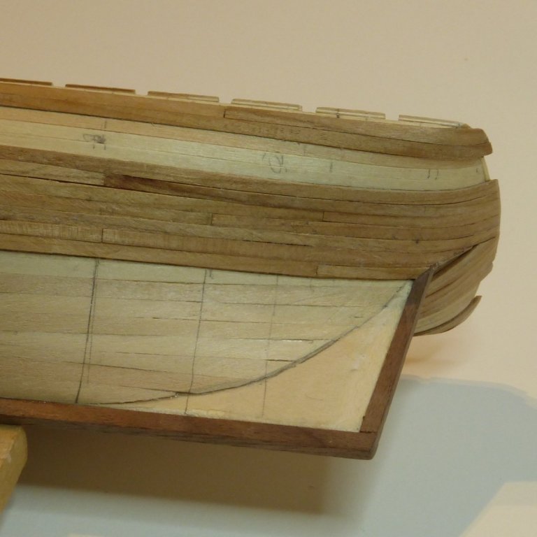
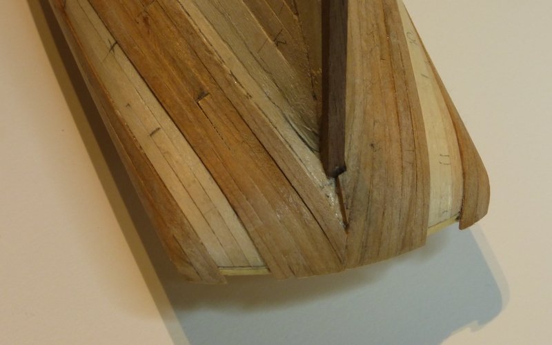
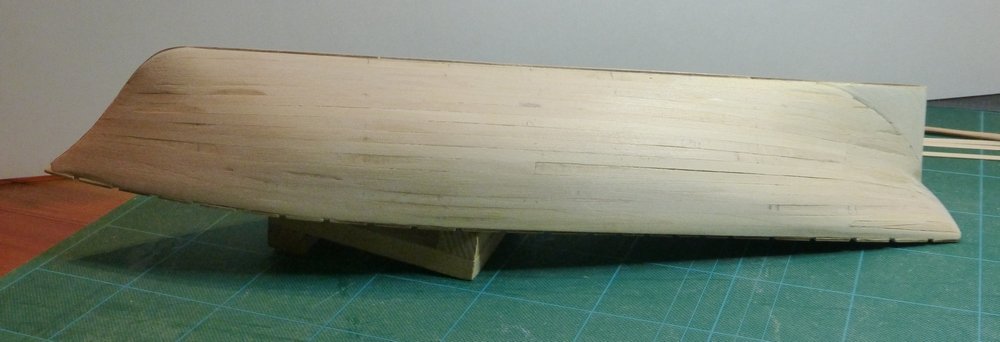
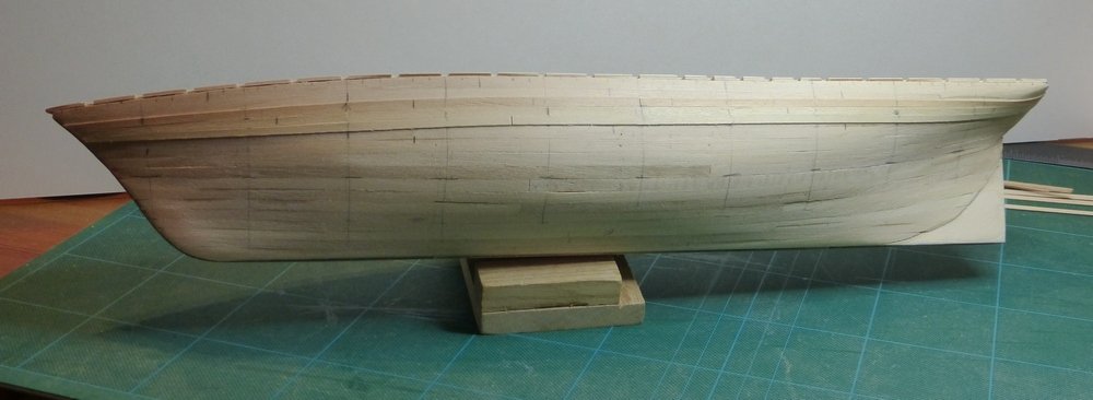
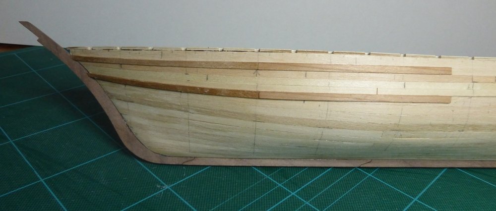
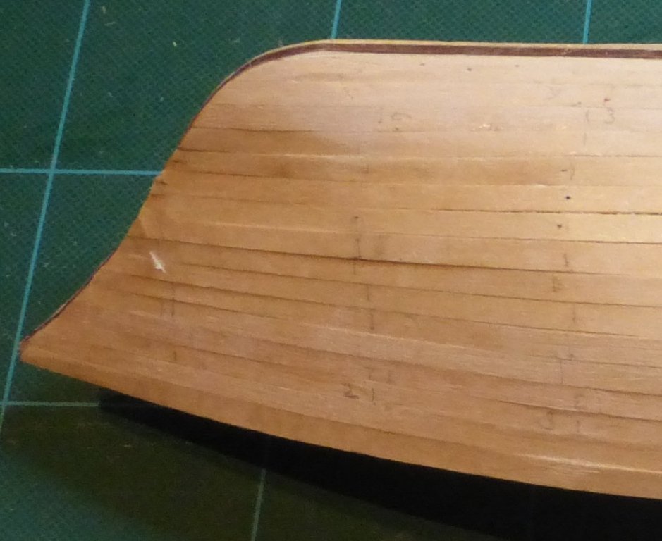
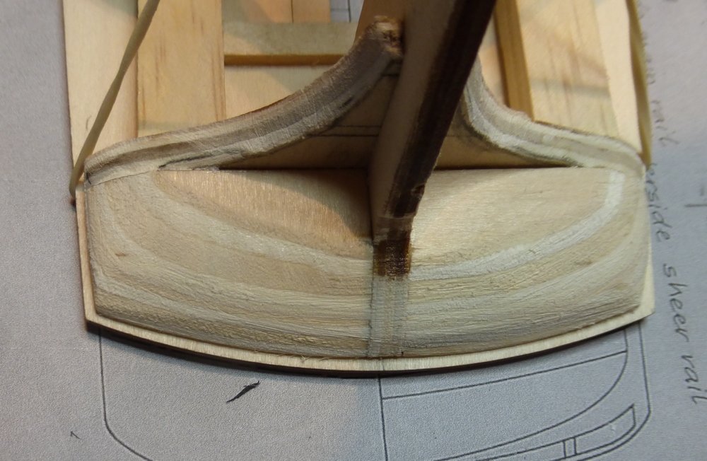
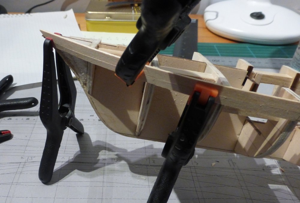
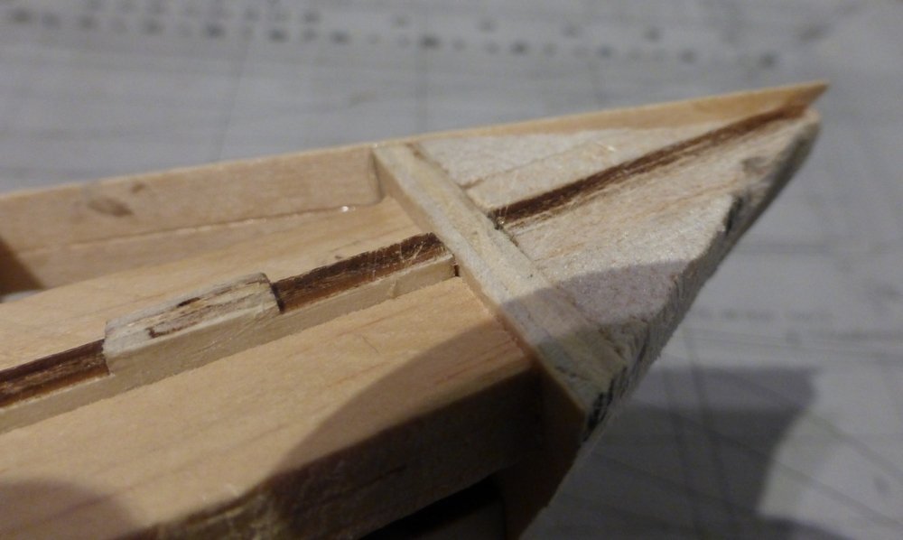
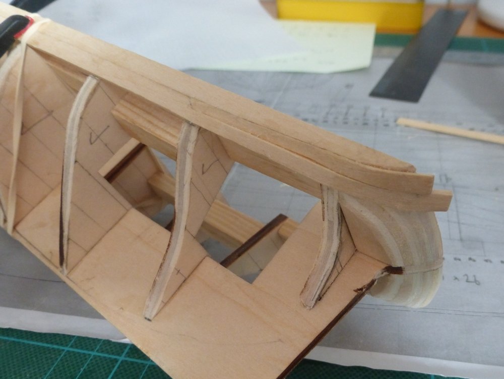
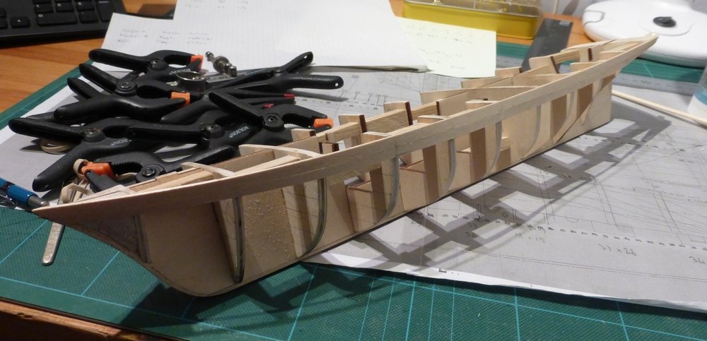
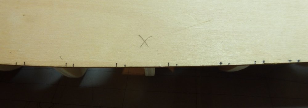
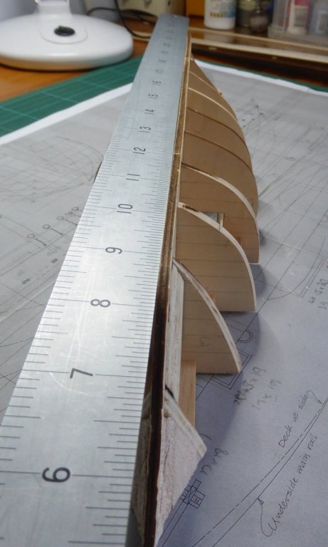
I know its been a long wait, but thanks to every one that looks in and as always thanks to popeye for the encouragement. Progress was very slow for a few weeks. I have been marking maths papers and there was a death in the family. Getting done everything that is required when someone dies is very time consuming. Not finished, but the bulk of it is now behind me. I have been progressing with the second planking and the rate should pick up a bit now. On the first side I have completed 2 strakes above the wale and 7 strakes below, to the point where the next strake will abut with the stern post and not run up the counter. Also a couple of closer shots Those of you who are paying attention may at this point notice something wrong with the bow. If not here is another picture to help. There was an accident. I am one of those people who plank in their lap. The model was on an old towel on my lap and I reached for the glue. As I did so the model gracefully launched itself pointy end first onto the wooden floor. It was a bit surreal. I just sat and watched it go, as if it was in slow motion. I am certain I could have just reached out and stopped it. Still it is a very clean break and when held in place the break cannot be seen, so at the appropriate point, when it is needed I can glue it back on. As for the other side, I have not got quite as far. I will catch up with the first side before going further with either side. The lines mark where every 4th frame would be on the original. On the model this is where planks start and finish. I had a lot of trouble drawing these lines. I think I must invest in a laser level. This is the first time I have attempted planking like this on the hull, instead of using a continuous plank for each strake. The most important thing that I have learnt, very quickly, is that every plank is a different length. These differences are only small, up to about 4mm, obviously caused by the curve of the hull. But they necessitate that each plank is laid in place on the hull to be measured and cut to length. I am very much enjoying this approach and would recommend it. I am finding it easier than continuous planks and cannot see myself going back to that method. Like with all things there is a learning curve and there are some small gaps in places, but I am sure I can cover these up so they are not too noticeable. Also hopefully there will be no more. A close up of the stern. I was pleased with the way the wood I am using bent over this section. After a couple of hours soaking it took to the shape very easily. There is a small gap between the rear of the stern post and the plank. This will not be a problem as it is required to remove material there to make a hole for the rudder trunk. Not sure if I will just make a round hole for this or try and make it with a section like a quarter circle, which, I think, would be more accurate and more interesting to attempt. Once I reach the keel I will sand all the planking before doing the wales and the 3rd plank above the wales which is also slightly thicker. I am using this drawing as a planking guide. This is the original, that I scanned in. I printed this out then used the frame that the bulkheads came in to draw the outline of the largest bulkhead in the middle. I then took a guess at the 'centre' and drew lines radiating from this to the edge of the wales to determine their position. I cannot fit quite so many strakes in, so above the wale there are 2 normal strakes then the 3rd strake will be the same thickness as the wale. Above this will be a rail and then the bulwark planking. Though I shall do the cover plank and the deck planking before I do the bulwark stanchions and planking. That's all I can think of to say about hull planking. Actually, I am surprised I got that much. Glenn


-
I think caulking is a bit suck it and see. I do not think that colouring the edge looks very even, especially if the wood is not good quality. Then again gluing paper to the edges is very difficult with very thin planks, not really practical with anything less than 1mm. On my last model, with 0.6mm planks, I tried gluing cotton between the planks as I laid them. I think this was reasonable, but not easy to do the ends. Also you have to be very careful not to sand the thread when sanding the deck, otherwise it frays and looks terrible. When I get to it on my Scottish Maid, I am going to replace the supplied wood with some 1mm planks I have and try sticking black paper to the edges. I have not tried this method before. Though I am a bit worried about how to scale it will look - use thin paper. I would suggest that if you have any spare wood you try it out somewhere off the model. You could then compare the different methods and see what you like. If you have not seen it, try reading this article: http://modelshipworldforum.com/resources/Framing_and_Planking/Deck_PlankingIIbuttshifts.pdf. Glenn
- 87 replies
-
- 1
-
-
- scottish maid
- artesania latina
- (and 1 more)
-
Looking good, you have overtaken me. I have had very little time in the last few weeks. Cannot tell from the pictures, but are there holes in the deck or have you marked the positions for where the masts go? I think I see various items of deck furniture on your lamp stand. Glenn
- 87 replies
-
- 2
-
-
- scottish maid
- artesania latina
- (and 1 more)
-
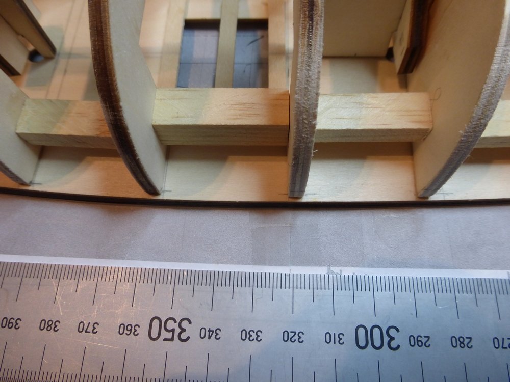
Popeye, Nice to have you along. Making slow progress, life getting in the way. Working on the hull planking, but I have now started the second planking. After finishing the first planking the hull was given a light sanding. There are still a few small cracks and depressions, but nothing the second planking will not cover. They probably look worse in the picture due to shadows from the lighting. I intend doing the second planking with 1mm thick planks. This is close to the scale thickness of the real planks which were 2.5in or 0.992mm at 1/64 scale. This will make the hull the correct size as the first planking coincides with the frames. For the wales the real planks were 3.5in which corresponds to about 1.4mm at this scale. To get this thickness I have first placed 0.5mm planks where the wales go and will later overlay these with the 1mm planks. I do not think the extra 0.1mm will be noticed. I was not sure at this stage if I could do the second planking before attaching the keel, sternpost and stem. After holding these up to the model and looking at how the planks would fit, I have decided that it would be almost impossible to do the planking first and get a good looking fit. The next question was do I cut a rebate or not. In the end I decided not to as I thought I could get a decent look without. So my next step was to glue on these pieces. I first cleaned up all the burning left from the laser cutting, where it was not wanted. I left it in the scarf joints on the keel and where I was gluing it to the hull. The first piece was the stern post which also required trimming to length. Then I started at the bow for the rest. As can be seen in the following picture, the last piece also needs trimming to length, which has been done since I took the picture. Those 0.5mm planks went on really easily forming a nice curve on the first planking These next two picture give an indication of how much the planks overlap at the bow. The first shows a plank as it would be just below the wale, the next is how far the wale will overlap. I have also glued the false deck in place. There are a couple of small gaps where I was a bit over zealous in sanding the top of the first planking. But nothing to worry about. The interesting bit is where the front of the false deck meets the bow. The false deck finishes in a nice pointy bit, while the bow is 4mm thick. I see trouble ahead … Finally I have cut and positioned the first 4 planks. Two in the strake above the wale and 2 in the strake below. As there are 3 strakes in the wale and I am using a 4 strake planking system, the ends of the planks in these two strakes end on the same frames. By my calculations, 4 planks done 256 to go (26 strakes a side, 5 planks/strake, 2 sides). I am going for planks that go across 16 frame centres. That is 16 x 16” = 21’ 4”. In this scale that is 4”. Of course they are slightly longer as they come round the bow, Up to about 1/8 inch. A will also use slightly longer planks where there would otherwise be too short a plank near the bow or sternpost. However, I am also a firm believer in the fact that all trees do not grow to the same height and no commercial ship builder in his right mind is going to cut off and throw away lengths of wood when the plank is too long, likewise anything slightly short is not going to be passed over. In reality, the only rules are something like: · Minimum of 4 frames between butts in adjacent strakes · Minimum of 3 frames between butts with a complete strake between · Minimum of 3 complete strakes between butts on the same frame. What I will do, so there is at least some overlaying pattern, is to shift 8, shift -4, shift 8, shift 4 and on a 16 frame length you are back to where you started, with some wiggle room for pairs of adjacent planks. If you cannot visualise it, draw it out. This is not my idea, but I cannot remember where it came from. Glenn

-
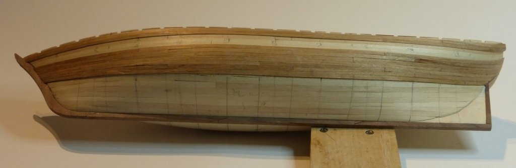
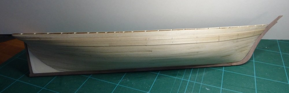
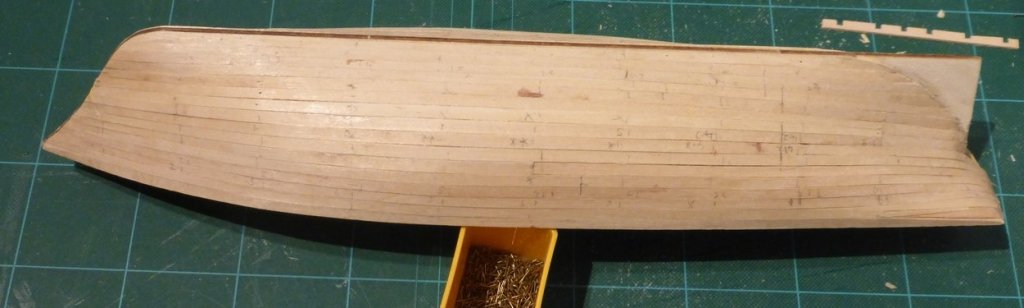
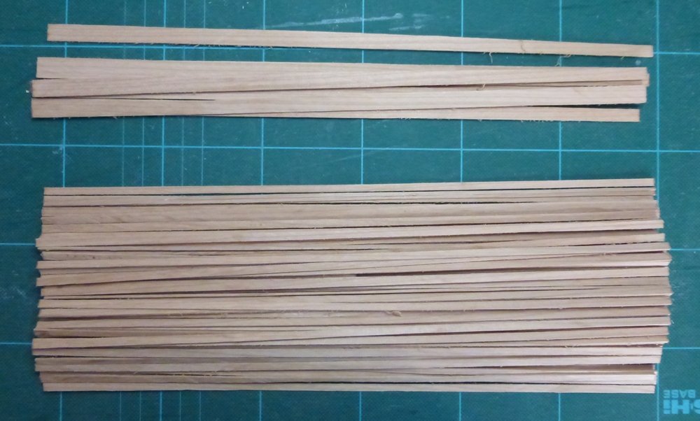
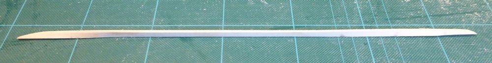
Popeye, good to see you along for the ride, hope you enjoy the build. Also thanks to everyone who just drops in. It is encouraging to see all the interest. I am getting close to finishing the first planking. There have been no real problems, in fact it worked better than expected. This picture shows a close up of the aft region with one plank left to fit. The plank to be fitted abuts the frame where I have gone down from 3 to 2 planks. I think this was probably easier than working with very narrow pieces. If you look closely you can also see where the 3rd strake from the keel includes a stealer. The only other stealer required was the one I used to get round that very sharp bend at the top. The other thing that worked out really well was where the run of the planks went from ending on the sternpost to running straight through on the stern counter. More luck than planning, but you take the breaks you get given. These two pictures show the two sides as they are now. I have finished one side, except for sanding and there are 6 planks to go on the other. It is not easy to see but there are some small gaps where the hull is at its widest at the turn from the bottom planking to the side. I always knew this was going to happen as in this area there was 31mm to plank with 5mm planking. So it was either let there be some gaps and try and spread them out or go from 6 strakes to 7, reducing the maximum width of each plank to about 4.5mm. Which seemed a lot of extra work for very little if any benefit. In the end this would also have affected the run of the planks from where they continue up the counter to ending on the stern post. I would have had to leave the top 2 planks at 5mm and reduce the remaining 5 to just over 4mm. Just thought I would also show a close up of the bow. In this area all the planks have had their width reduced by the same amount on each frame. There was a bit of lateral bending required, but not enough to warrant taking any special measures. I have also cut out where all the bulwark stanchions will be placed on the false deck. I did this with the help of the template shown. I made this on the milling machine, then realised it would have been much more durable made of metal rather than wood. However in the end it did not really matter. I have also glued some strips under the deck so I can block up the cut outs made for the hatches. For this I will use offcuts from the first planking, both are 1.5mm thick. I will then reposition the deck furniture so that it is in the positions shown on the McGregor plans. I will model the hatches battened down, so there is no need to model the interior as supplied in the kit. Finally I have been making sticks, lots of sticks over 120 sticks. Before I started this was a 12”x1.5”x1.5” block of pear. I bought this for 99 pence many years ago when a local shop closed. It was intended as a woodturning blank. I have a fair number of such pieces in various shapes and sizes, some intended for carving. But I would prefer it if the shop was still there instead. Not certain of the actual species of pear, I lost the label while cutting it up. Most of these sticks are now 3.5mm x 1mm x 12”. There are some wider ones just in case. This is what I intend using for the 2nd planking. 3.5mm is about the width required to represent a 9" plank. Still trying to work out exactly what plank length to go for. The frames are at 16” centres, which at this scale is ¼”. Therefore a 20’ plank would be 3 ¾” and stretch between 16 frames. The alternative is to go for something longer and get two full length and 1 shorter, which could be used at either the bow or stern. For instance I could get two 4 ½” planks and a 3” plank. Equivalent to 24’ and 16’ planks. Strake length varies from 13.5” to 17”. Just had a thought while typing. I need to draw out a planking chart or whatever they are called. Now I have thought of it I can’t wait to get started. Need to take some measurements and allow for the thickness of the planks. That's all for now, think I need A3 paper. Glenn
-
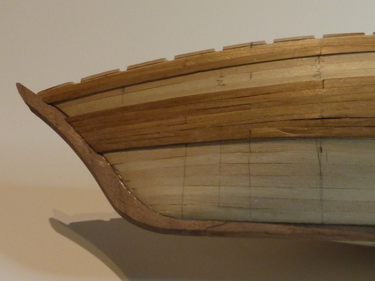
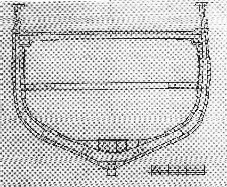
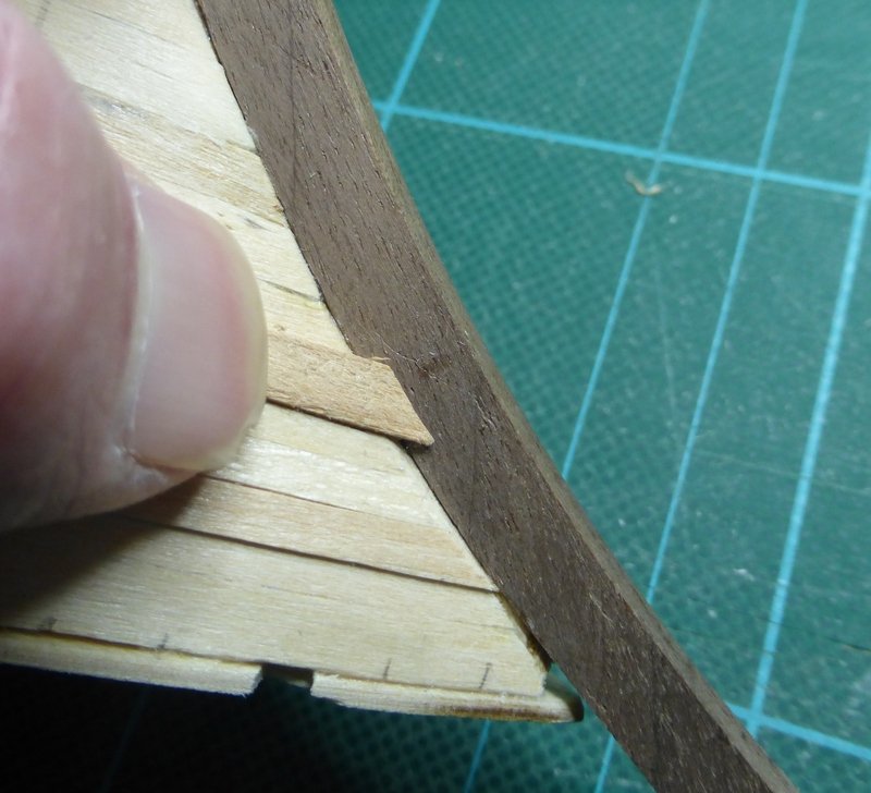
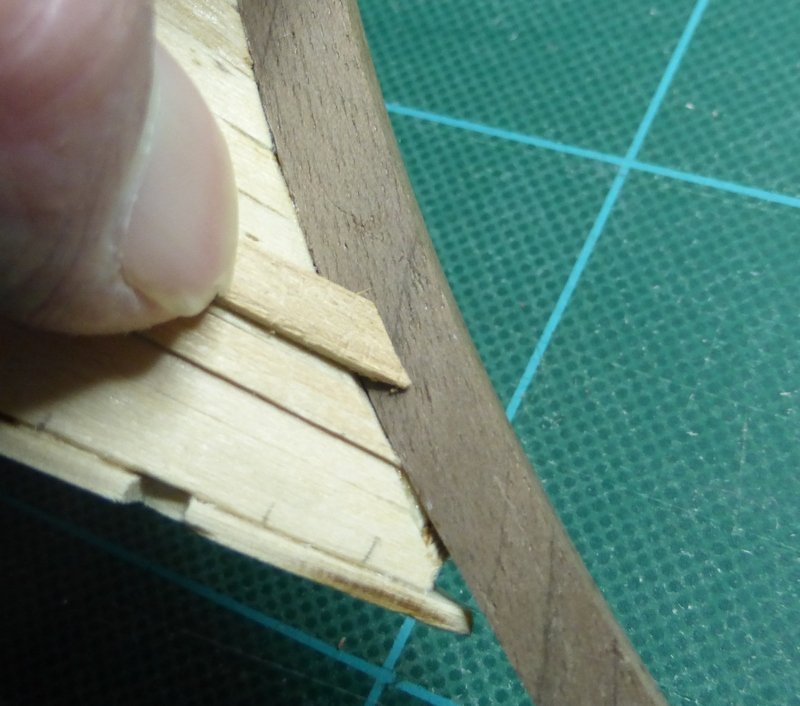
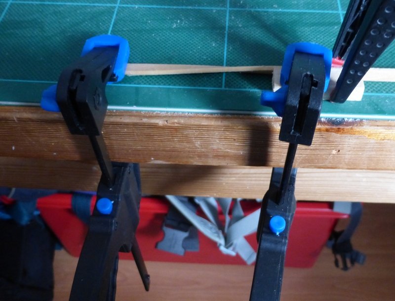
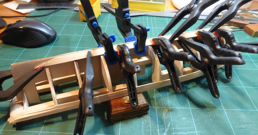
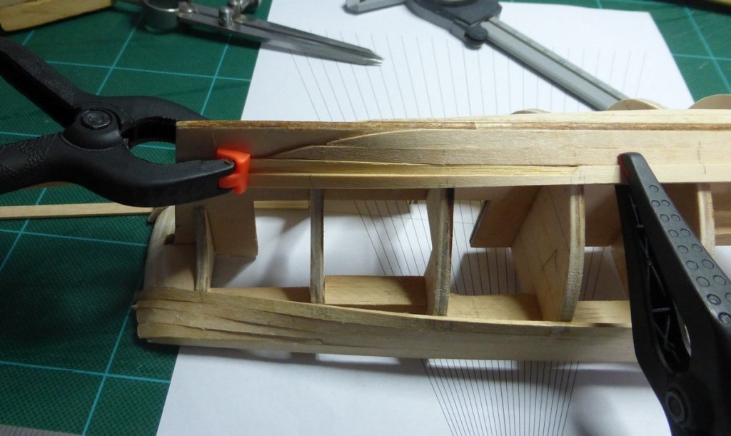
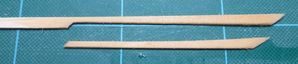
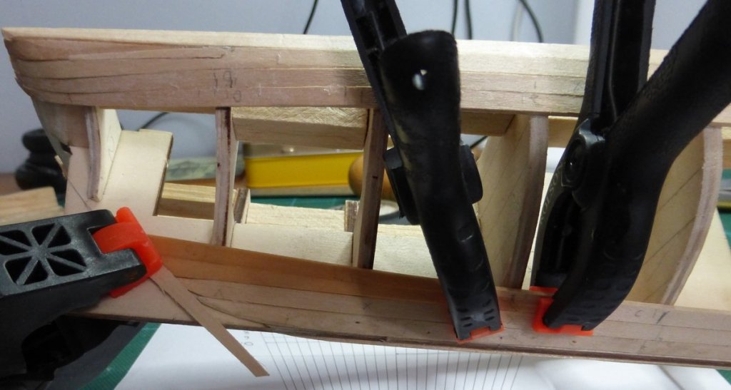
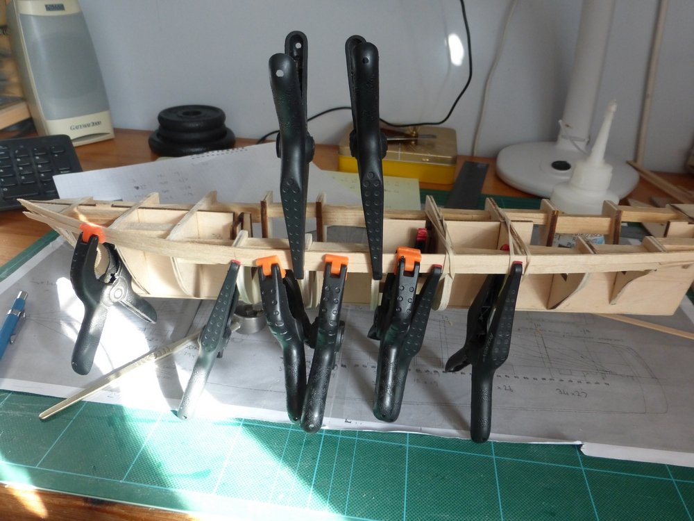
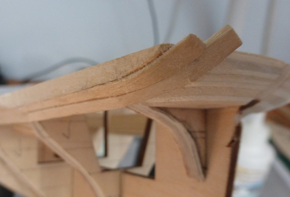
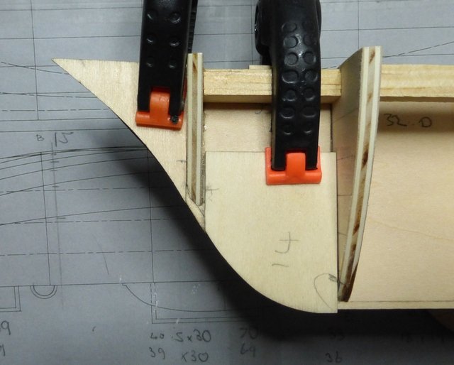
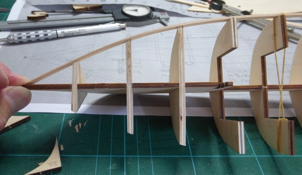
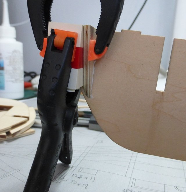
A quick update on progress. I have now fitted the top four and bottom 2 strakes, including the garboard strake, to each side. I will continue adding 2 strakes to the top for every one at the bottom and hope to meet around where the bilge goes into the side planking. So far it is going well and only a minimal amount of tidying up will be required. When it is required to bend the planks, I soak them in water and then clamp them to the required shape and let them dry. As there is always some spring back, if it is a really tight curve I over bend them slightly. These pictures show the garboard strake being over bent and its final shape before gluing. Gluing the second strake at the bottom. This is about as far as I have now got. The other side is the same. I like to take care with the first planking and try to use it to learn the run of the planks for the second planking. I also use it to find where stealers will be necessary and where there may be any difficulties. So far the main problems with the 1st planking have been the turn of the planks both from going from the side to underneath the stern counter and the sweep from the hull up over the stern counter. Currently I am fitting the next strakes each side at the bottom. I try to make them in pairs so the two sides match. This next strake at the bottom requires a stealer. I first cut the full length plank to shape using a rule to get a straight edge on the flat plank. I then position this on the hull with a thin piece of material underneath on which I can then draw the outline of the space left by the full length plank to make a template for the stealer. For this I am using some 0.6mm strip the same width as the planking material. This ensures the width of the stealer will be enough to fill the gap and I can insure it is fully pushed up to the adjacent plank. This picture shows the template in position for the outline to be drawn. Usually I do not use the clamps, but I could not hold everything in place and take the picture. I think the strip I am using for the template has moved slightly towards the left in the picture. As can be seen I am using a planking fan and dividers to mark out the widths of each plank to cut them to shape. Here is the end of the full length plank and stealer cut to shape. And here they are soaked and held in place with clamps while they dry out to the correct shape. Once dry I will glue them in place. Quite pleased with the fit. This also shows the tight bend over the stern counter. The top plank is vertical, the next plank goes from vertical to near horizontal in a few inches and there is a stealer in-between over the last two bulkheads. Once this strake is glued in place I will remeasure the length left on the stern frames and put them on my planking fan. Am enjoying this. Glenn
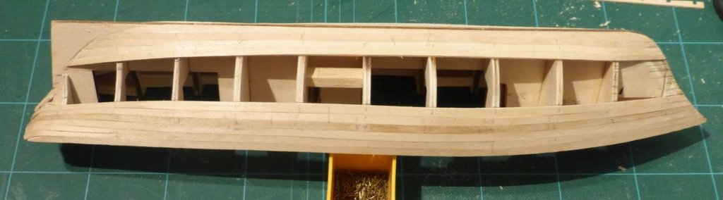
-
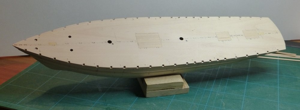
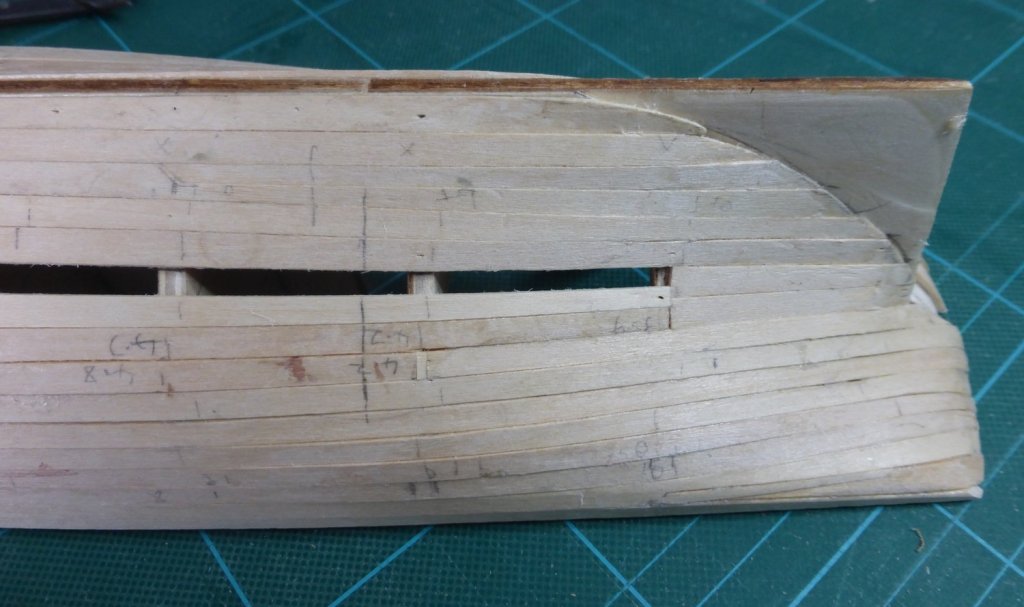
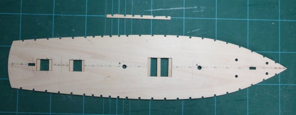
I have finished the filler blocks and have started planking. With the false deck held in place with elastic bands you can see that there is a gap between the edge of the false deck and the bulkheads. This width is about the thickness of the first planking. I say about because the planking does not always meet the deck at a right angle so the required width increases. The idea being that the second planking will go on something that is flush with the false deck and keel. The supplied planking is 1.5mm x 5mm. As you can see in the following picture of the stern, there are some very tight curves and the width of the planking must be reduced considerably to get round them. It is this that has caused me much concern in working out the run of the planking. In the end I have just decided to go for it and hope it all works out. Before starting I measured the length of all the frames on both sides. For this I use a flexible ruler pinched from one of my son’s project folders. Very useful for this. It was nice to see that, within the limits of accuracy that I can measure, the length of each frame was the same on both port and starboard sides. From this I could determine that 17 strakes are required in the centre on each side. Also near the bow the width will need to be reduced to an average of about 3mm on each strake. At the stern a number of stealers will be required, but there will also be some minor narrowing of the strakes before getting to that point. I will not bore you by reproducing the chart I have made. I now have the first two strakes on the port side in place. For the first strake I did not need to reduce the width at the bow. As it followed the natural curve of the hull it poked up over the bulkheads by the required amount, so I will sand it down to be level with the tops of the bulkheads once the first two strakes are in place on the starboard side. For the second strake I adjusted the width by taking a strip off the top and then sanded to fit. As this followed the natural curve of the hull it met the first strake while lying flat on the frames. Someone is smiling on me. However things are not so straight forward at the other end, so it all averages out. To get round that tight bend I inserted my first stealer. After fitting the first strake I sanded the end to shape and soaked some wood for the stealer. I then realised I had been over zealous on the sanding, forgetting about my gap around the top before the edge of the false deck. So after fitting the stealer there is now a gap that needs filling. Also the glue on the stealer dried with it at a slight twist. Not a problem on the first layer, but if it had been the second layer I would have removed it and had another go. That’s not a gap between the stealer and the second strake, it is a depression where the stealer got twisted. Rather than use filler, I will glue in an offcut of wood and sand it smooth. I will attempt something similar to replace the bit I erroneously sanded away at the end of the first strake. Next I will fit the first 2 strakes to the starboard side, taking care not to repeat my mistakes on the port side. Then move down to the keel and fit the garboard strake and the first strake after that, on each side. I prefer to make my mistakes on the first planking. A picture with all the clamps removed. I had noticed while typing this and looking at these pictures that the filler piece between the first and second bulkheads on the port side is missing. After a short search I found it had fallen down the gap between my workbench and the wall behind and was on the floor behind a stack of boxes. Out of sight out of mind. It appears that actually the next job is to fit the forgotten filler piece. I have also been thinking about the positions of the bulwark stanchions. It was Scottish practice that these were extensions of the frames. Now making an assumption that frames were at 16 inch centres, I marked every 3rd position on the false deck, which gave just over 20 stanchions. I then had a rethink and where the mainmast chainplates are I put them where every 2nd frame would be. No historical evidence that this was reinforced like this to resist the inward pull from the shrouds, but I thought this would make it more interesting. I will cut out the positions for these on the false deck before it is glued in place. There are now 23 stanchions on each side. Five positions at 3 frame intervals and then 2 more at 2 frame intervals. I did try and check this against the plans to see where deck beams may have been positioned, but there was no pattern that I could discern in the positioning of the hatches, companionways, skylight etc. Glenn
-
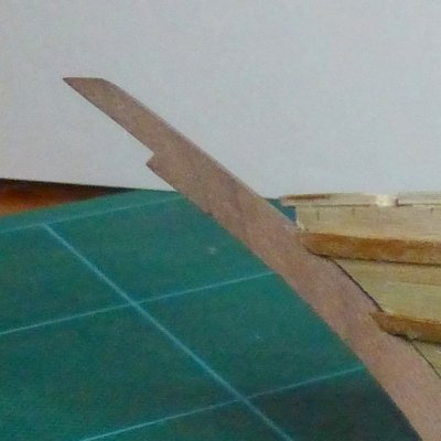
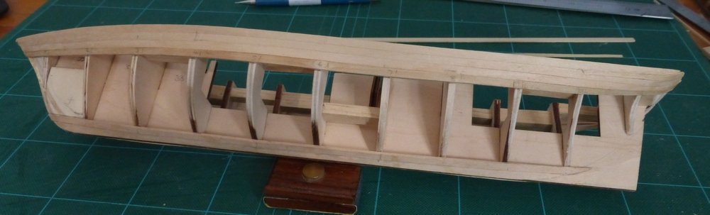
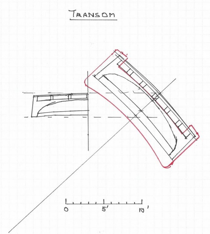
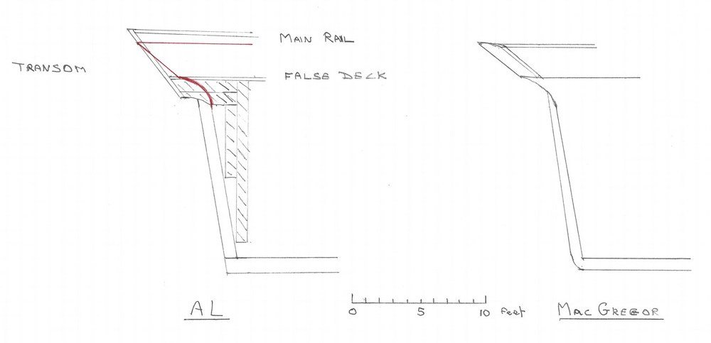
First thanks to everyone that has popped in and for the likes. I have been making steady, but slow, progress and have finally fitted all the bulkheads and started adding some of the supplied filling pieces. At the stem I have replaced the supplied filling pieces with balsa to fill the entire space and provide a better surface for glue in this critical area. As you can see in the picture above the 7th frames is a bit wonky. Do not know what happened there. I set it up, glued it, went away to let it dry, actually I went away for a week’s holiday, and when I came back the first think I noticed was the angle it was at. Luckily with the position it is in, it’s not critical and with some slight sanding I have left it as it is. I am pleased with how straight the keel is considering I have no sort of jig to hold it in while doing all this. I have not been able to get a picture to show it, but there is also no discernible twist in the hull and measurements show it is still as symmetrical as I could hope for. Still plenty of opportunity for all that to go wrong😀 Looking at the AL instructions I still do not understand how the planking at the stern works. The supplied transom looks too long, though maybe once glued in place some aggressive sanding could sort that out. At least that’s what it looks like in one of the coloured pictures in their instructions. So I compared the stern in the kit to the stern on the MacGregor plans, see below. This drawing shows the AL stern on the left, the shaded bits are the final bulkhead and some supplied filler pieces. The Red lines show where the MacGregor stern, as shown on the right, differs. I then compared the transom. The initial problem with this was that the MacGregor plans only showed a rear view of one side. I traced this off, projected this against a line at the angle of the transom to the waterline and using dividers to transfer the measurements sketched in what the transom would look like face on. When doing this it is important to get the angle of the line correct as small errors here can result in significant errors in the result. A good check is to ensure the length of the transom, along the line, is the same as shown on the side view in the plans. I have traced round the supplied part in the AL kit for comparison, shown in red. Sorry this was not quite central. I now have a better idea of how the stern works with the planking. Mmy stern will be more like the MacGregor plans than the AL kit, but in the end there will be some changes necessary so that it works with the model. The next task will be to complete the filler blocks at the stern to get the required shape then start the first planking. Along the way I will be giving some consideration to the bulwark stanchions. How many should there be and where would they be positioned. Glenn
-
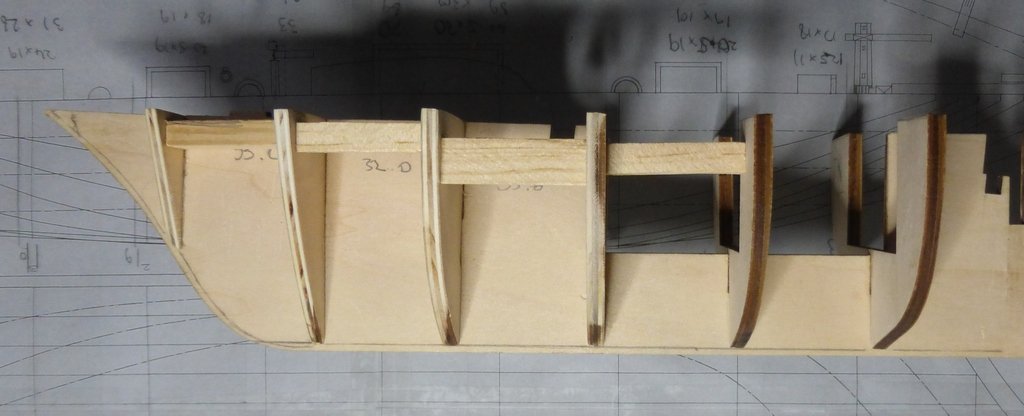
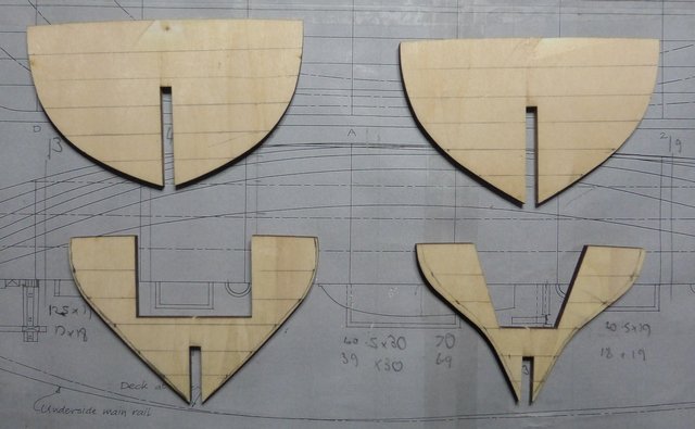
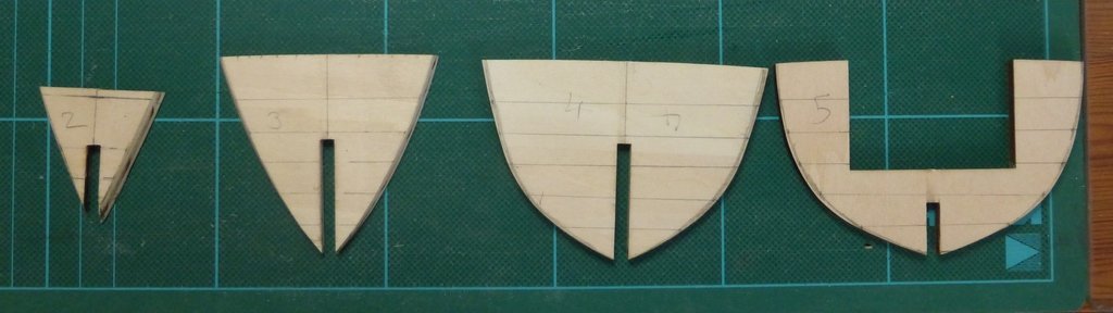
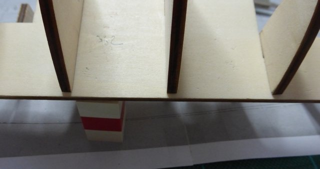
Pav, thanks for dropping in, I notice from your posts on other logs that you have also been working on a Scottish Maid. How is it going, finished yet? Not so sure it will be a breeze, there are plenty of issues still to work through. Sometime I get the impression I am over thinking this. geoffs, not sure about the Charles W Morgan being an AL build, try Model Shipways, though do not let that stop you dropping in for a look. I have been slowly making my way down the false keel, gluing on bulkheads, ensuring they are square, vertical and at the correct height. I had trouble with one of them as I was called away (when the admiral shouts jump, I say how high) just after I had applied the glue and fitted a bulkhead. When I got back the glue was dry enough that the bulkhead would not budge and it was about 0.5mm too high. I sanded off the top and added some thin strips to the bottom, difficult to tell which one it is now. It’s the 5th, the strips were walnut veneer, only about 1 inch was required each side and they have been sanded so that there is no step. As can be seen in the pictures, to make the structure more stable I have also been adding some reinforcement strips between the bulkheads. This is making the structure very ridged. I am cutting these slightly oversize then reducing them with the disc dander until they just slot into place, very careful that they do not slightly open the gap as they go in. This shows where the supplied filler pieces are supposed to go according to the AL instructions. The apparent overlap at the bottom is just a parallax problem. I am now getting to the rear bulkheads. This shows them being marked for fairing. The last frame is not present as this method cannot be used as the curves are too severe and there is not enough information on the plans. That one will have to be done by eye. There is very little fairing required on the first 2, but it is quite severe on the 4th of these. Also the curves on the last 2 are concave, so I will use a drum sanding attachment on the drill press for those sections. Glenn
-
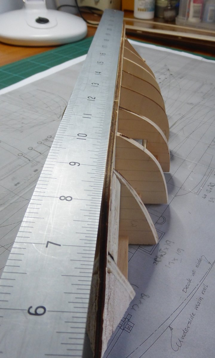
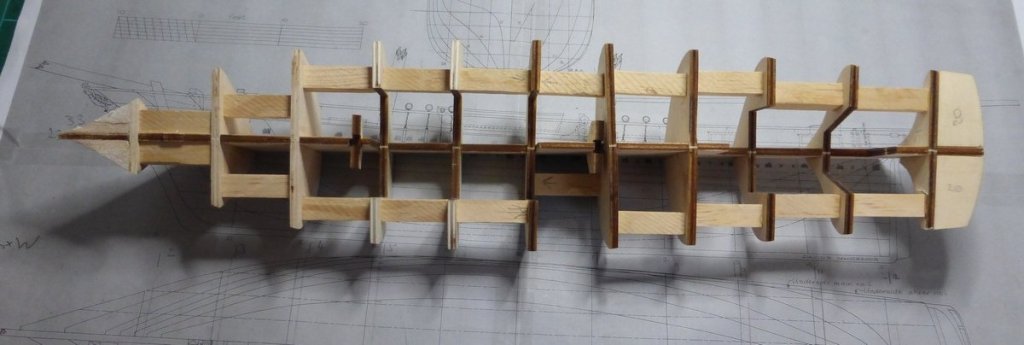
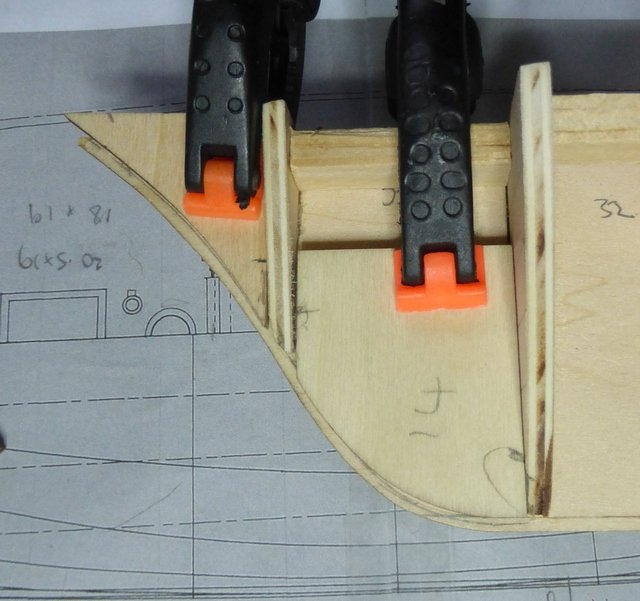
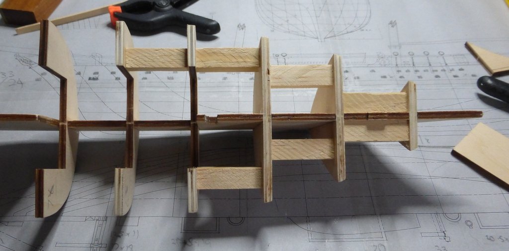
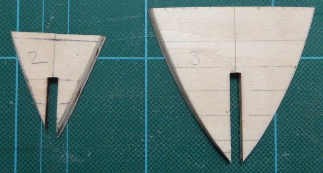
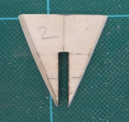
I have started on the hull. I cut out all the parts that form the framework for the hull. That is: the false keel, the false deck, bulkheads and various other filler pieces. These were quite accurately laser cut, but slightly too tight a fit. After sanding the faces of all the main components and cleaning up the slots with a needle file everything fitted a lot more easily, though still tight. For the fairing I started off using dividers to transfer the lines from the plans to the forward most bulkheads. Once I got past the first 3 the amount of fairing required was minimal, so I did the next one by eye. I then used a disk sander to remove the excess material. The following picture shows this with just the first 2 sanded. The next picture shows a close up of the first 2, part 2 needs a bit more work. During this process I ran into my first problem. The plans suggest doing the planking before attaching the walnut pieces (38, 39, 40 and 41) that form the sternpost keel and stem. I like the idea as sanding will be much easier without these parts in the way. However I cannot see how this works in practice. All the frames and filler pieces are intended to meet the edge of the false keel and the walnut pieces are 4mm thick, the same as the plywood that makes up the frame. That means the first planking, which is 1.5mm thick, will overlap where the stem and keel will go, the garboard plank will be a nightmare and I am not too sure what will happen where the deadwood would have been. I have looked at previous Scottish Maid logs but most do not show this very well, if at all. The only one that is of any help for this part of the build is by ‘JesseLee’. What I have decided is to lay the first planking so that it meets the edge of the false keel all the way round. This means reducing some of the filler pieces and mounting the bulkheads slightly higher. Not a problem with the bulkheads as they did not line up too well when pushed to the bottom of their slots in the false keel. The only bulkhead that really needed any change was part 2, which had to be moved up 1.5mm and the top taken off, along that line shown in the picture above. The rest of the bulkheads I will just glue leaving a gap for the garboard plank, as shown below. No glue yet. I have done the forward frames and checked how well the process is working. The following picture shows a dry run with the first 5 bulkheads. I must admit that I am surprised that this seems to have worked with no further adjustment being required. No matter where I put a baton along the frames it lays on all of them, there are no gaps, port and starboard. With everything going well the first glue has been applied and a bulkhead has been glued in place. That’s it for now, hopefully while I have been typing this the glue has dried enough and I can go back and glue the second bulkhead in place. Where would we be without Lego? Glenn
-
This book is subtitled ‘The last British sailing coasters’. I would recommend it to anyone interested in these vessels. Almost anything of interest is accompanied by detailed drawings, done by the author. There are 15 chapters: Introduction Shoes and ships and sealing wax Alert Brooklands Hulls and builders Anchors Deck fittings Variations in rig Masts, spars and standing rigging Sails and running rigging Engines Food Schooner models The vessels Conclusion The first 2 chapters provide a brief introduction, briefly describing the ships and the sort of trade they were involved in at the end of the age of sail. The next 2 chapters cover the times the author spent crewing 2 of these vessels. Interesting reading about life on these small craft, but more importantly for the model maker interesting details like what sails were set to leave and enter port. There is interesting detail like this throughout the book. Chapters 5 – 10 are then filled with just about every detail of these vessels the model maker could wish for. All supported by numerous drawings. For instance the chapter on deck fittings covers: the galley, companions, sidelights, dolly winches, water tanks, skylights steering gear, wheel houses, cargo gaff, pumps, boat, motor winch and hatches. With drawings of every detail and variations. I could write a lot more, but to put it simply these chapters contain all the details required to make a model at any normal scale. Possibly more details may be required for a model at 1/24 scale (hull 4 feet long) or larger. To emphasise it, I repeat there are drawings that accompany everything. Chapter 11 deals with the internal combustion engine. It does not deal with just the mechanics of an engine, but its effect on the trade supported by these vessels in terms of stockpiling and uncertain delivery dates and the way this affected the crew (more accurately the reduction in crew that this allowed). This brought about the end of the age of steam as well as being the final nail in the coffin for the pure sailing ship. It also details the effects an auxiliary engine had on the vessels themselves. To quote, ‘Topsail yards were sent down, flying jibs dispensed with, bowsprits cut short and topmasts, when not removed altogether cut down to short stumps…’. All things to bear in mind if making a model of a ship fitted with an auxiliary engine and much more. Chapter 12 deals with the diet on these vessels. Probably not that important to the model maker, but interesting. Chapter 13 is to me one of the most interesting in the book. It deals with how to take the lines of a vessel from a photograph. Obviously some photographs will be better than others. Ones taken when the vessel was light and the more photographs available the better. There is some deductive thinking involved which is all explained. Chapter 14 proceeds to list over 300 vessels that are potential subjects for models. Most of which just contain the minimum of details, however some contain pages of information. There are lines, deck and sail plans for 28 of these. They are reproduced at small scale, not sure how well they could be scaled up on a photocopier, but if they turned out fuzzy it should be possible to trace over the lines. Finally the conclusion gives some of the authors’ thoughts about where sailing ships will go from here. Time will tell. Altogether a very enjoyable read and well worth the small effort of obtaining a copy. Having got the book I think I would have liked to have paid more for a better copy, not that there is anything wrong with the copy I obtained, no torn pages just a few rounded corners; it still contains its library card. After reading this I feel I am well on the way to becoming an expert on schooners, though in reality I know that is not the case, just the effect of reading the book. I am sure a very reasonable model could be made from just the information contained within. The only problem being fitting it into the list. Would recommend to anyone interested in this type of small vessel. Glenn
-
- 5
-
-
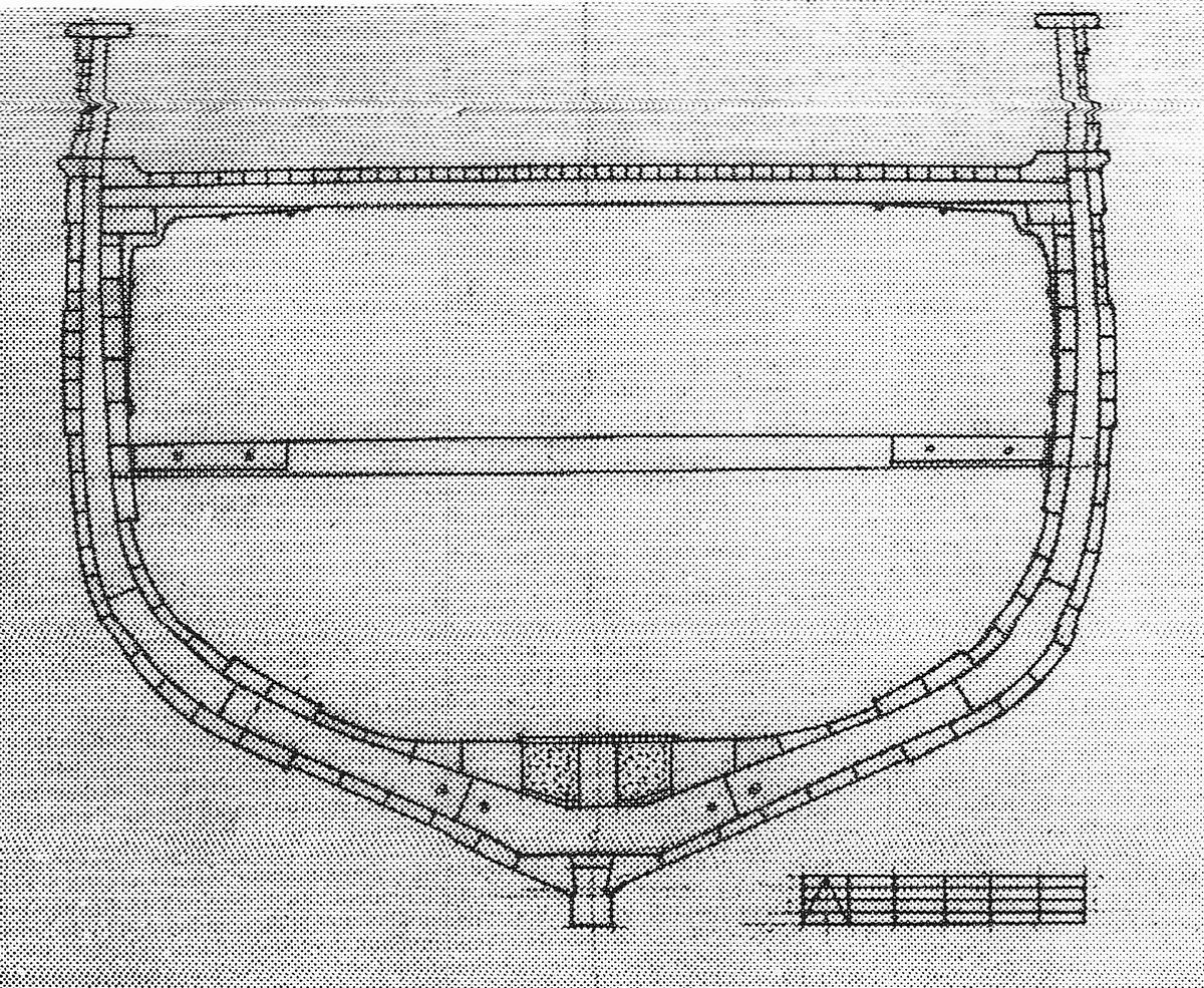
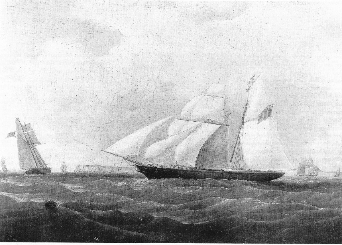
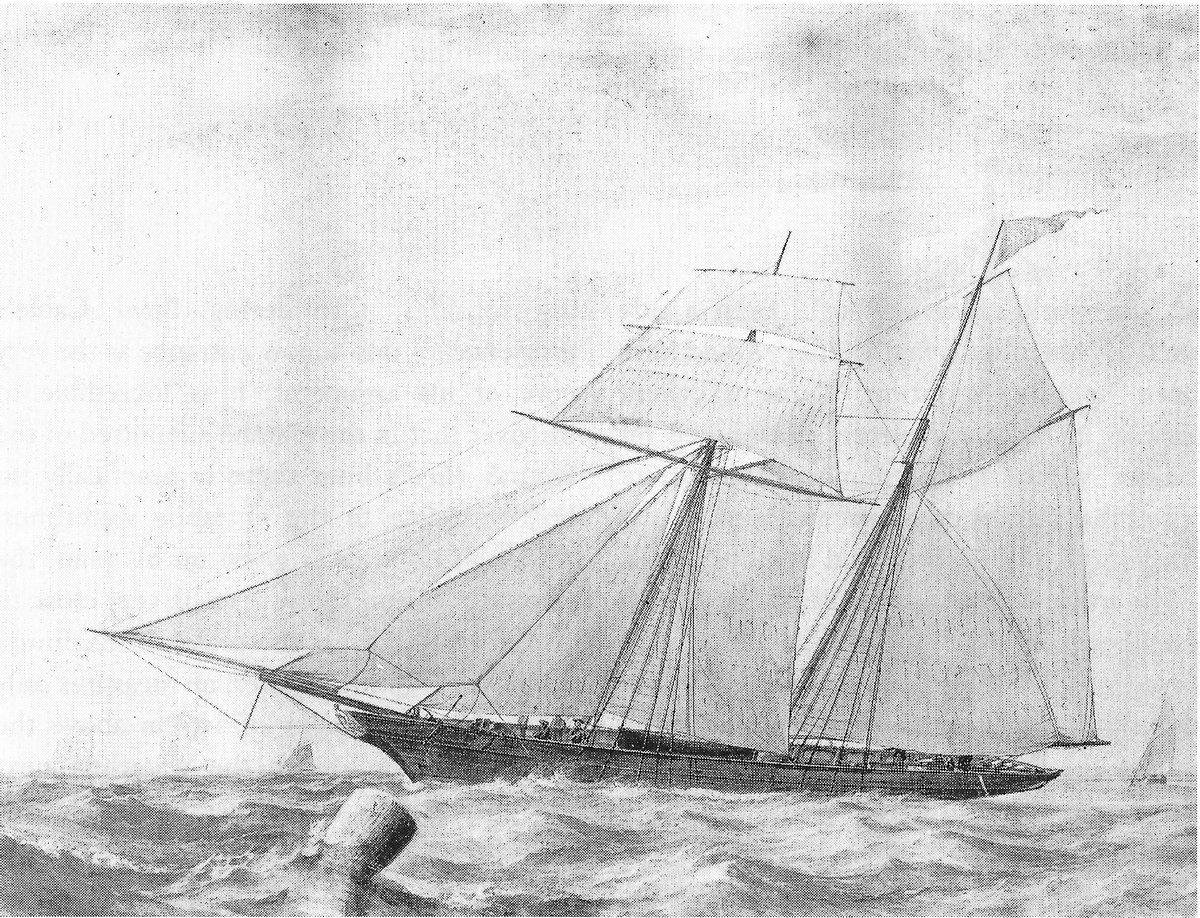
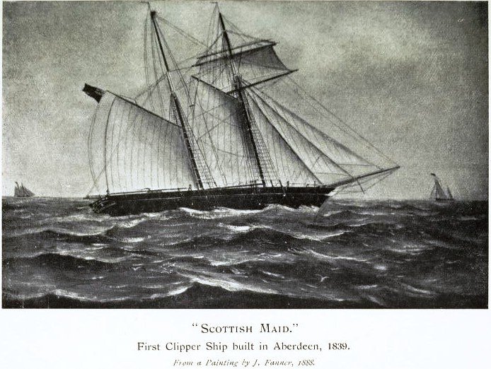
It has been almost a month since my last post. That is mainly because I have been working on the kitchen, which is now finished – hooray. However, I have also managed to devote quite a lot of time looking into the rigging for the Scottish maid. The Macgregor sail/rigging plan is based on the spar dimensions given in the builders cost account, a painting of the non-such (see below) and practice at the time. Also the plan just gives the basic outline of the running rigging with no indication of belay points. So for what is missing it is a case of relying on common practice. For this my primary guide has turned out to be ‘Schooner sunset’ by Douglas Bennet. I have just obtained a 2nd hand copy of this book; it was published in 2001. I will post a review in the forum: ‘Book and Magazine reviews and Downloads. Questions and Discussions for Books and Pubs’, sometime in the next few days. This book describes schooners of about 100 years later, but practice changed little in that time, the main differences arising from the end of piracy (in all its forms) and the introduction of steel standing rigging. I think a seaman who crewed the Scottish maid in 1839 would have had no trouble on the Alert (one of the ships detailed in the book, built in 1885) in the 1930’s. Looking at the Standing Rigging, there are only very minor differences between the MacGregor plans and the kit. If I am nit-picking, examples are: the fore stay should be brought down to the bowsprit bits. It could not be in the kit as they are not set far enough forward. Also in the kit the ratlines are spaced too far apart, but that is probably true of a lot of models, especially at smaller scales. The running rigging is where there are problems. It is important to sort this out before building the hull to ensure that there are sufficient points to tie off the running ends of lines and that they are where they are required. Looking at the kit plans I spot the following: Windlass 6 Foremast pin rack 6 Foremast port bulwarks pin rack 5 Foremast starboard bulwarks pin rack 5 Mainmast port bulwarks pin rack 7 Mainmast starboard bulwarks pin rack 7 Making a total of 36. I may have missed some. There appear to be no cleats anywhere, but they do also tie things a few lines off to handrails and eye pins. Before looking at what is required, a few comments about the rigging as detailed in the kit. There are a lot of mistakes. To give a couple of examples, all the head sails show the downhaul running from the tack point on the sail instead of the head and there are only single sheets, not port and starboard sheets. For the running rigging I will largely ignore the kit plans and go my own way. I am not trying to suggest they have everything wrong, there is a lot that is correct that I will do the same way. To identify what is required I have made a list of sails and their associated lines. This may net be complete/correct yet, all I am after at the moment is an approximate total. Also at this point I have not generated a plan for the belay points. Head Sails Line Belay point Flying Jib Halyard Pin rack Downhaul Windlass bar Port Sheet Bulwarks Starboard sheet Bulwarks Boom Jib Halyard Pin rack Downhaul Windlass bar Port Sheet Bulwarks Starboard sheet Bulwarks Standing Jib Halyard Pin rack Downhaul Windlass bar Port Sheet Bulwarks Starboard sheet Bulwarks Staysail Halyard Pin rack (1 reef band) Downhaul Windlass bar Port Sheet Bulwarks Starboard sheet Bulwarks As an alternative Hamby takes all the downhauls to cleats on the bowsprit near the bits. Topsails Line No. Lines Belay point Upper Topsail Sheets 2 foremast pin rack Clewline 2 Pin rack Buntlines 2 Pin rack Lower Topsail Sheets 2 foremast pin rack (2 reef bands) Clewline 2 Pin rack Buntlines 2 Pin rack Upper fore topsail yard Halyard 1 Pin rack Lifts 2 Pin rack Braces 2 Pin rack Lower fore topsail yard Halyard 1 Pin rack Lifts 2 Pin rack Braces 2 Pin rack Foreyard Lifts 2 Pin rack Braces 2 Pin rack Fore/Aft sails Line No. Lines Belay point Foresail Throat Halyard Pin rack. AL - Foremast boom sail. (3 reef bands) Peak Halyard Pin rack Sheet Pin rack Buntline Pin rack Jackyard Gaff Topsail Halyard Pin rack. AL - Mainmast gaff topsail Clewline (downhaul) Pin rack Sheet Pin rack Tack Pin rack Mainsail Throat Halyard Pin rack. AL - Mainmast boom sail (3 reef bands) Peak Halyard Pin rack Sheet Pin rack. AL - Boom Sheet Reef tackle AL - Mainmast boom sail sheet!!! Gaff downhaul Pin rack Topping lift Pin rack Main topmast staysail Halyard Pin rack Clewline (downhaul) Pin rack Port Sheet Pin rack Starboard Sheet Pin rack That is 60 lines that need tying off. However to this it is necessary to add some sails shown on the MacGregor plans that AL have chosen to leave out. Sail Line Belay point Square sail Port Yard rope Foremast Pin rack Starboard Yard rope Foremast Pin rack Port sheet Bulwarks Starboard sheet Bulwarks Upper topsail stunsail Halyard (Port and starboard) Downhaul Tack Forward Sheet Aft Sheet Lower topsail stunsail Halyard (Port and starboard) Downhaul Tack Forward Sheet Aft Sheet Squaresail stunsail Inner halyard (Port and starboard) Outer halyard Tack Forward Sheet Aft Sheet Downhaul Forward guy Aft guy Topping lift That’s another 42 lines and I have not included everything I can think of for the stunsails. Though it is possible that not all stunsail lines would have been taken down to the deck, they may have been tied off aloft. Also a few must be allowed for flag and signal halyards and there would always be a few spare. That is a lot of belay points. I am not sure at the moment how far I will go with rigging stunsails, my present thoughts are along the lines of the painting of the Pera (see below). But I think realistically I am looking at 70+ belay points. Which seems about right. Looking at a plan in ‘Schooner sunset’, there are about 9-12 to the port and starboard of each mast, 17 around the deck/masts and at least another 14 cleats and such like spread around the bulwarks, which gives a total of 67-78. Here are some low definition copies of the pictures commonly used as references for the rigging of the Scottish maid. Unfortunately these are the best copies I have. The first shows the ship herself, but as she was in 1888. Builders collection. This shows the Non-such, built in 1842, 3 years after the Scottish maid. Very similar in size rig and appearance. Close hauled under all plain sail. The length of the SM was 92.4’ nm and 142 tons nm, the NS was 98.6’ nm and 151 tons nm. No reference. It is interesting to note the reef pennants on the main sail. What I do not know is if, in those days, the mainsail would have had a boom tackle. If anyone can help it would be appreciated. This is the Pera, built in 1843. Note the wash ports, the Scottish maid would have had these. Two types were common, one hinged on the forward edge and one on the top. Vessels had an assortment of each. The Pera was 191 tons nm. Things to note, the foot of the square foresail is set on a boom and there are stunsails to each ofthe3 square sails. The reference in Fast Sailing Ships is the Science Museum, but I cannot find it in their catalogue. One final picture. This is the midship section of Swift, built 1843, 183 tons nm. The original is from the Lloyds register survey report in the NMM. It shows the sort of construction from Alexander Hall & Sons in those years and is likely to be very similar to the Scottish Maid. Note the thicker planks in the bilges and the wales. According to the Lloyds register survey report for the Scottish Maid’s scantlings, keel to bilge and bilge to wales 3in, bilges 4.5in, wales 4in and topsides 2.5in. I think I have done enough research to start building. However before that there is one more task, I have to clean what is referred to in the house as 'The Hobbies Room'. My wife is still not sure how she ended up with one of these. It seemed to have arrived with me when we got married almost 25 years ago. This means a thorough clean. Empty the room, clean the floor walls and ceiling. Then finally only items that have been cleaned will be allowed back in. Sounds to me like a return to the days of Nelsons Navy. Glenn


-
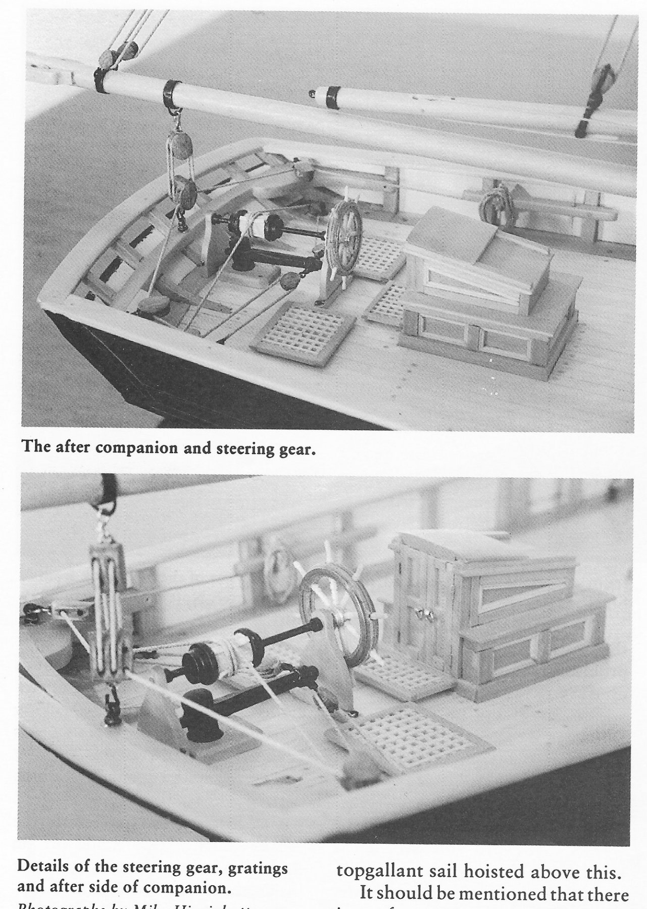
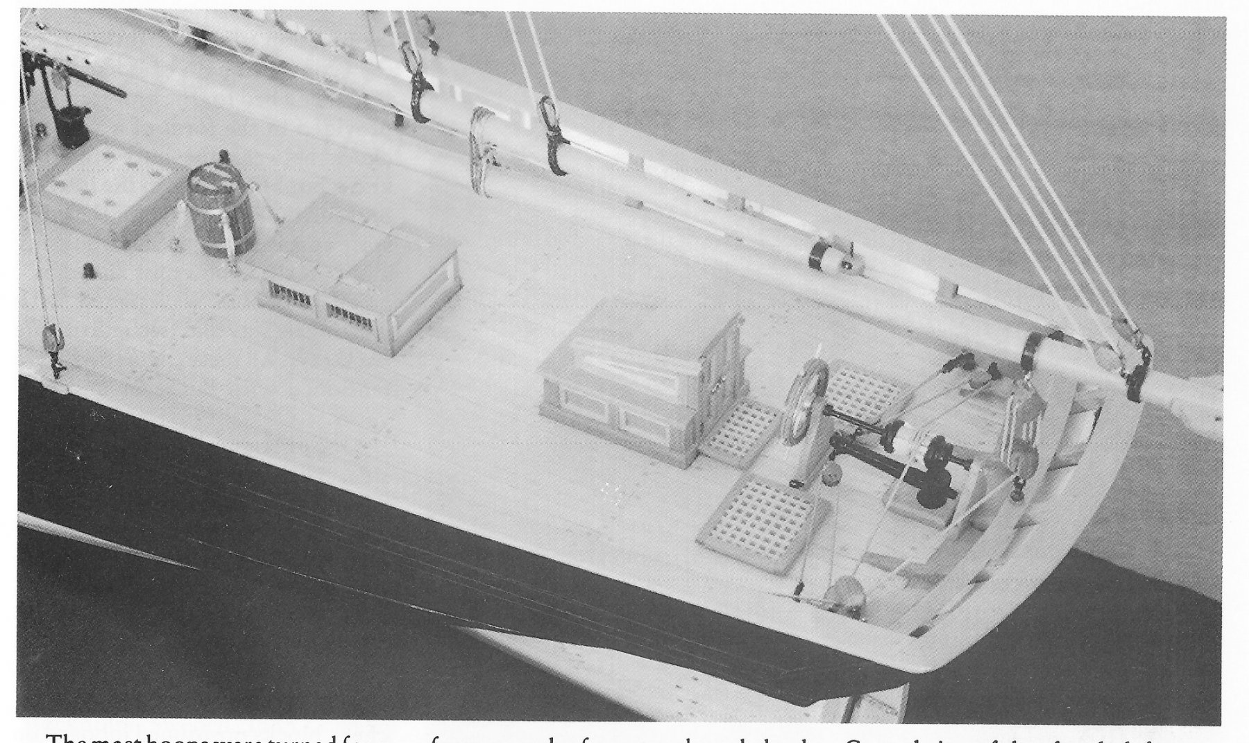
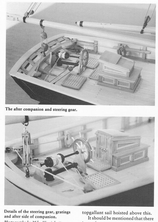
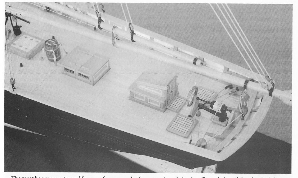
Here are a couple of pictures from Model Shipwright 94 of the model by D Hamby showing his implementation of the steering gear and the main sheet. This is fairly standard. The sheet is double ended so the starboard will be the mirror image of the port. Hope you find these useful. Glenn
- 115 replies
-
- 5
-
-
- Scottish Maid
- artesania latina
- (and 1 more)
-
I live in the UK. Where can I purchase your kits?
-
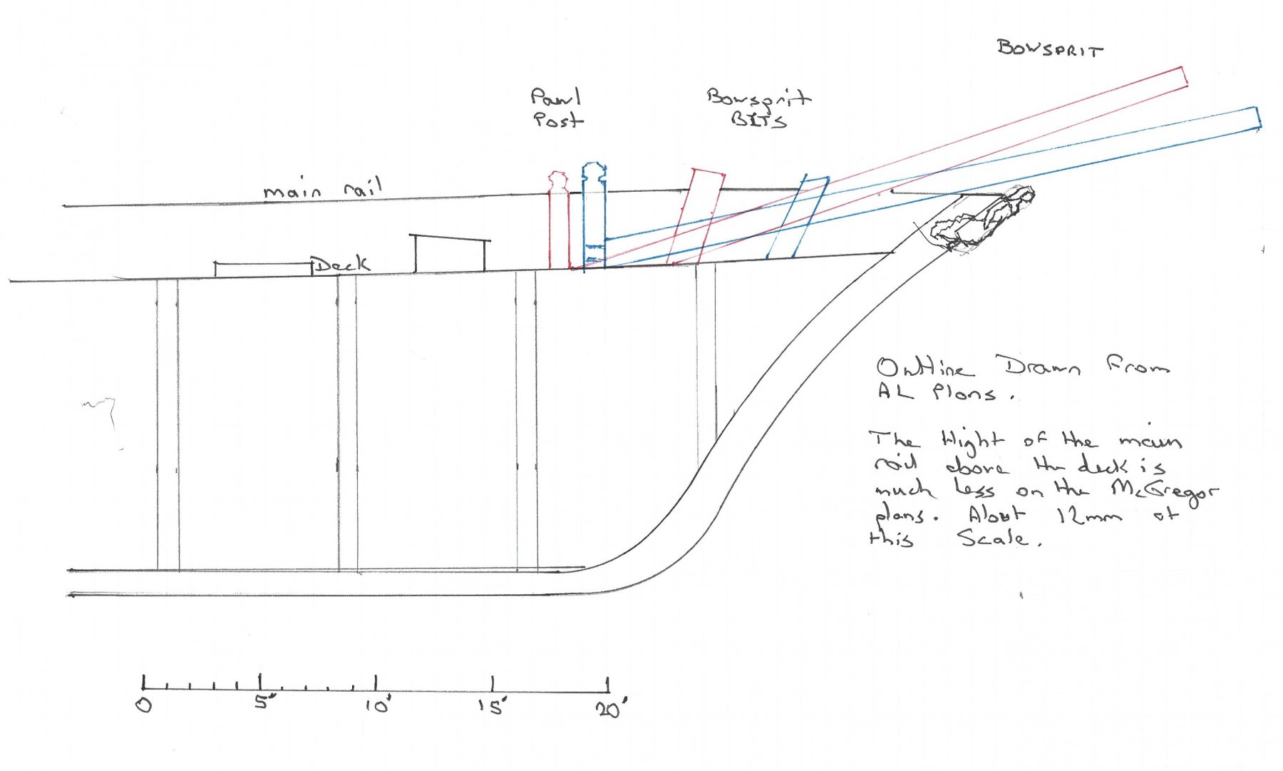
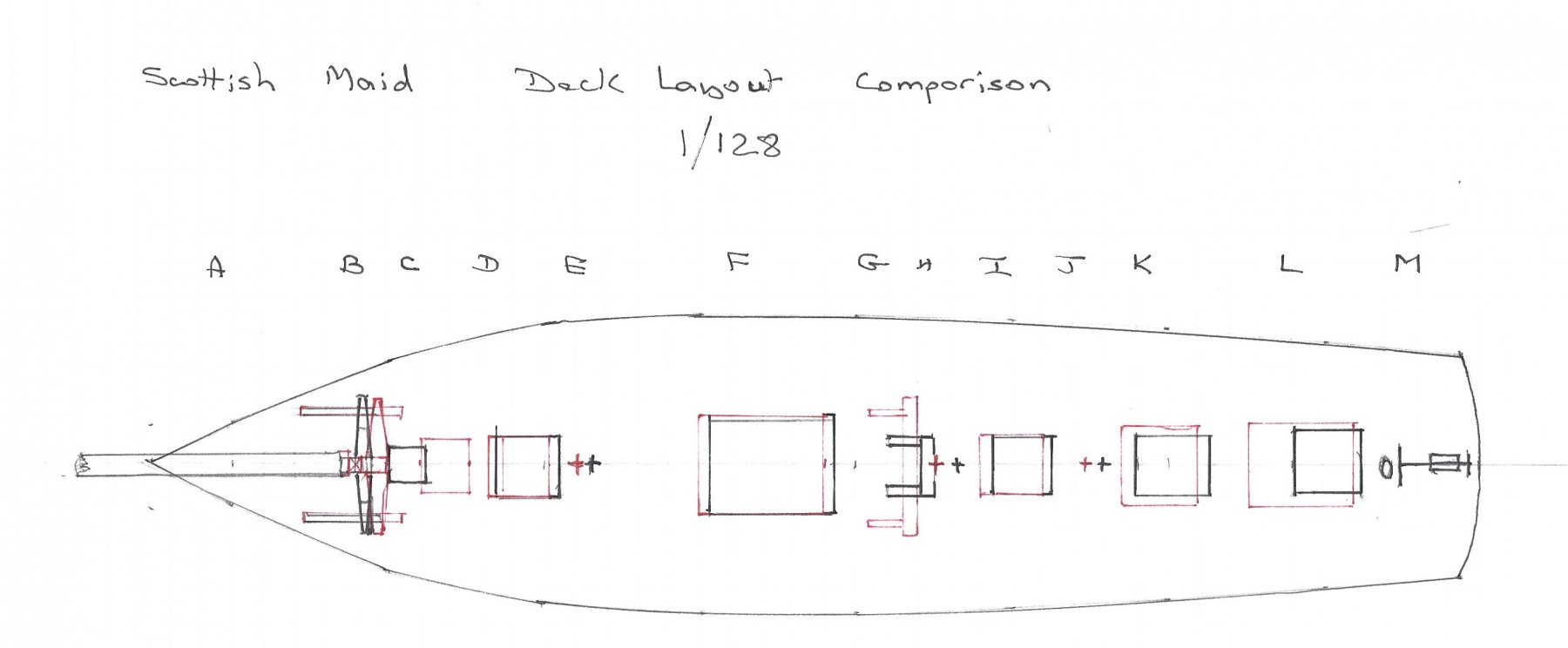
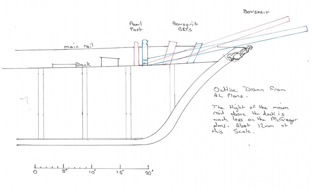
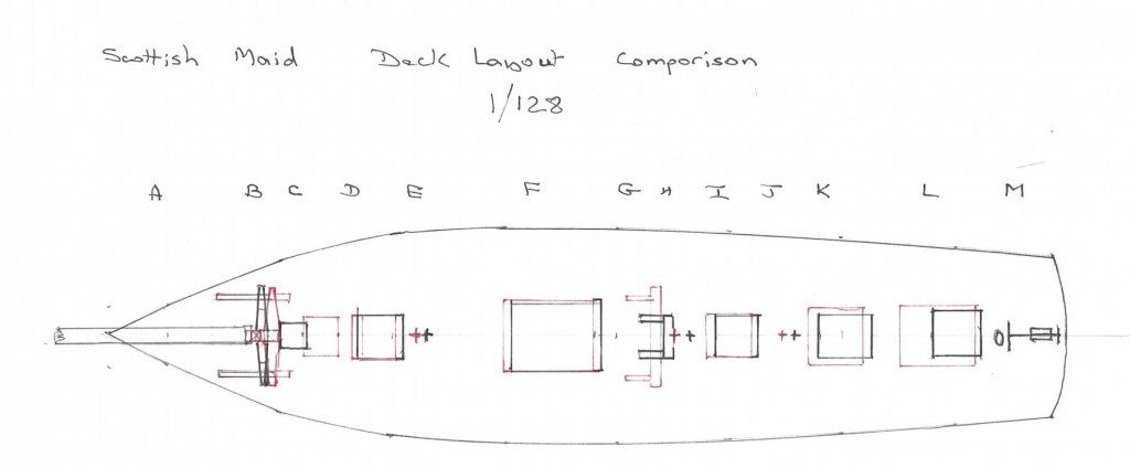
Between household chores, such as decorating the kitchen, I have found time to compare the Hull and masts/spars of the AL model to the MacGregor plans. The most obvious difference between the MacGregor plans and the kit is the angle of the Bowsprit from the waterline. In the kit this is about 16.5 degrees, where on the MacGregor plans it is about 11.5 degrees. This is quite significant as it affects all the rigging for the bowsprit and the jig boom. This is especially noticeable when looking at the bobstay. It makes it difficult to make this tight. Indeed if you look at the example model on their web site and the pictures on the box it looks like this. Sorry about the quality, it’s the best I could easily do. If the MacGregor plans are correct, the bowsprit should be almost parting the figurehead’s hair. More on the bowsprit later. I looked at the MacGregor sheer plan and compared it with the model. I found the model to be an excellent match to the 1/64 scale plan. Nothing wrong here. Looking at the stations on the sheer profile, they are drawn in every 8 feet. AL have used these as the positions for the bulkheads on the model. Obviously saving the draftsman a lot of time and trouble. The rearmost 5 bulkheads are placed aft of these lines and the forward 5 are placed forward of these lines. That leaves 1 more the midship frame which has been moved slightly to even up the gaps. Again this is not a problem as the shape of the hull does not change in this area. Placing the laser cut bulkheads on the body plan shows there is almost no error. Looking at the lengths of the masts and spars there is a very good match, there is an average error of about 1%. The spar that differs the most is the bowsprit, not because of its length, it is about 5mm too short on the model, measuring from the pawl post, but because of how it is mounted and its angle. The following sketch illustrates this. AL Model is shown in red, MacGregor plans in blue. For a start the MacGregor plans show the bowsprit mounted slightly further forward. Then the pawl post has a square mortise cut on its fore side for the heel tenon of the bowsprit. The AL plans show the bowsprit ‘scarfed’ to the deck which has the obvious effect of lowering this end. The bowsprit then passes through a pair of bowsprit bitts which are mounted much further forward on the MacGregor plans, as shown. In his article Hamby added a bed for the bowsprit between these in the form of a wooden chock. Also given their position he also used these as an anchor for the lower end of the forestay. The MacGregor plans are not detailed enough to suggest how this was actually secured. When it comes to the deck layout there are some changes. The following drawing shows a sketch of the MacGregor plan in black, overlaid with that of the model in red. I actually drew this to scale on 5mm graph paper, but unfortunately that has not come out in the scan. I should have added a scale bar, as I did for the bowsprit. A. Bowsprit B. Windlass C. Forward companionway D. Forward cargo hatch E. Foremast F. Main cargo hatch G. Winch H. Mainmast I. Aft cargo hatch J. Barrel K. Skylight L. Aft companionway M. Steering gear, with binnacle in front. The main differences are the size of the aft companionway which is much larger on the model. This has the effect of pushing forward everything forward of it. Then the position of the forward companionway is much closer to the windlass, giving a reasonable gap between it and the forward cargo hatch and actually allowing access, probably to the crew’s quarters. On the model they are so close it would be impossible to open the door fully. That’s about it for the hull and masts, though I am sure I will spot other differences as I progress. Next time the rigging. Glenn

-
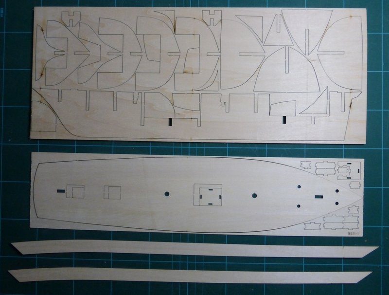
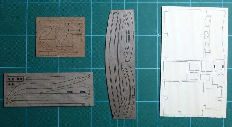
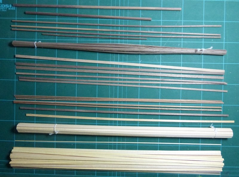
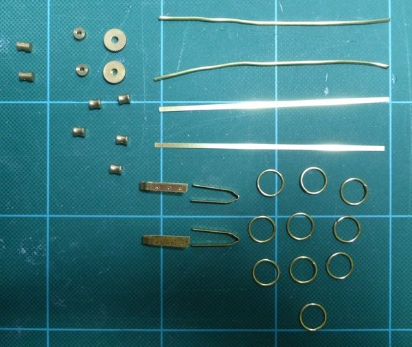
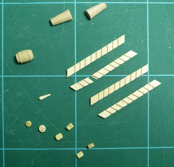
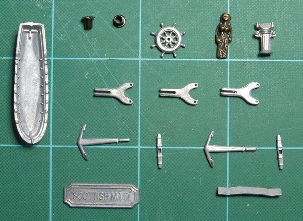
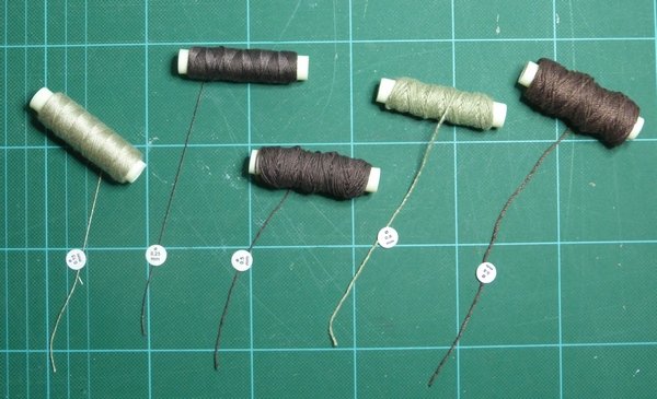
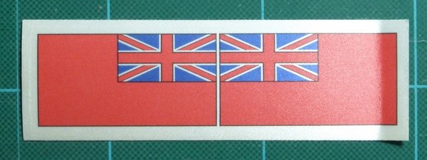
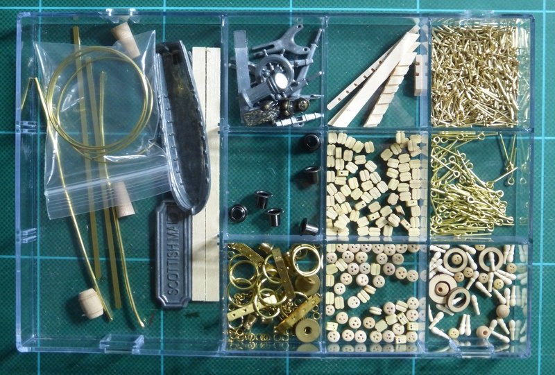
A quick look at what is contained in the box. 3 large sheets of laser cut parts from 4mm plywood and 1.5mm plywood. All very neat with clean edges and not too much burn. The 4mm ply containing the frames is as flat as could be hoped for. 4 small sheets of laser cut parts. 2 Walnut, 1 sapelly and 1 1.5mm ply. Again all neat with very little burn. Not heard of a wood called sapelly before. Maybe something has got lost in translation. Strip wood. Starting with walnut dowels at the top, then walnut strip. Then the first planking strips (in a bundle) described as Samba in the parts list, looks like European lime. Then finally a large bunch of Mukali for deck planking etc. Edges of all strips are clean with no splintering. Mostly good quality except that bundle of 0.6mm walnut. This was obviously cut from wood with a knot, so quite a lot of material to be cut out. This might have been a problem if I actually planned to use these to plank the hull. There is a tale to tell about the large bundle of Mukali. This is 5mm x 0.6mm strip to be used for a whole host of parts including deck planking. When I got the kit, for Christmas, I checked the parts supplied against the parts list and there was none of this present. On the 29th of December I sent a message to AL using a box I found on their web site. On the same day I received a response giving instructions about how to proceed to request missing parts. As it took a bit of time to collate the information required I responded to this email on 4th January and again received a response the same day that the parts would be sent. I received the parts through the post from Spain on 7th January and sent them a thank you email to let them know I had received this. There was about 3 times as much as would normally have been present in the kit, about a handful. I will probably never ever run out of 5mm x 0.6 Mukali strip. However as for using it for deck planking on this model, I think not, though it is of good quality and will be used elsewhere. Its just that I want to plank with something a bit thicker and narrower. Various brass bits, most of which will not be used. Those 2 very bent pieces of 0.75 mm at the top right are meant to be used for railings!!! Examples of various wooden fittings. These are generally good except for the sides of the ladders. These are about 0.1 inch thick equivalent to about 6 ½ inches. That is some ladder. Various moulded metal parts. I will probably only use the figure head, the binnacle and the name plate. Rigging cord. Nice to have it in 5 sizes. Unfortunately this is the worst quality product in the kit. It is more like something my mother would have knitted with. This will go in the household string draw. Luckily I have plenty of suitable spare rigging cord. A flag. Under closer inspection this was better than first thought. The jury is still out on this one. All the bits and pieces came in a nice box. Finally something to make the sails from. This is much too heavy to consider using. Also I like what Tim Curtis is doing with paper on his model and will try and emulate that. That’s it except for the instructions and drawings. If anyone is interested in these examples are available on the AL web site. I have not yet compared, in detail, what comes with the kit to the MacGregor plans, that is my next task. A cursory glance shows they are similar. I suspect the differences will be in the detail. I suspect, without measuring, that the AL kit has the bowsprit at the wrong angle. Also just looking at the AL drawings the running rigging looks a mess. I will get on with that using whatever spare time I get from doing up the kitchen and cleaning out the workshop. Glenn
-
What you have done so far looks good. What I would suggest, if you have not done this already, is go to the home page, click on 'Articles Database', near the top and then look at the 'Framing and Planking' section. There is an article titled 'Simple Hull Planking For Beginners'. In my opinion any article that is 40 pages long is not a simple guide for beginners, but if you look through this it should point out most of the pitfalls. Look at pages 21 and 22 before proceeding any further. As a beginner any time you spend looking around this area is probably time well spent. You are using the same method I use for bending planks. Soak them, clamp them in place and let them dry before gluing them. It may be obvious, but it is important to let them dry before gluing, wood expands when wet and contracts as it dries. It is important to glue the edges. As you go down the hull and it curves more you will need to bevel the edges to maintain contact over the entire width. Sorry that I do not have any pictures of my build of this model, if digital photography had been invented then it would have been in its infancy. Glenn
-
Those of you paying attention to the title may have noticed that I have given the scale as 1/64, where the AL kit is marketed as 1/50. Why the difference? This first came to light when I compared the plans I had obtained from the Brunel Institute with the parts in the kit. It appeared that the parts supplied were a few inches too short for a 1/50 scale model. Where was the mistake? I checked the dimensions of the plans and the scale bars were correct: 10 feet was equivalent to 2.4 inches. Next I got out the MacGregor book ‘Fast Sailing Ships’ and checked the size of the Scottish maid. Now the exact size is not known for certain but according to the builders certificate the length is 92.4ft nm. At 1/50th scale this would give a hull length of about 22.2 inches between the aft side of the stem and the fore side of the sternpost. Using just the parts of the model it is difficult to get an accurate measurement. But I would give this dimension as 16.4 inches for the model. This actually gives a scale of about 1/67, but I have chosen 1/64 as that is the nearest commonly used scale. Also other measurements, such as the distance between masts, give slightly different results. I feel cheated I have purchased a 1/50th scale kit which should have a hull 22.2 inches long (nm) and instead only have a hull which is 16.4 inches long (nm). I feel cheated out of 5.8 inches of hull. I suppose it does give the dimensions of the model on the box, but I wanted to make a 1/50 scale model not a 1/64 scale model (grumble, grumble). Well, I suppose I have what I have. The only way to get a 1/50 scale model would be to throw away the kit and scratch build. I could not bring myself to do this, too much waste, so I will just get on with it. Apart from that the Admiral would keel haul me if she knew I had spent about £90 on a kit and had then binned it. I did think seriously of scratch building this. In the end I went for a kit as it would give me everything I needed to get started in one easily purchased package. There is very little in the kit that could not easily be made from scratch. Also in general the material in the kit is of good quality, especially the wood. The majority of which is cleanly cut and as flat as could be hoped for. There are some Items I will be replacing, but aren’t there always. The primary reference material that I will use for this build in addition to what is supplied with the kit is: · David R MacGregor, Fast sailing Ships, Conway 1973 & 1988. · David R MacGregor, Lines & Deck plan, Sail plan, Brunel Institute · T W Ward, Reconstructed drawing of Scottish Maid unloading at a London wharf, Brunel Institute · D Hamby, Scottish Maid A nineteenth century packet schooner, MS 94, 1995 · J G Heard MD, The English merchant schooner Scottish Maid NRJ Volume 58 No 4, 2013 The Hamby model is built to a scale of 1/48 and the Heard Model to a scale of 1/96. Neither have sails and they portray the ship quite differently. Lack of sails is useful when using pictures for reference as details of the models can be seen more easily. I will be including sails on my model. In my next post I will run through what is in the kit and my first impressions. Glenn
-
Forgot to say. The deck should not be flat. it curves to allow water to drain. Glenn
-
This was my first ever ship build as well, a long time ago. I am looking at the model as I type this. Wish you well and I will look in to watch your progress and bring back memories. I learnt a lot on this build. Glenn
-
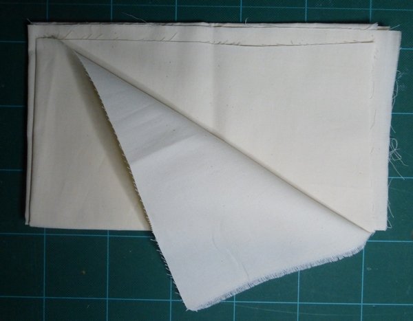
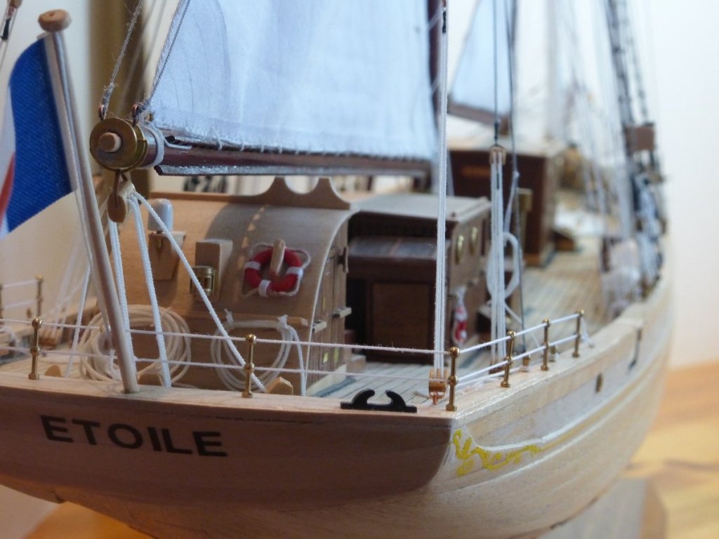
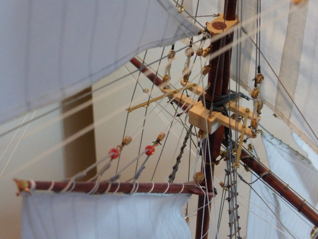
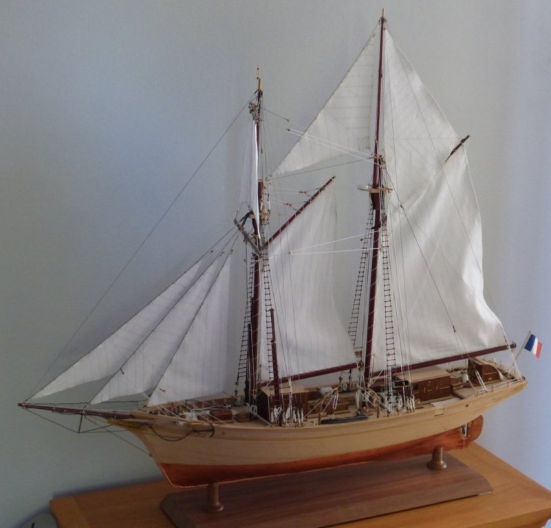
Not a lot to say, again thanks for all the kind comments, the likes and to anyone for just dropping in. Here are the final pictures as promised. There will however be a slight delay before starting on the next model. I am under orders, from the Admiral, to give the hobbies room a thorough scrub. It must shine like guardsmen's buttons before I am finished. At the same time I will also be giving the kitchen a face lift. New lights, fittings, floor, etc. Paint the door etc. With this delay and my visit to the Brunel institute just over a week away, It is now almost certain that I will be starting the Scottish maid next. so please keep an eye out for that. Glenn


- 101 replies
-
- 9
-
-
- L Toile
- Billing Boats
- (and 1 more)
-
It has been some time since my last post. Mainly because of all the troubles I have had making a stand, but also because I have been spending most of my spare time for the last 2+ weeks marking exam papers. First I would like to thank Michael, Tim, Popeye and Eric for your kind comments, as well as anyone else who has just looked in. Also I would like to thank everyone who has made a comment or just looked in throughout the build. I really appreciated all the encouragement and support throughout. Popeye has asked, so: For my next project I currently have two options. My first is the Caldercraft Snake, which I started a long time ago, but unfortunately life got in the way and it was shelved. Then, in Feb 2017, just as I was preparing to restart I got given this kit and decided to do it first. So by rights it should be the Snake next. However At Christmas I received the Scottish Maid kit by AL, which is a topsail schooner as was the Etoile, which I have really enjoyed building. So a dilemma. I would really like to get back to the Snake, as I have hardly started it. But it may take years; it is a much bigger job than the Scottish Maid. So I guess it will be the Scottish maid. With this in mind, as a possibility, a few months ago I got in touch with the SS Great Britain trust and have arranged to visit their archives and examine the plans of the Scottish Maid in the McGregor collection. This visit will take place in about 3 weeks’ time, so nothing will happen with the Scottish maid until then. So that seems like it is decided, the Scottish Maid, but I really do want to get back to the Snake. I feel if I leave it too long that will be it. Maybe I could do some work on the Snake first. Aanother option is to work on both in parallel, Hmmm. Above I said I had problems with the stand. This was almost a series of disasters, but it worked out alright in the end, after frequent visits to the local hardware shop for some MDF, glue and screws. If only I had worked out everything before I started I may have only needed a single trip instead of 3. A tip. Never use spray contact adhesive for veneer. The chap in the shop must have seen me coming: “Yes sir, this is just what you need and it’s on special offer we’re almost giving it away” (because it’s useless). I had also been waiting to make this post until I had some pictures to go with it. Unfortunately I have just downloaded them and they are not good. I think it was lack of light. I will have to try again sometime. However this is about the best one. At least it shows the model on its stand. Looking at this not sure if the colour of the wood is right, but have not thought this when looking at the real thing. I think a brass plaque is needed. What I enjoyed most with this build was doing the metalwork, which basically meant just giving it a go and seeing how it turned out. I have always enjoyed metalwork though I have not had the opportunity of doing any for years. What was least enjoyable was doing the rope coils. Also it was my first go at coppering and I was not happy with the results, though I learnt a lot in the process. I will try and take some better pictures and when I post them I will change the title to finished. Please look out for my next log, still not 100% sure what it will be. Glenn
- 101 replies
-
- 9
-
-
- L Toile
- Billing Boats
- (and 1 more)