glennreader
-
Posts
136 -
Joined
-
Last visited
Content Type
Profiles
Forums
Gallery
Events
Everything posted by glennreader
-
 Tim, Totally concur with Michael. I think these furled sails are excellant, you have got the scale just right. I espeshally like the way the gaff sail looks, just the right amount of bulk in the furled sail. Regards
- 115 replies
-
- 1
-

-
- Scottish Maid
- artesania latina
- (and 1 more)
-
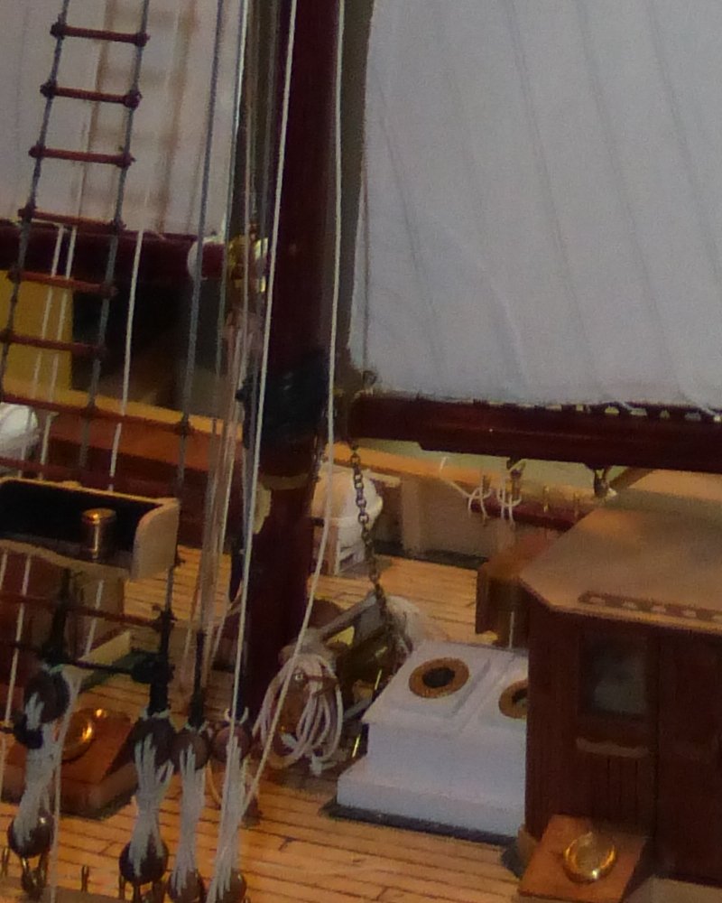
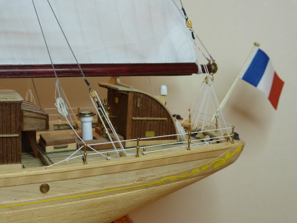
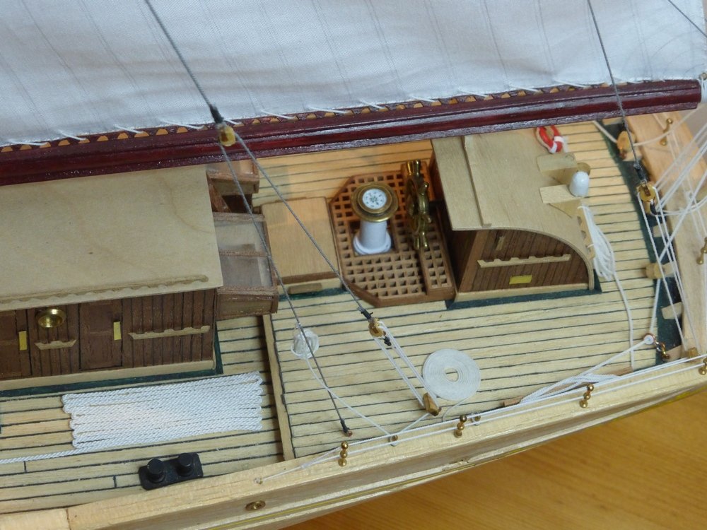
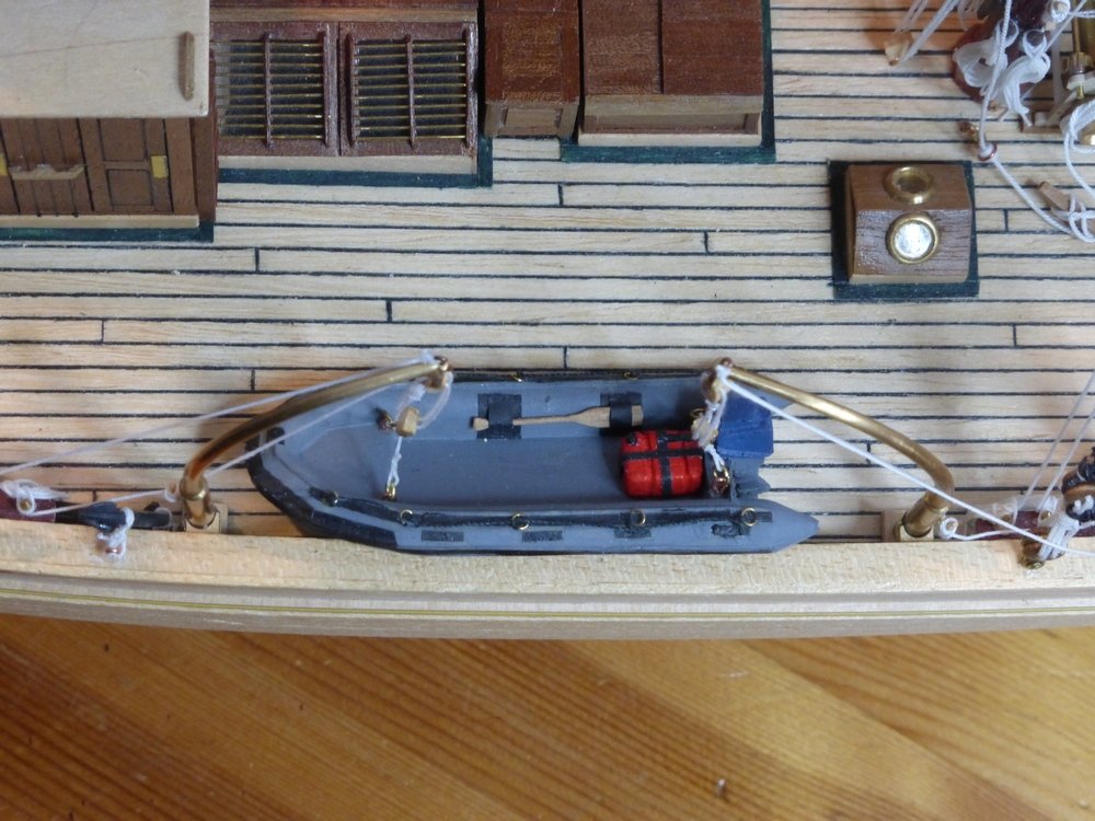
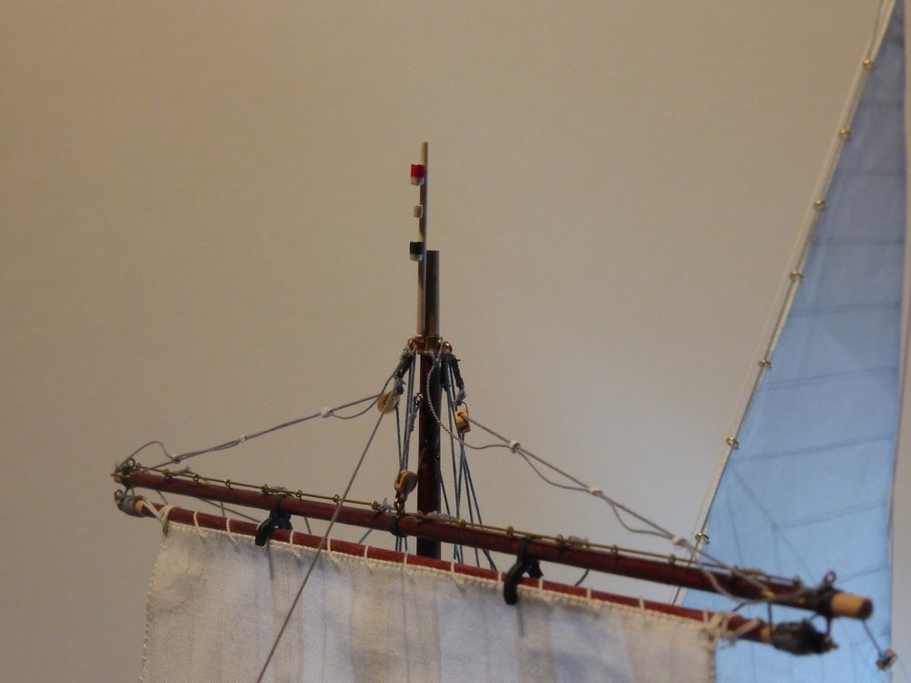
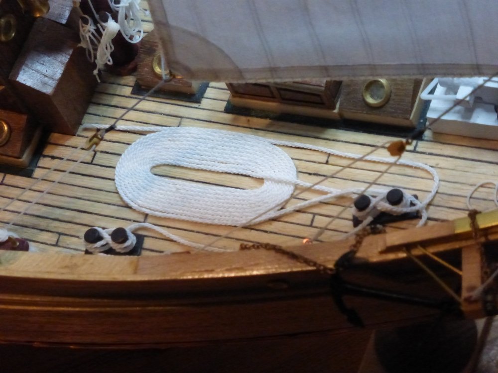
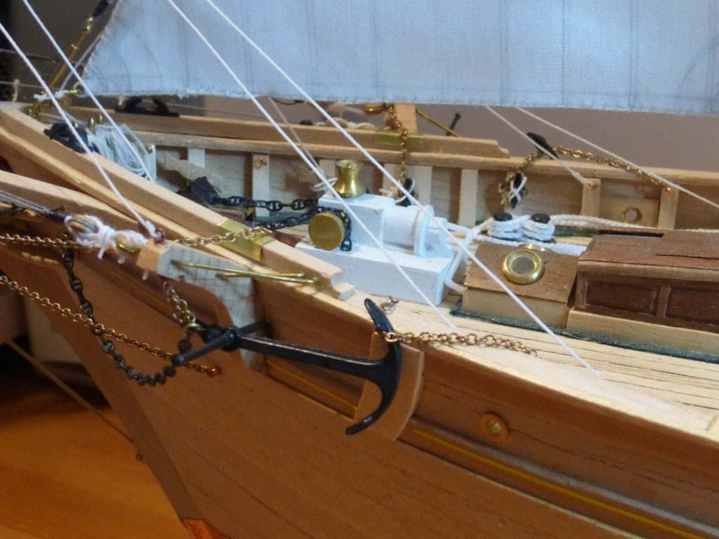
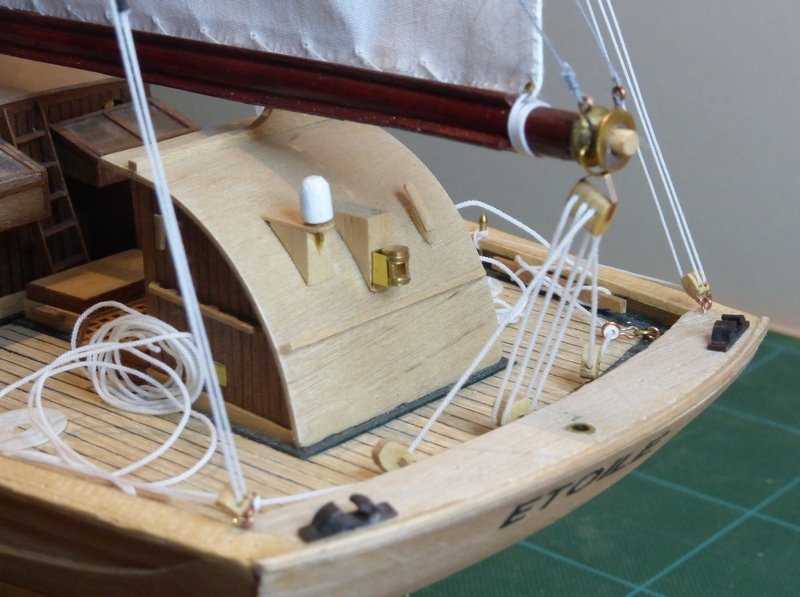
I am finished. What that means is that I have done all I am going to do. We all know that there is always something else that could be done and at some point a line must be drawn and that is it. In fact I finished a week ago. It has taken me a week to get around to taking a few close ups of what I have done since my last post. Once I have built a stand I will take some new pictures of the whole thing. Which is another thing that has delayed me. I thought I had a bit of wood I could use as the stand, but unfortunately when I found it, it was warped. I now need to find/purchase something else. Oh well, here are the pictures. The ships boat rigged on its davits. A top down view, in both this and the last picture you can see the spare anchor stowed forwardof thefore davit. The poop deck with railings binnacle, the ensign and my painting of the stern decoration. Not happy with the way the flag is hanging, will have another go at that. Again a shot from above, the compass face shows a bitbetter here. There is a little stick on top of the foremast which mounts a weather station and what I assume are navigation lights. I have not tried to represent the weather station. Where’s the aftermarket PE. That chimney/funnel thing. Some mooring rope; there was also some in an earlier picture. The anchors mounted and the spars for the ‘fortune’ sail stored on the fore shrouds (difficult to make out). A closer view showing how all the anchor chains are secured. That’s all for now. I will post again when I have built the stand and taken some pictures of the whole thing. By that time I should have decided what to make next, also I will reflect a bit on this build. Glenn

- 101 replies
-
- 5
-
-
- L Toile
- Billing Boats
- (and 1 more)
-
Thanks henry. I had not seen the tube cutting vice before. It looks very usefull, I have put it in my wishlist on Amazon. Now I need to wait for a family member to spot it and a special event. Unfortunatly my birthday was in January. Fathers day in the UK is June 17th (74 days to wait) I do not know how many tpi the blade I use is, its just the finest one I have. The other thing I do is push some solid stock down the middle, but I always feel that is such a waste. What can you do with lots of 1mm lengths of 1.6mm brass rod; the tubeing I have been useing riecently is 1.8mm o/d. glenn
- 196 replies
-
- 2
-
-
- plastic
- soleil royal
- (and 2 more)
-
Just to mention I make thimbles in a similar way using tubing with a 0.1mm wall. Care is required. I find I cannot open 1 side fully and then turn it over and try to do the other side, it just opens the first side more. Turning frequently is required. Also I get some cracking, but most of the time this can only bee seen using x10 magnification. How do you cut your 1mm lengths? I use a jewellers saw but with the wall thickness being only 0.1mm the teeth catch so I have to cut by drawing the blade backwards after starting the cut. Glenn
- 196 replies
-
- 2
-
-
- plastic
- soleil royal
- (and 2 more)
-
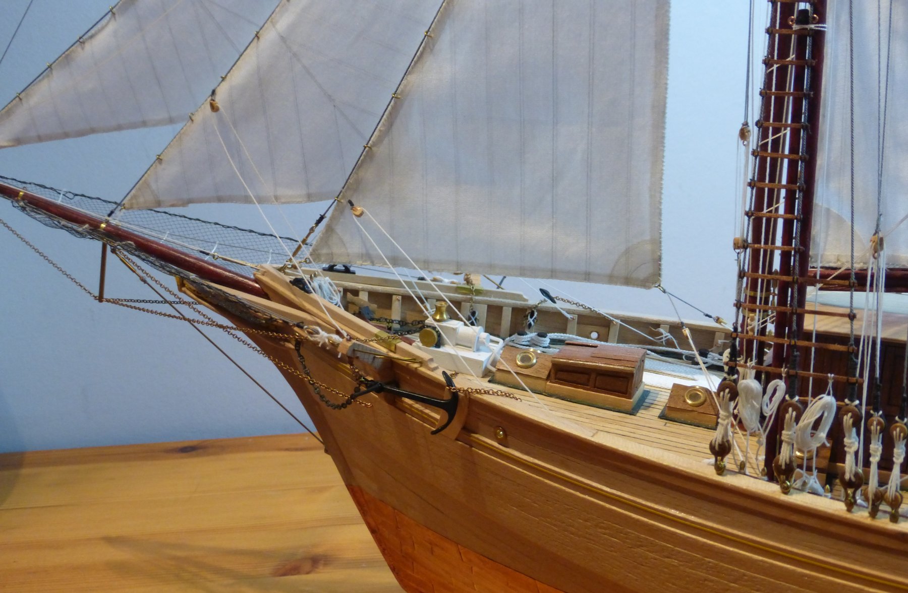
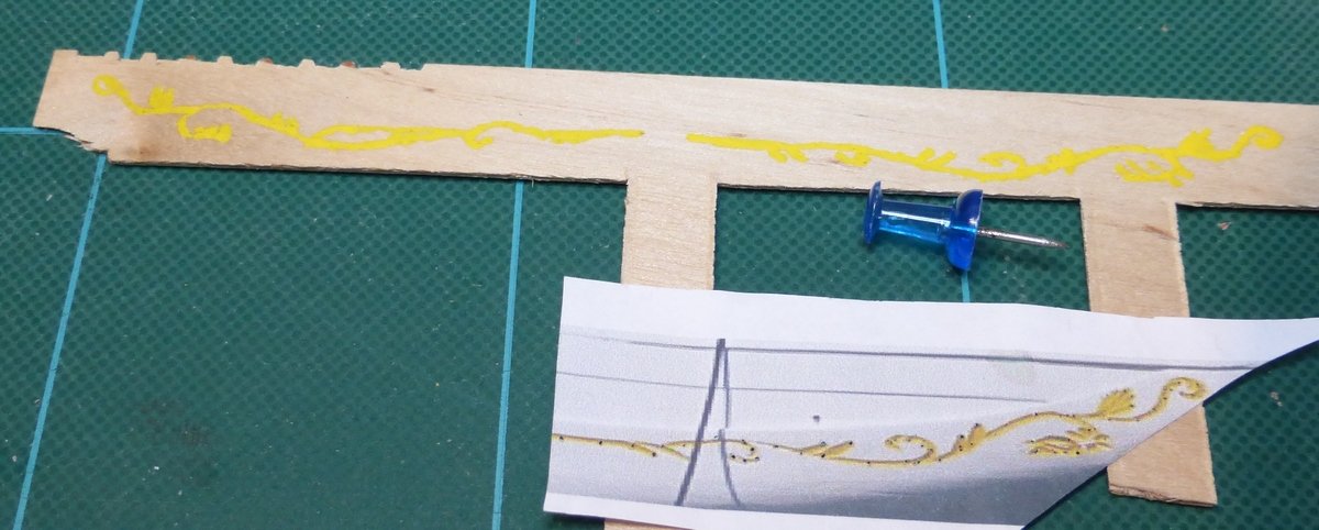
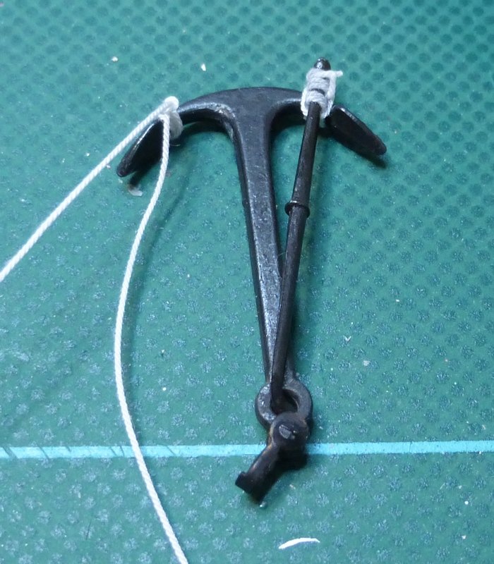
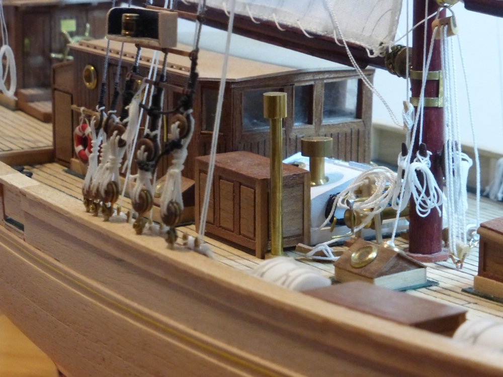
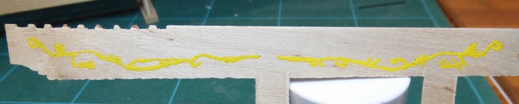
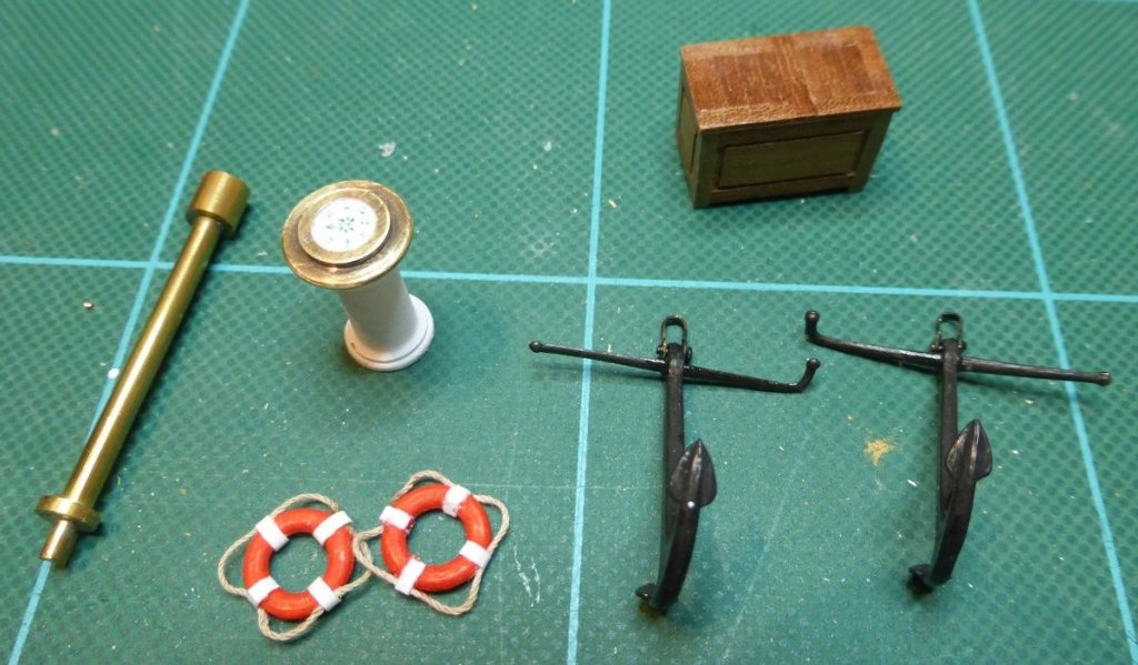
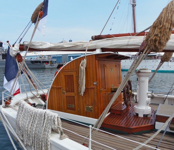
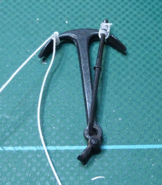
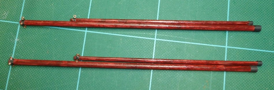
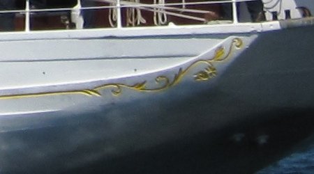
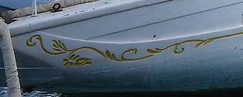
Juhu, thanks for the comment. As you say I much prefer the natural wood and use paint only when It is essential or I think for whatever reason it will enhance the model. Popeye, it was annoying but these things happen. Now the rigging is almost finished it is time to get some of those jobs I have been putting off done. The first of these is the decoration at the stern. This would have probably been easier to do before adding any masts or rigging, but it is painting so I use any excuse to put it off. In this case the excuse was it would get damaged and I would have to go over it. Seems fair to me. Indeed this is one of those times when I feel paint is required. This is a couple of shots of the stern decoration on the real thing. There are slight differences. Different times, who knows. First a practice. What I did was by trial and error printed out a view to the size required and then used a pin to transfer the image to some scrap material. Then I painted over the pin holes. I turned the image over and transferred the image, the other way, by using the first set of pin holes. This is a couple of views of the result. I got the one on the left wrong first time, luckily this was practice. This is 3 coats of paint. Pin holes are not visible. Guess it’s time to have a go for real. As well as This I have a bunch or other parts I can fit to the model now most of the rigging is done. The only rigging left is that that holds the ships boat on its davits. I assembled the anchors. Making shore one was right handed and one left handed, for port and starboard. The chest and that metal thing, which is referred to as a funnel in the plans, I had made some time ago. The lifebelts were supplied as part of the kit with a plastic rope. I cut off the rope and replaced it with some rigging cord. The other bit is the binnacle. I painted most of it white, leaving the top bare brass and printed a compass face for the top. It does not show too well in the picture, the compass face is about 6mm across. The ships binnacle actually looks like this. Billings representation is just a standard part and does not really represent the real thing, but I never intended to replace this. Then there is the spare anchor. This is mounted on the deck secured to the bulwarks, just forward of the davits. Looking at the picture I now realise I have left off some binding that secures the bar to the stock. Then I made the spars used for various sails at the ships bow; as shown in pictures in various previous posts. I have no idea how these are rigged when in use, but when not in use they are secured to the foremast shrouds, so that is where I will put them. The end is getting near, I do not envisage any real problems with what is left, but there are still a number of jobs to do before I will call it finished. There is also the issue of making a permanent stand, for which I will have to source some suitable wood. There is no chance of a display cabinet, I have nowhere to put the model as it is, let alone the extra space required for a display case. Thanks to everyone for looking in, Glenn

- 101 replies
-
- 4
-
-
- L Toile
- Billing Boats
- (and 1 more)
-
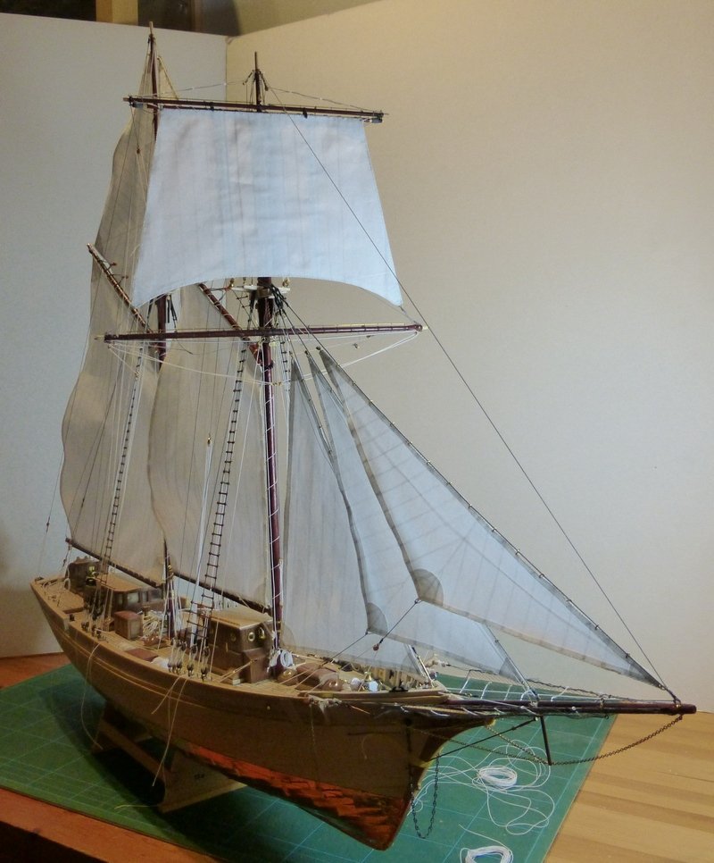
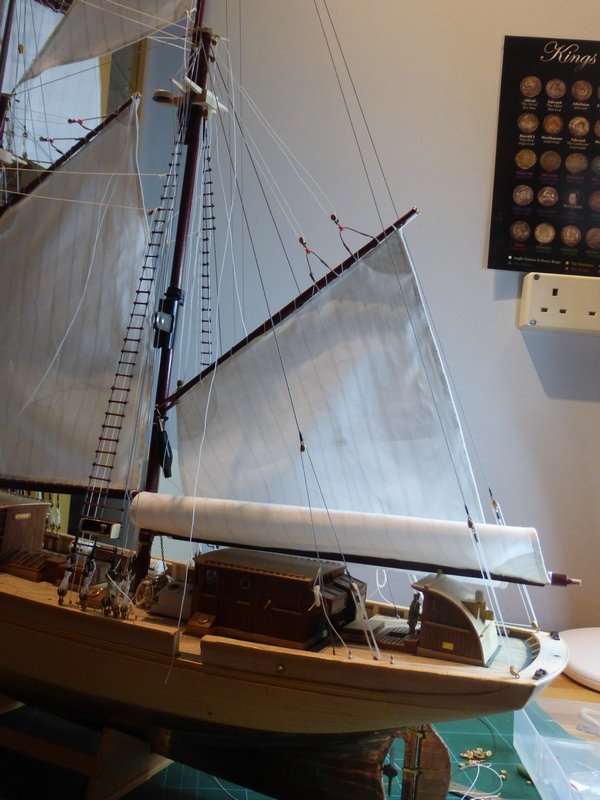
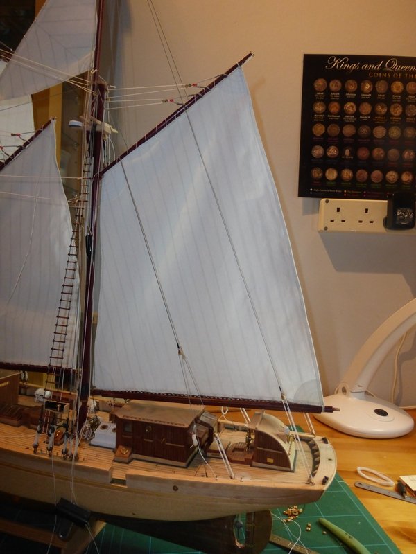
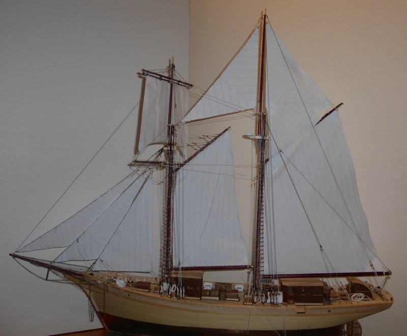
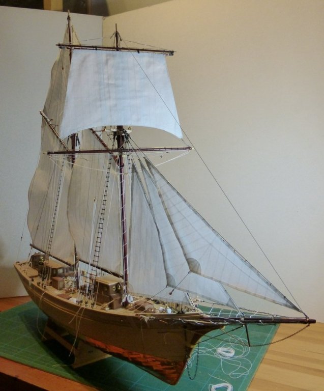
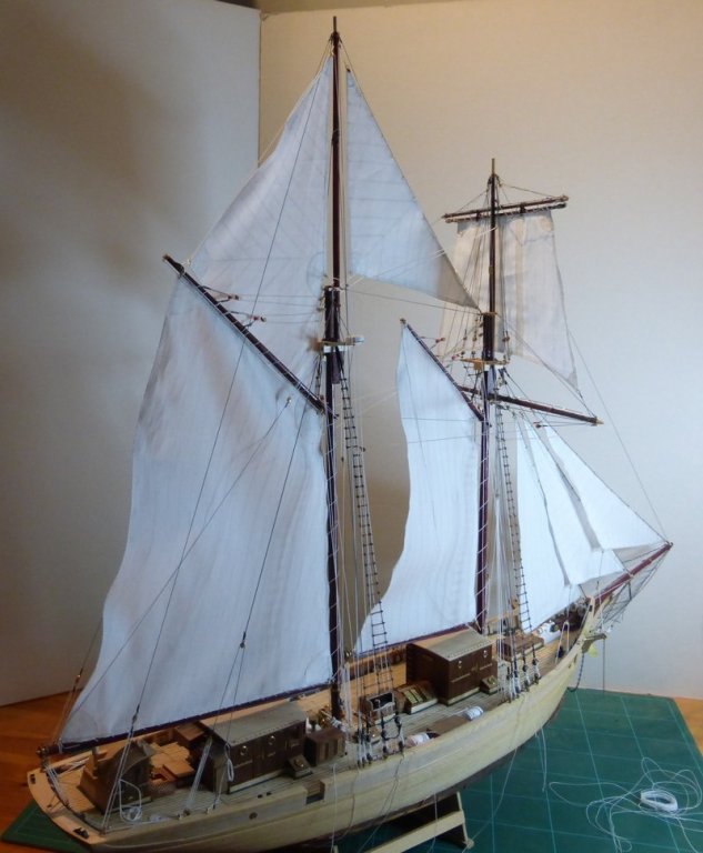
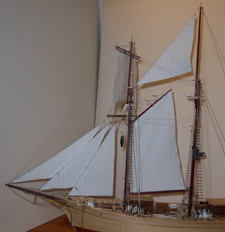
Again, thanks for the comment Popeye and also thanks for the likes and anyone for just looking in. This is just a quick update with a few photos as I have finished the sails, most of the rigging and taken a few pictures. All that is left of the rigging are a couple of flag halyards going to the end of the mainsail gaff and rope coils. In fact these pictures were taken 5 days ago and as for rope coils I am now on the last pin rack. After this all that is left is all those jobs I have been putting off. A lot of these are because it was sensible to do the rigging first, like the poop deck railings. Some because I had grand plans which will now not come to fruition, for instance making it so that the entry port gates are removable. These will now just be fitted in place closed. Some others because at the time I was not sure exactly what to do. The best example of this is the ships launch/Inflatable, which I started and have not finished. Recently I found a good top down view of this which has helped a lot in deciding what to do with this. I will also mention those hoops I took so much trouble with to put on the main mast for the main sail. As soon as I tried to clip them onto the mainsail they fell apart in my hands. The plastic had become brittle! Really annoying as at this stage it was not worth trying to fit something else. The pictures Thanks, Glenn

- 101 replies
-
- 6
-
-
- L Toile
- Billing Boats
- (and 1 more)
-
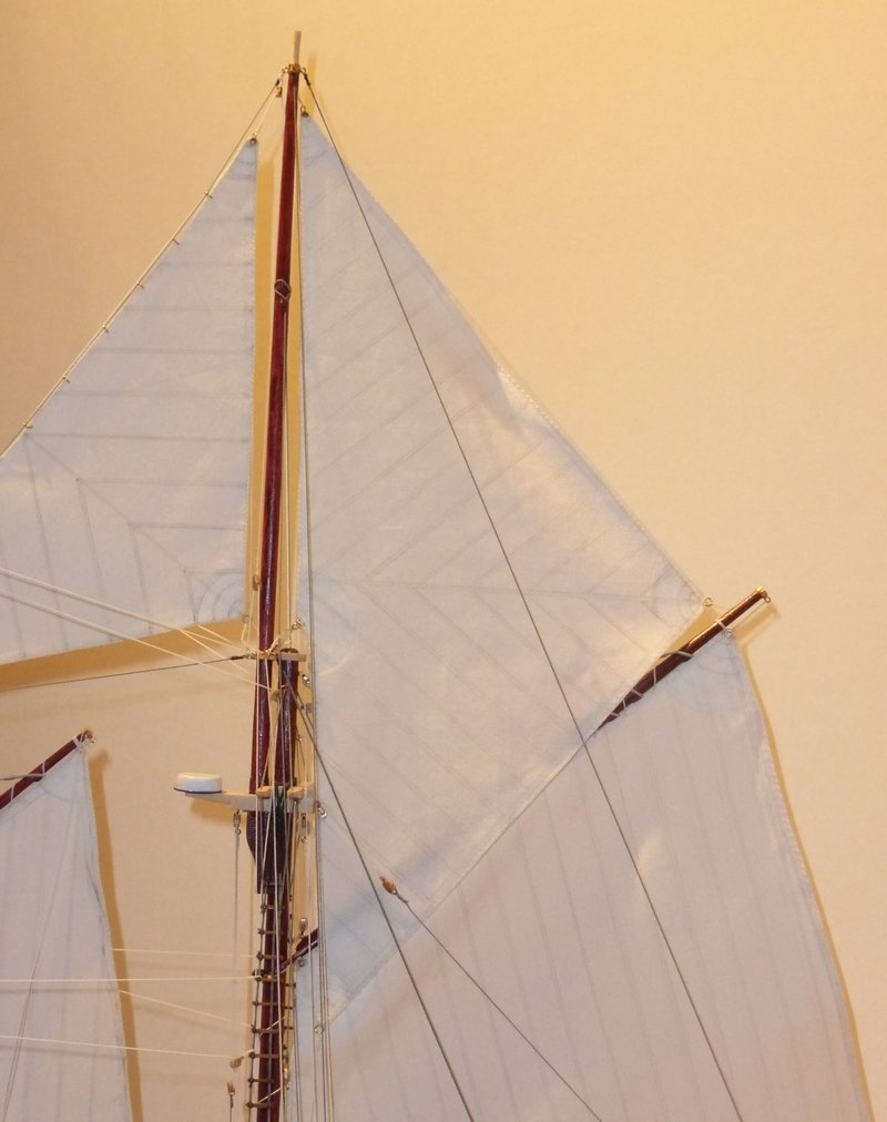
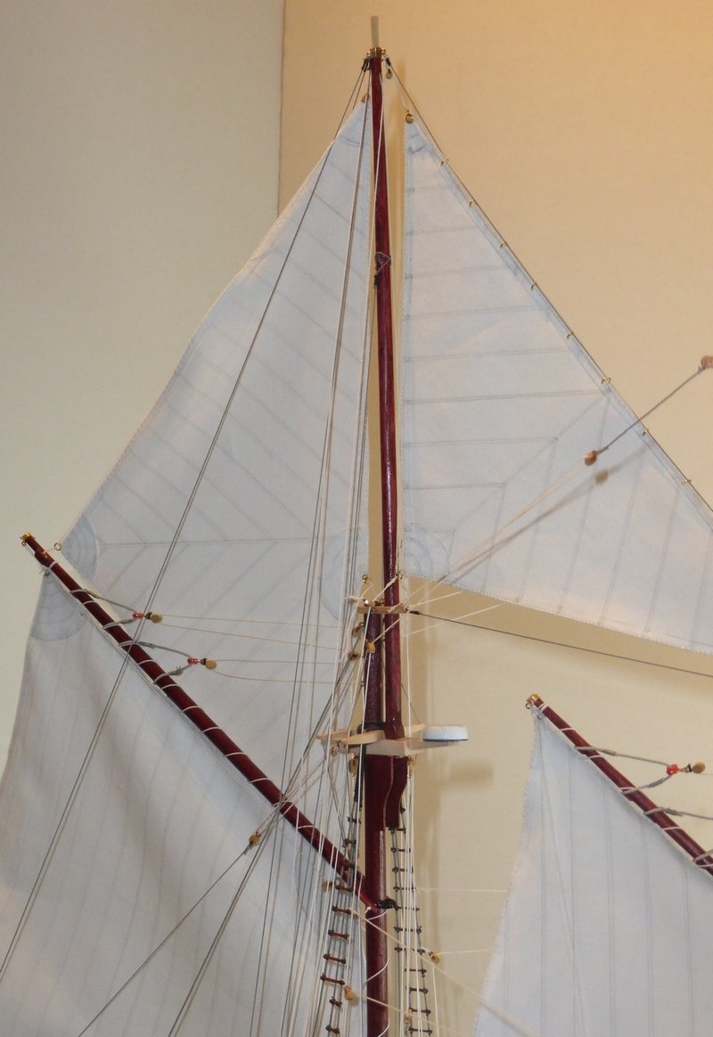
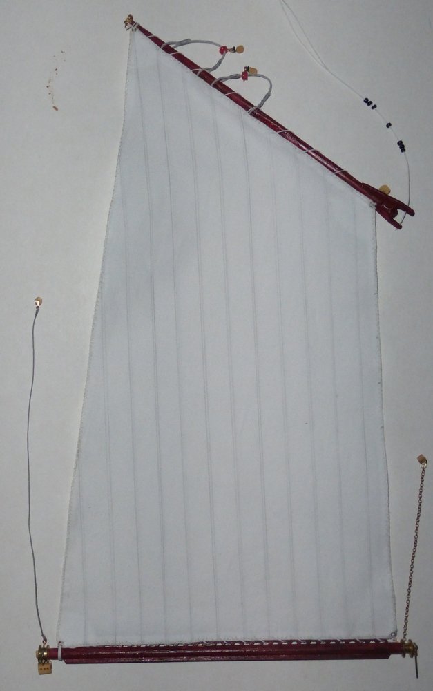
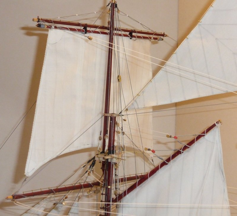
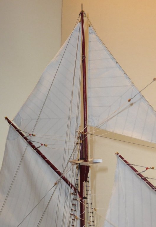
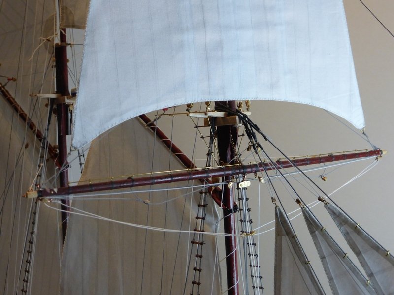
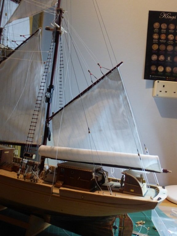
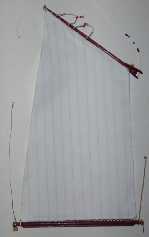
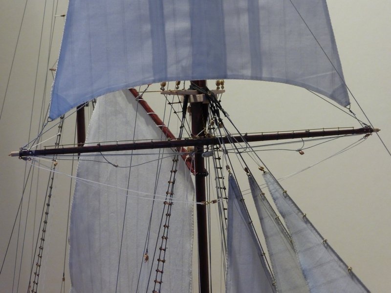
Thanks for the comment Popeye, also thanks for the likes and anyone for just looking in. I have been making steady progress since my last update. To start with I have completed the last 2 sails (mainsail and gaff topsail) and their associated boom and gaff. My hands are much relived that there is no more sowing and the ache/RSI is easing off. The last session was a bit of a nightmare, but I gritted my teeth and got it over with. I then lashed the mainsail to these and fitted this to the model. The goose neck was slotted into the fittings already attached to the mainmast, after which a ring was soldered in place to prevent it moving vertically. The boom was then slotted onto the pin protruding from the gooseneck. This is a fairly stiff fitting and I have not glued it so the boom can rotate a bit into the correct position. I then rigged the gaff throat and peak halyards and hoisted the mainsail. While making this I was able to correct some problems I had had with the foresail. The main one being the foresail was too far from the foremast. Looking at this, slightly fuzzy, picture, it is possible to see that the sail is close enough for the mast rings (resting on top of the gooseneck) to reach it, which was not the case for the foresail and I had to cut the rings off and use a line for the whole length of the sail. I should have the gaff topsail on today, then I have a lot of lines to belay and rope coils to attach (ugh). Glenn


- 101 replies
-
- 3
-
-
- L Toile
- Billing Boats
- (and 1 more)
-
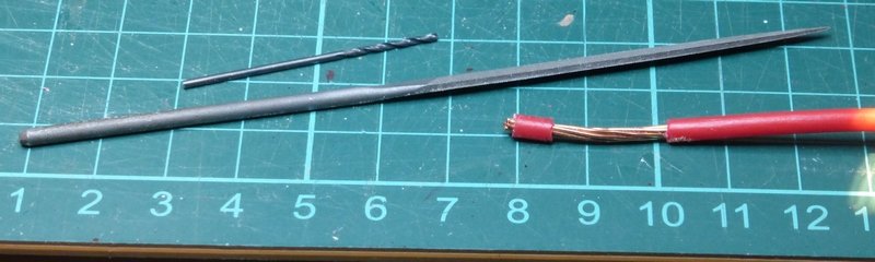
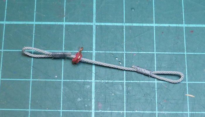
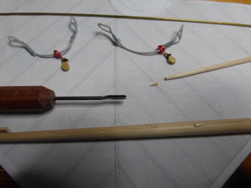
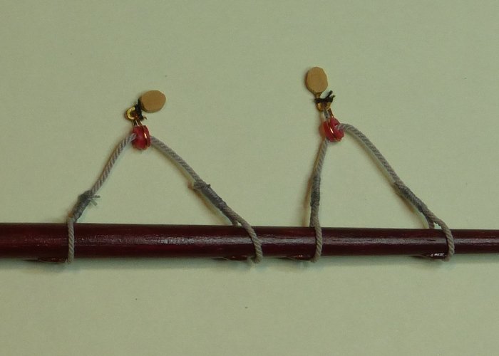
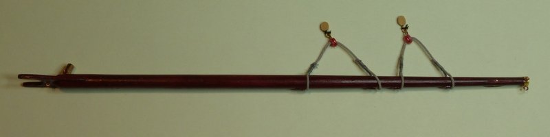
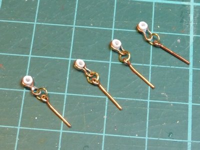
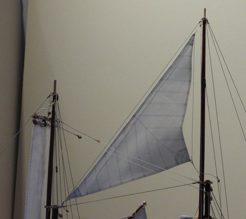
popeye, thanks for the complements. My heart did stop for about 5 seconds when I gave her the knock, but as there was no real damage I recovered quickly. Over the last few weeks I have come to the conclusion that doing rope coils is my least favourite bit of any build. I would even go as far as saying that I do not enjoy doing rope coils. There I have said it. So no rope coils on this update. I have been making the last two sails and some bits and pieces associated with them. First, the mainsail jib. This is what the rigging for the peak halyard looks like, it is the same as that for the foresail. I do not know why I did not make the required bits at the same time. Or maybe I did and have lost them. So starting off with some wire, I cut off a small length of the sleeve and then filed a groove all the way round. I did this using a new needle file I have purchased. It is a 12cm Vallorbe knife edge cut 4. I cannot express in words how wonderful this simple thing is. It is a joy to use. I could go on. I then used a craft knife to cut the ends off such that the grove was in the centre. The o/d of this sleeving is about 3mm. I then used some small pliers to fashion some copper wire to form the correct shape around this, with the help of some drills as formers. Then a quick dab of solder to join the ends, being careful not to melt the sleeving. The copper wire I used was supplied in the kit, no idea what for. It is thicker than the strands of the wire I got the sleeving from. This was then fitted to the middle of some rigging cord with loops formed at each end. Two of these were required. I also fitted single blocks with hooks to each. To stop these slipping along the jib there are some sticky out bits. Do not know what to call them. I had an idea and modified how I normally make these. I have a 1.5mm semi-circular gouge. Using this I made some cone shaped slots narrow at one end and 1.5mm across at the other, about 3mm long. I then got some cocktail sticks, sharpened the ends of them, then cut the ends off at the 1.5mm diameter point. I then glued these in the slots. The picture below shows the first one in place and one more ready to be glued. This worked very well and was easy to do. This is it stained and assembled. Another couple of pictures of the finished piece. The sheets for the foresail and mainsail have the arrangement where there is a triple block on the end on the boom and a double block on the deck. Then there are two lines that come down from the triple block through these sheaves and then to cleats on the deck. These are similar to the bits I had just made for the peak halyard and were made in the same way. The difference being these are slightly smaller. I started with some wire sleeving that was 2mm o/d. This time I made enough for both sails. At this point I had not rigged this line of the foresail. They are not all quite the same but it is not noticeable on the model. This shows the material cut out for the last 2 sails. I have drawn on seam lines but have not yet glued on reinforcement patches. I will be glad when the sails are finished as I am getting RSI from sowing the bolt ropes on by hand. However my stitching is much neater now than when I started. Though the bolt rope on the mainsail is about 75cm (30 inches) long and each stich is about 2mm. Glenn

- 101 replies
-
- 3
-
-
- L Toile
- Billing Boats
- (and 1 more)
-
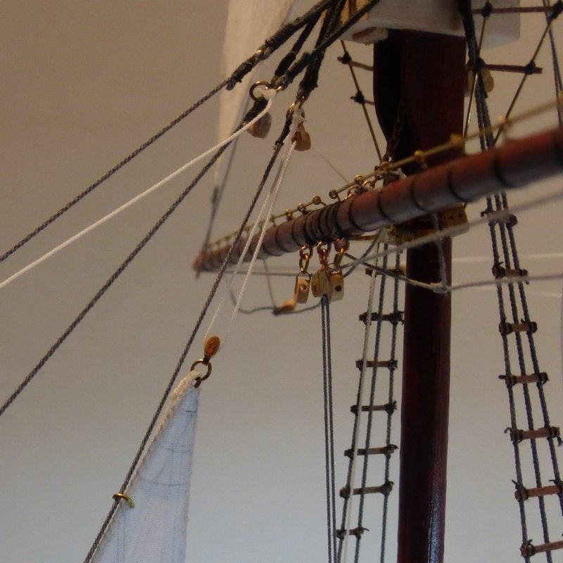
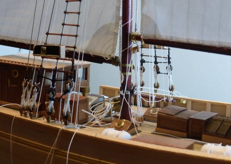
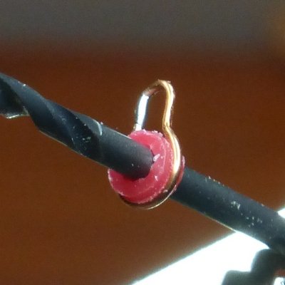
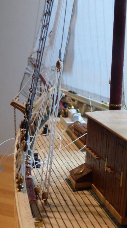
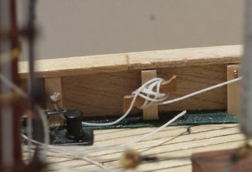
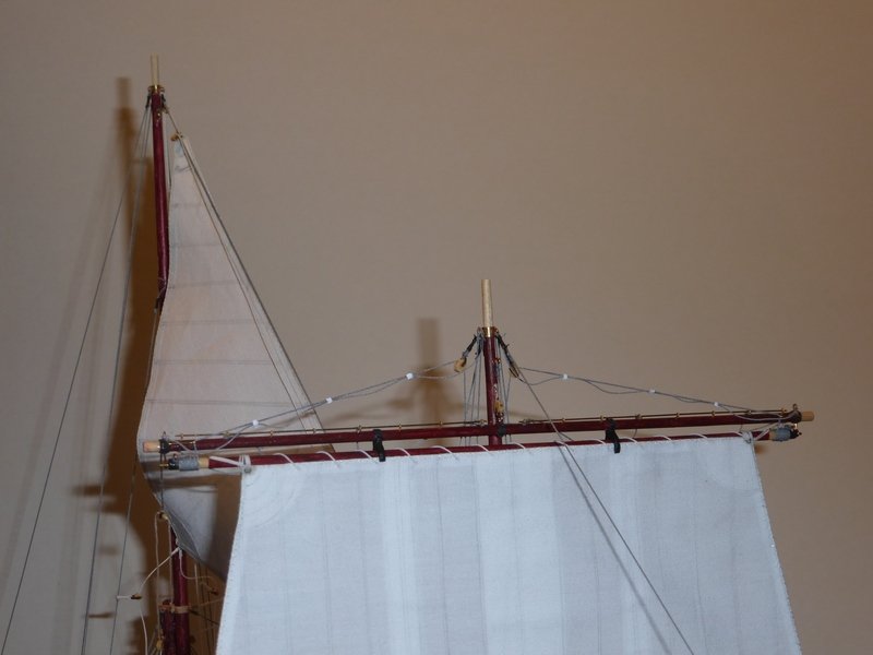
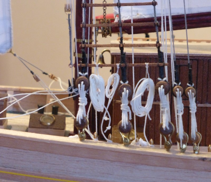
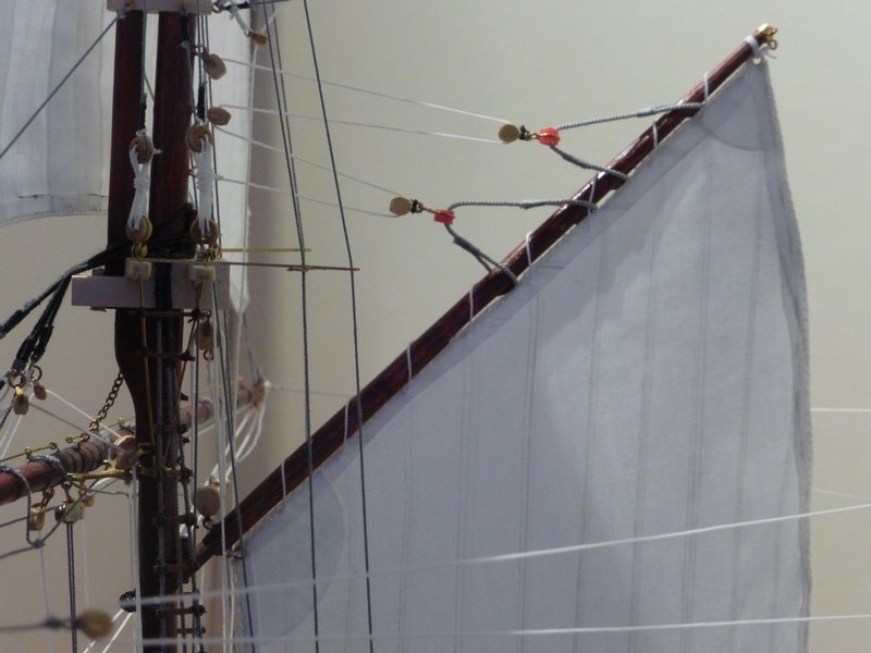
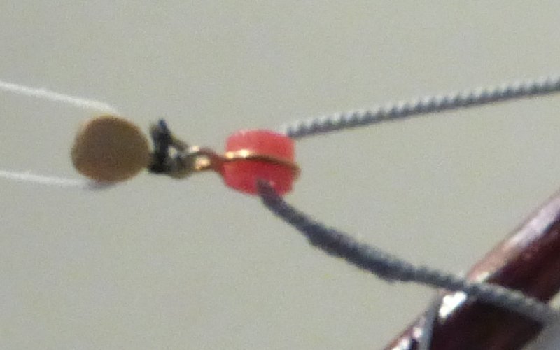
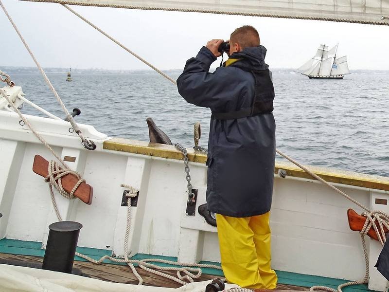
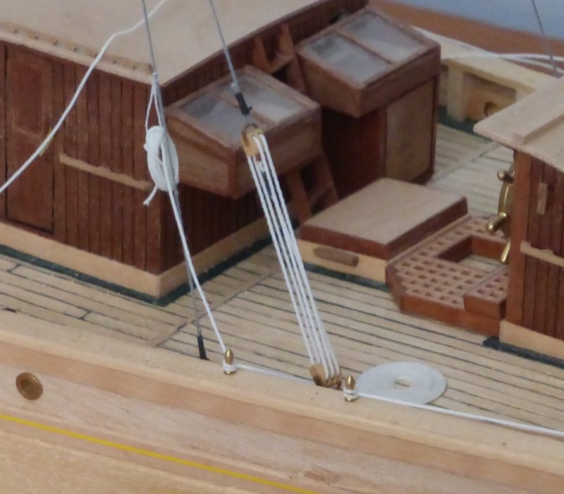
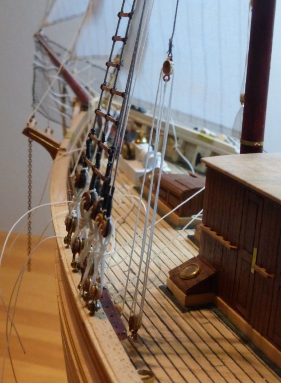
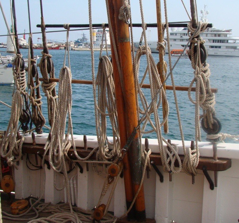
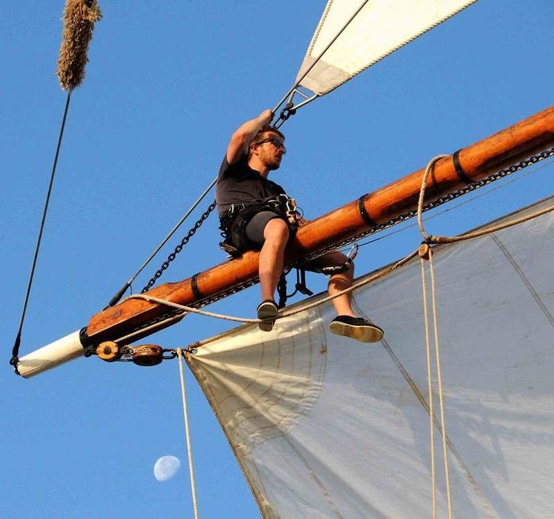
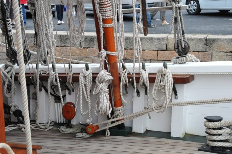
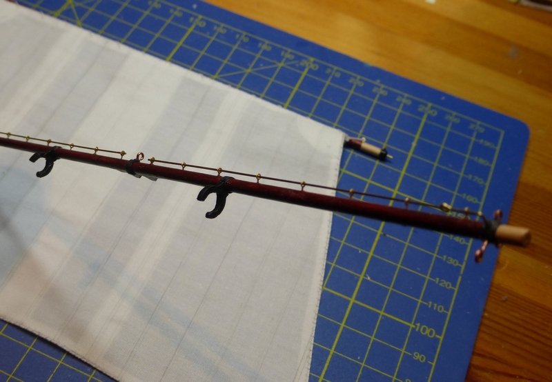
since my last update I have not made as much progress as I would have liked; lack of time. As can be seen in the following picture I have started rigging the foresail and the topmast staysail. Note the black crocodile clip hanging forward of the foremast, I will come back to that later. I assembled the foresail, the foresail boom and jib before adding them to the model. It was very easy to add this to the model. I just had to slot the pin on the boom into a couple of eye rings on the mast to make a swan neck and rig the jib throat and peak halyards. The pendant for the topping lift is rigged by a tackle to the main top the free end of which goes to a cleat on the mainmast. The chain for self-reefing mechanism goes via a set of tackle attached to the topmast crosstrees and down to a cleat on the foremast. The triple block for the sheet is matched to a double block on the deck with the two free ends going to two cleats, one on each side. I have rigged the topmast staysail, but only secured the lines that go to the foremast pin racks. The ones that go to the mainmast pin racks are still just hanging. Here I am having problems with the halyard. This passes through a block and down to a cleat near the deck on the mainmast. On the way down it rubs over everything in its path. I would have thought that if this was correct it would wear quickly. Conveniently both sets of plans show it coming through the block and then there is drawn an arrow and a number referencing the cleat. I have also spent some time putting on coils of rope. I have two methods for this. If it’s easy/accessible I leave enough line on the belay pin for the coil. Then I leave a short length and coil up the rest. I then use a crochet hook to reach through the coil, hook the short length, pull it through, give it a twist or two and loop it back over the belay pin. Then either a quick drop of CA or brush with dilute PVA, depending on how I feel. The other way is to leave a reasonable length of line and use a separate coil. Again I use the crochet hook and pull the line on the belay pin through the centre of the coil, give it a twist or two and loop it back over the belay pin. All the while holding onto the free end of the line which can be pulled to get the length of the loop correct. A quick drop of CA and snip off the excess line. For example the head sail downhauls. Two of these were done using the easy method, but the 3rd would just not go, so I used a separate coil. Just noticed the flap is up on one of the chain stoppers. A couple of easy ones, one suspended and one Flemish coil. Not all lines end in a coil, for example a sheet for the inner jib: This is a sheet for the outer jib. This is what I was trying to emulate above. Could not get the line to lie the same way. Every time I look at this picture I think that is a dolphin poking its nose over the rail. Some rope coils hang like this. This is very common in pictures of the real thing. Looking, I need to have another go at this, some of those coils are a bit wonky. This shows the tackle for the topsail yard tie, the line of which passes through a block on the deck before being fixed to a pin. The fully rigged topsail yard: at last. Those little white things were a bit fiddly, they are just little coils of paper. The lines that are not tight are, I think, the lifts. They only come into play when the yard is dropped to its lowest possible position. Other than that they just hang from the chains of the self reefing mechanism. The little paper bits are spaced evenly along the lifts and can move along the chains. A latter picture shows this on the real thing. This shows the main yard. Remember that crocodile clip. That was clipped to where the blocks of the ‘Fortune’ sail (which I am not putting on the model) halyards are coupled together in the middle. The crocodile clip gave it a bit of weight while some dilute PVA I had brushed onto the lines set. Now I have removed the clip they are holding the shape I wanted. The foresail jib, showing the rigging of the throat and peak halyards. The red bits are sleeving from electrical cable. It was fairly hard stuff and I could file a groove round the middle for a brass fitting to match the hook on the block. Sorry the blow up is a bit fuzzy. Tied a constrictor knot round the hook, added a frapping turn round the centre, tied it off with an overhand knot and a tiny touch of CA to finish. One last picture, this time of the real thing. Thought I had better point that out. This picture is my guide for this part of the rigging. note the little white bits (they look a lot darker in this picture). I think I have just spent more time composing this update than I have spent working on the ship since the last update. Something to think about. Glenn
- 101 replies
-
- 6
-
-
- L Toile
- Billing Boats
- (and 1 more)
-
The Charles G Davis books are filled with information for those of us who have never been to sea in a wooden sailing ship. An invaluable resource I would not hesitate to recommend. Glenn
-
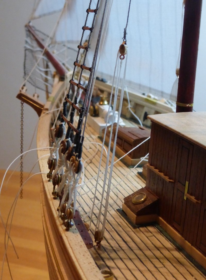
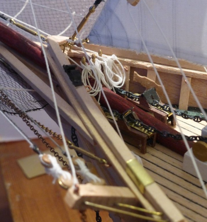
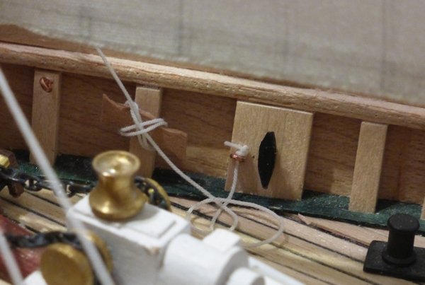
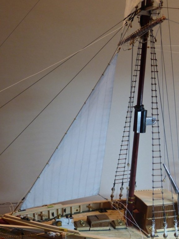
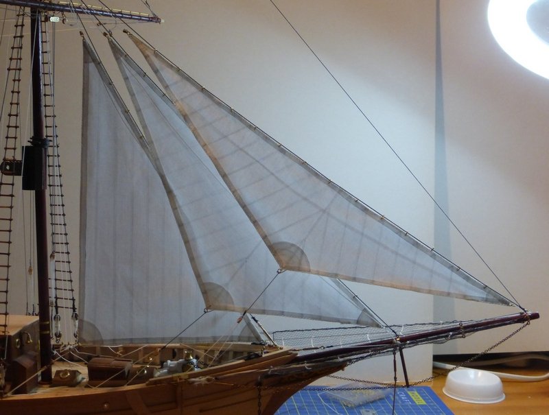
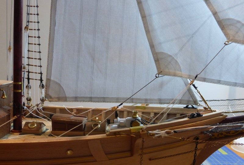
Moving along slowly at the moment as I am being kept busy with lots of small improvements to the house. Learnt a new skills - laying vinyl. I started the head sails with the fore staysail. The most difficult part of this was putting on all the rings along the fore stay. Not sure about what to do with the 2nd sheet, the one that is not in tension; at present I have left it hanging. Any knowledgeable people out there that can let me know what should be done with this. The halyard goes through 3 blocks before it goes down to the belay pin, these keep it clear of the yard. The last of these is attached to the futtock shrouds. The yard is obscuring the relevant one of these on the starboard side though the one on the port side can be seen, it is the double block just below the yard on the right. This one will take the halyards from both the inner and outer jibs. Also noticed that the jack stays are not as straight as they once were. This happened when trying to mount the spar after the part of the parrel attached to the main yard broke. This was due to the part from Billings not being made very well. A slot had been cut off centre leaving one side very thin. When I inserted the part of the parrel attached to the spar the thin bit just fell off. While it cannot be easily seen, it means the yard has ended up tilted slightly forward. But to do anything about it at this stage of the build would be too much work. Finally all three head sails are in place. Those of you who are paying attention may have noticed the angle of the bobstay. I gave it an almighty knock when reaching quickly under the bowsprit, forgetting it was there. This broke it off the cutwater. On reflection, I think I was quite lucky it broke otherwise the whole model would have ended up on the floor with probably a lot more damage. There are a lot of loose ends at present. I need to cut these off and add rope coils. The reason I have not yet is because a lot of these are coiled in the shrouds, as shown here. I still need to finish rigging the fore topsail. I found I did not have a piece of grey rigging cord left that was long enough. I have plenty of pieces but all slightly too short. I am using grey to represent steel cable and chain. I have been unable to source any real chain small enough to go through the holes in the blocks. Apart from making more rigging cord I also need to make the final 3 sails and some more blocks before doing any work on the actual model. This will not present any problems as it is just repeating processes that I am well practiced in, though the size of the mainsail will make that more difficult. One final picture from the other side. Glenn

- 101 replies
-
- 5
-
-
- L Toile
- Billing Boats
- (and 1 more)
-
I think this is a really nice looking model. The kit looks very well thought out. I cannot believe how quickly you have completed it. Glenn
-
When you state that you have researched the ship you mention the McGregor plans. Did you view or obtain copies from the Brunel collection? The reason I ask is that I was given this kit for Christmas and knowing about its short comings I intend to try and view these and possibly obtain copies but have not yet been in touch to find out how to go about this. Glenn
-
I especially like that bit with a lifebelt on one side and what looks like a winch on the other. It looks properly riveted together. Glenn
-
I trust that is olive oil and not acrylic. Glenn
- 378 replies
-
- 5
-
-
- t78 norden
- billing boats
- (and 1 more)
-
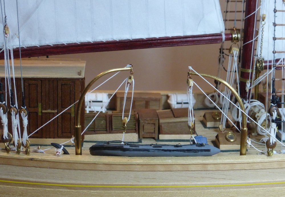
Popeye, I know what you mean, but it is so difficult to translate the text that came with the plans from the Musees de la Marine, which is in French. The word they use for these is 'Bossoir', which I think translates to 'davit'. For the lifeboat davits they use 'Pistolet' which I also think translates to 'davit'. The translation of Boom into French is either Bome, Gui or Guy (Bome seems to be reserved for the main sail boom) and nothing like these is used in that bit of text. So I have been mentally thinking of these as davits. I guess French maritime speak is as confusing as English (or American) maritime speak. Please excuse my lack of accents over some letters, do not how to do that, or if it is even possible here. Glenn
-
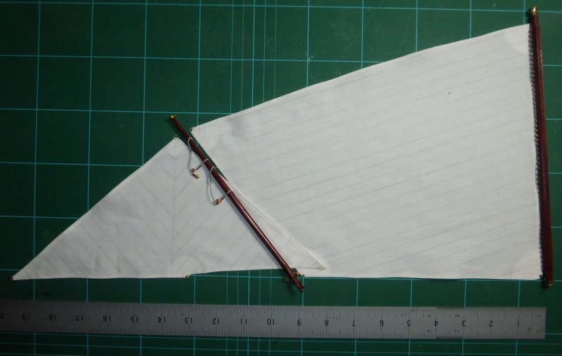
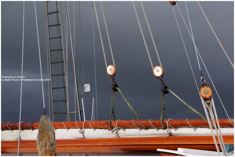
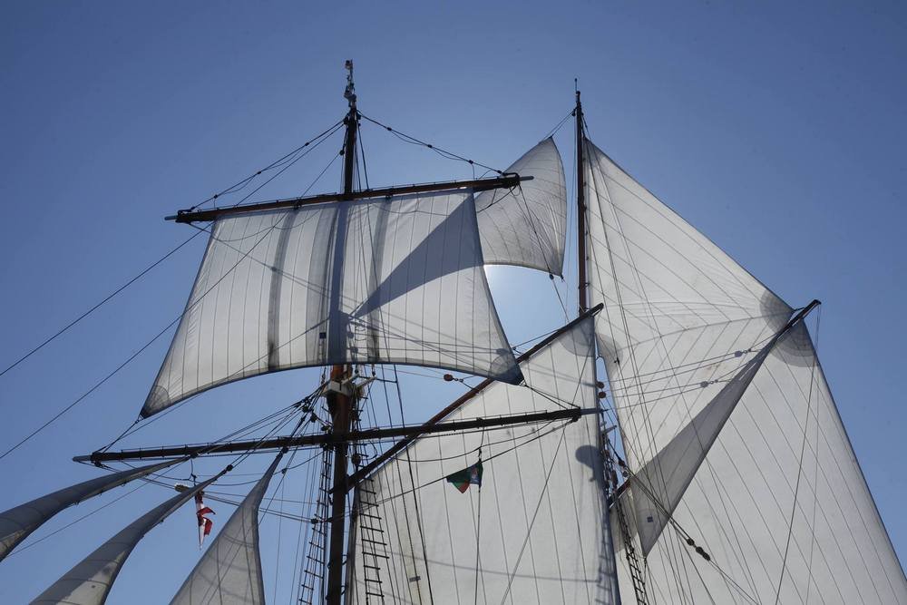
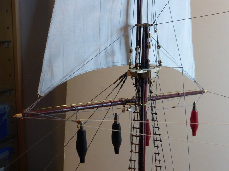
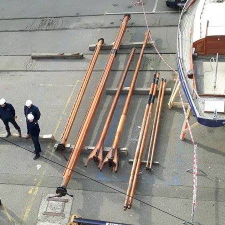
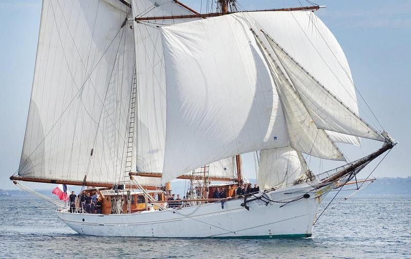
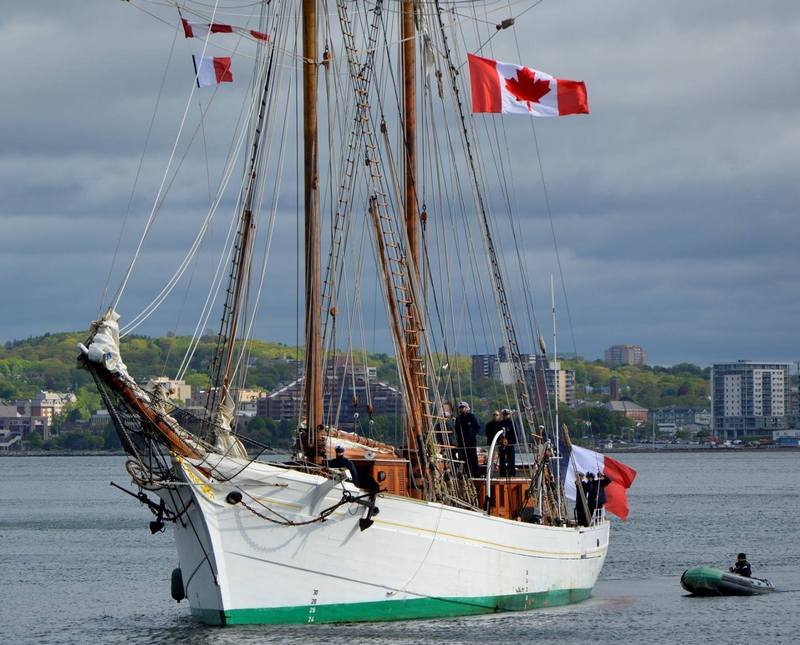
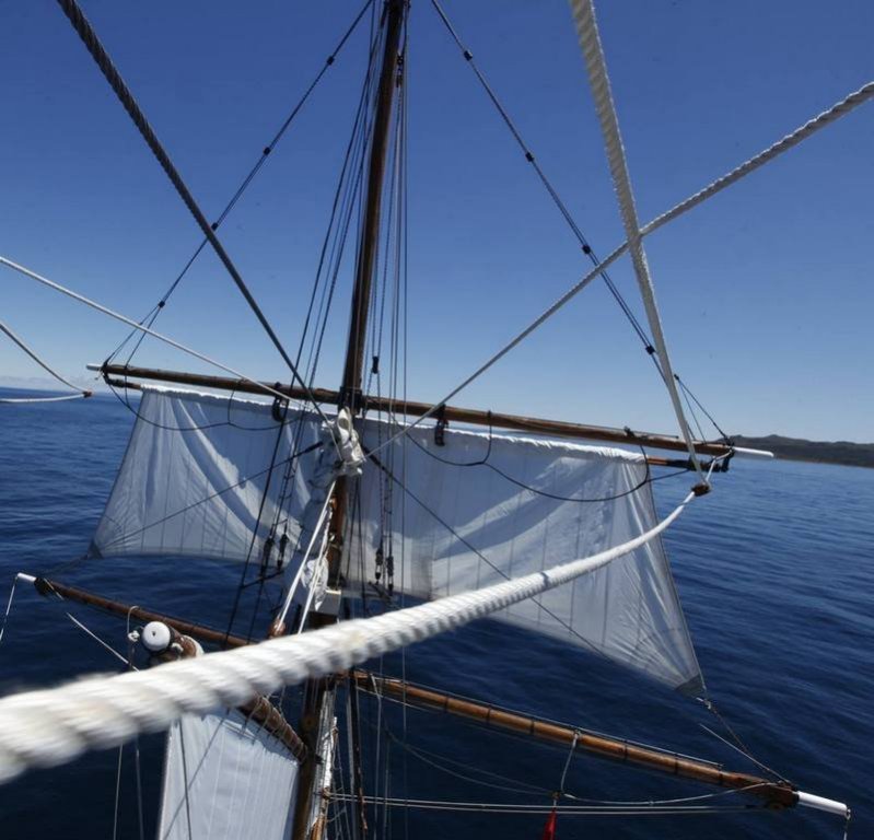
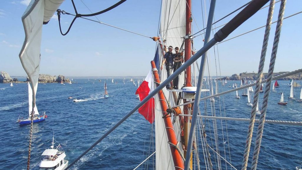
Finally the first sail is in place. I have not quite finished rigging it yet and once I have I will need to adjust things to try and make it look more natural. I think there was more work involved in this one sail than there will be for any of the others, at least I hope so. The self-reefing aspect also means the rigging is more extensive. The next picture was taken slightly earlier. I have hung some crocodile clips on the foot rope and brushed on some dilute PVA, the intention being that when it dries it will hold its shape and look more realistic. While doing this work I discovered that I had some of the standing rigging wrong. I had both pairs of backstays coming from the topmast. But I became curious about some unused eye pins on the cap. Looking at some pictures it appears that this is now where the first pair of backstays should be attached. Another difference from the drawings; the other difference being the spreaders for the backstays coming from the topmast. Looking at the first picture, the hang is a lot better than before, but I am not sure about realistic, though looking at the picture below the foot ropes do not loo as if they are rigged in the normal way. Next it will be the 3 head sales, which I have already made. To mount these I have to rig the halyards and put some blocks on the bowsprit to redirect the down hauls. So this should not take too long. Similarly I have made everything for the topmast staysail and can rig that easily once I have rigged the foresail which I still need to make, though I have already made the boom and jib for this as shown previously. Even though I feel I am getting near to the end, research still continues. One thing I have not done anything about yet are the davits used when the 'Fortune' sail is set. Not sure whet the correct translation is for this. But I refer to the large square sail shown in the picture below. The literal translation is 'Jury rig' so perhaps it is just that. Note the davits. There are also a shorter pair used when different sails are set instead of the fore staysail. The problem is I have no idea how long these are. These are not on any of the plans, even though they are mentioned in the text that came with the plans from the Meuseum de France. I have just found the following picture on the Etoile facebook site. It appears it has recently gone in for a refit and there are a series of pictures showing the spars and masts being dismantled. From this picture I should be able to estimate the lengths of the davits, shown to the right of the jibs, well enough to make decent representations of them. I intend to mount them in their 'stowed' position, on the foremast shrouds. Not easy to find a good picture of this, but: Glenn
- 101 replies
-
- 7
-
-
- L Toile
- Billing Boats
- (and 1 more)
-
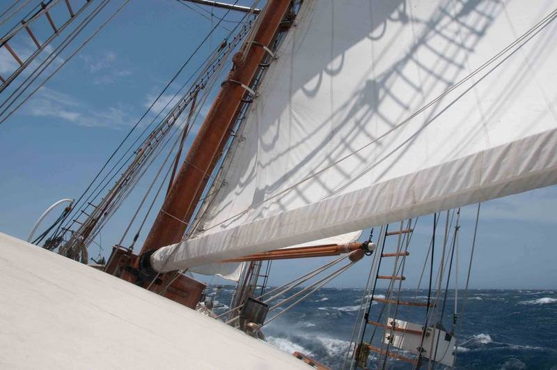
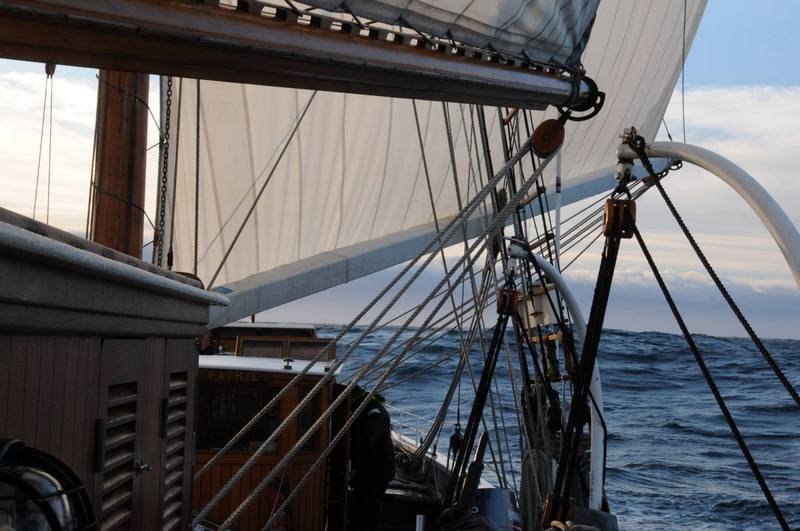
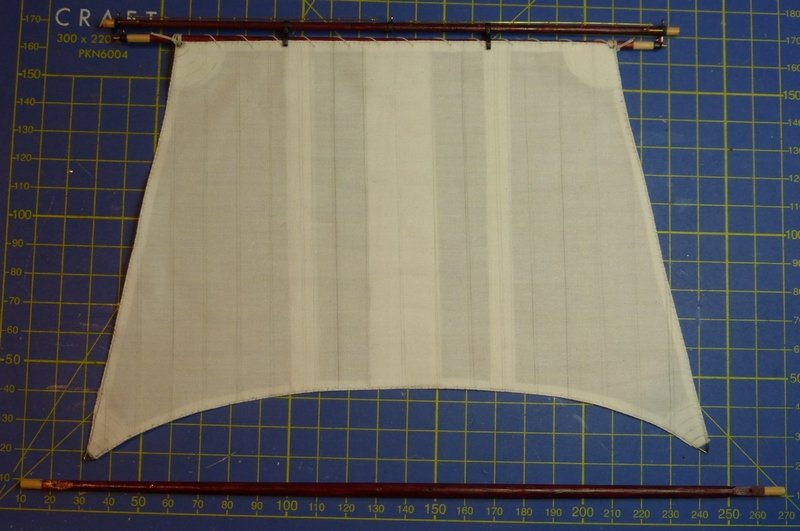
Popeye - No reef lines, sails are self reefing. To shorten the sails they are wound round a rolling spar. Take a look at these pictures. These first 2 show the mainsail shortened. It is wound round the boom and the jib is lowered. This picture shows the fore topsail. Part of it is wound round a rolling spar suspended beneath the topsail yard. The halyards are let out as the line that rotates the spar is taken in. I suppose this could be called the downhaul as I have seen no other name for it. You can see in this picture how low the topsail yard is. I was pleased with the way the block turned out. Just fitted the topsail yard braces. I have just got some thin CA which I used. Previously I have only used medium but thought it did not flow well enough over the rigging cord. The thin certainly flows better, but it is a lot more difficult to control and place. Either I do not get enough to the joint or I flood it. Bit of a learning curve here. Think I need to find the right tool, for medium CA I just use a needle, but that does not seem to work with the thin stuff. Glenn
- 101 replies
-
- 3
-
-
- L Toile
- Billing Boats
- (and 1 more)
-
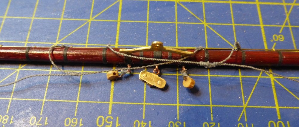
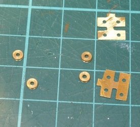
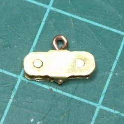
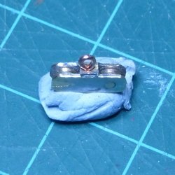
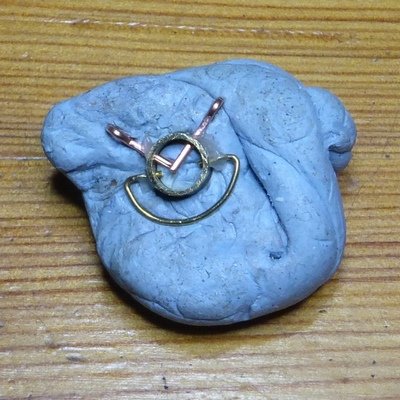
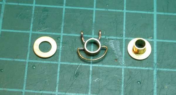
Thanks Popeye, I am pleased with how this is working out. A lot more detail than in the kit and a lot more work. Still some to do. I am working on trying to fit the first sail, the fore top sail. I have now finished the fore yard. One item that was required for this was a block mounted under the centre of the yard. You can see where it is in this picture, but it does not show it very well. This is the best picture I have of this. You can see the chains coming in from the side and then going down, these are the sheets. I am having to assume that whatever this is, it something like this one which is used to control the lines that reef the sail. On the drawings it is shown as a dashed square. I have some 3mm sheaves and I cut some pieces from 0.4mm brass sheet, with 1mm holes drilled for a couple of axles. This was done on the Proxxon MF70, leaving some tags which were sawn through after with a jewellers saw. This was then folded up with1mm brass rod as the axles, then soldered together and cleaned up. After that I drilled a small hole through the 2 bits that hold the two side plates apart and soldered in an eyebolt. As I broke one of the two shown while folding it, I still need to make a second, which will be the same except the eyebolt is not required. The completed fore yard is shown in the following two pictures. The blocks on the foot ropes are for sail halyards, as shown in the first picture above. I am using grey rigging cord as this is all wire cable. I now need to put the brace pendants and foot ropes on the topsail yard. I think it will also be easier to rig the sheets and the ropes that reef the sail off the model. As I was doing some metalwork, I made an assembly required for the main boom. Similar to the one made for the foresail boom. The first picture shows it ready for soldering. If you look carefully you will see some flux on the joints. The parts are held in place by blu-tack. The second picture shows the part soldered and cleaned up with the other 2 parts of the assembly. The middle bit goes over the bit on the right, then the washer is pushed over the end and soldered in place. I forgot to take a picture of this, will take one for the next update. That's where I am now. I hope to find time to mount the fore topsail in the next few days. Though it will probably take slightly longer to complete all the rigging required to operate the self reefing mechanism. Glenn
- 101 replies
-
- 6
-
-
- L Toile
- Billing Boats
- (and 1 more)
-
Good work, very neat.
-
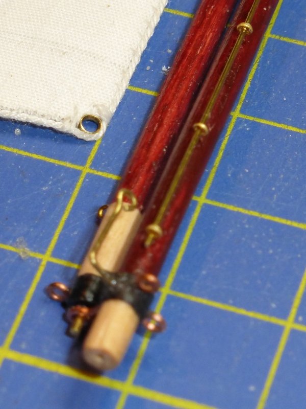
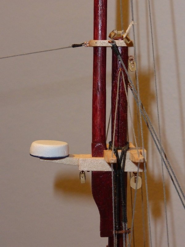
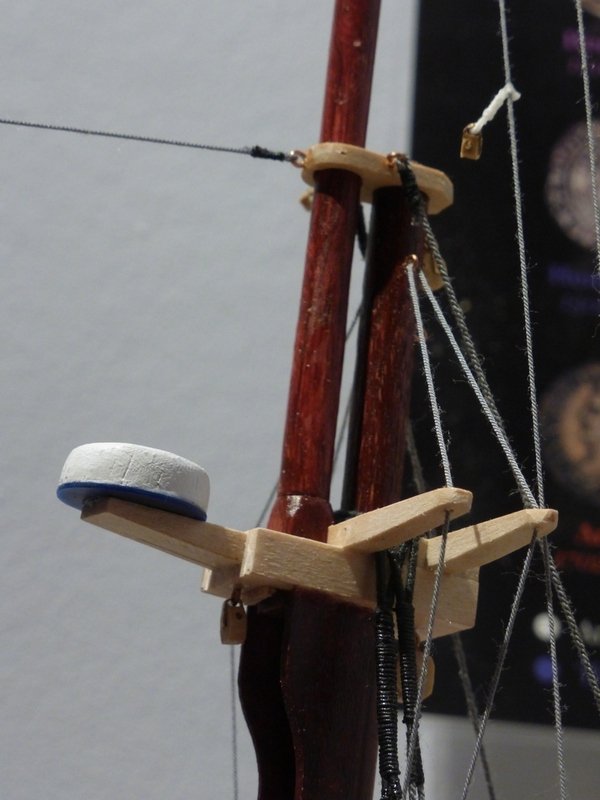
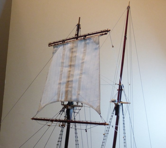
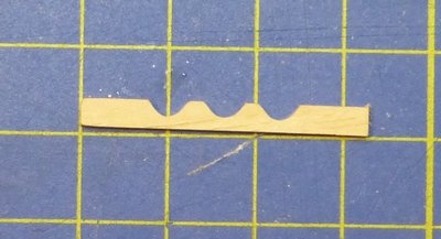
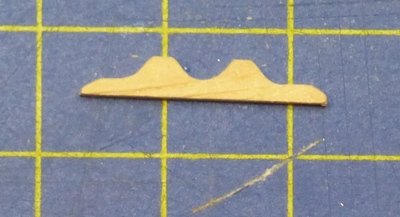
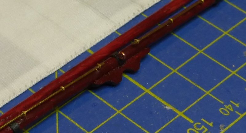
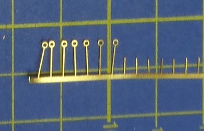
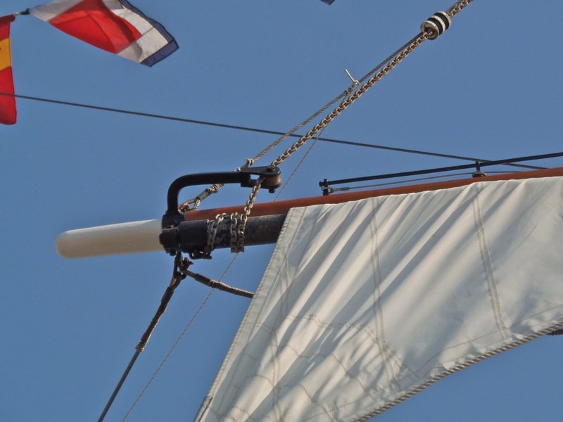
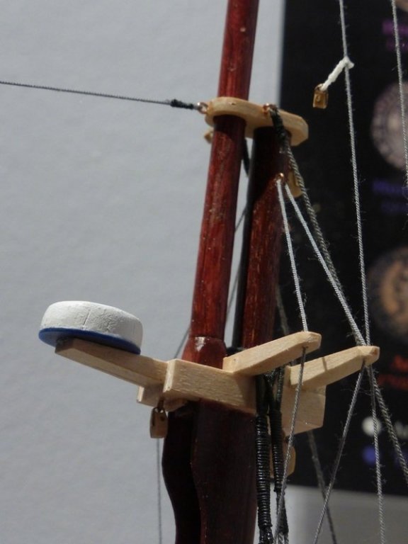
It’s been some time since my last update, I was busy preparing for relatives coming round over Christmas. This mainly involved sprucing up the bathroom (orders from the Admiral). A job that was meant to take 2 days but eventually took 10 days after some rotten wood was found and needed replacing. Full size tools were dusted off. Still bathroom is sparkling now. What time I have had on the model has mainly been spent building the fore topsail yard and making the fore topsail. Making the fore topsail was just a matter of repeating what are now tried and proven methods used on the other sails, the only difference being that this is a square sail and is bent to the yard with spiral lacing. The fore topsail yard was another matter altogether as a self-reefing mechanism is employed. Basically this is 2 yards. The topsail yard that is fixed which supports a rolling spar which rotates to wind in the sail. What is supplied in the kit is very elementary and does not attempt to represent the self-reefing mechanism. Also there is no parrel, the only attachment for the yard being a tie passed over a sheave in the topmast. So it was required to scratch build the parrel and somehow represent the self-reefing mechanism. First thing to do was to make some wooden cleats for the parrel. Starting with some 3mm x 1.5mm boxwood I filled 3 semi circles with radius 2mm: I then removed the excess material at each end, cut them to length and shaped the ends. I then glued and pinned this to the yard where a band had already been placed. This was made from black paper. Later I will add a half hoop, made from brass, which will attach to the back and go round the fore top mast. This will be fixed with a couple of brass pins. I then added some further bands made from black paper to represent the iron bands and eyebolts to attach a block for the tie and other rigging. Finally I added some small etched brass eyebolts to take the jack stay, to which the foot rope is attached. I had to wait some time for these etched brass eyebolts to arrive from Caldercraft, time of year, but they were well worth the wait. Made from 0.3mm brass with a 0.7mm eye. Here are a couple of pictures of the ends of the yard. This is what I am attempting to replicate. The next stage was to fix the sail to the spar then finish assembly. This picture shows the sail bent to the rolling spar and the rollers attached to the topsail yard. And with the finished item. I now need to finish the fore yard and add some rigging (foot rope and pendants) before fitting this to the model. One mall task I have completed is the Radome. The white top bit is turned from some unidentified wood I had lying around and the bottom blue bit is some 20 thou plastic sheet I purchased when I used to scratch build model AFVs in my teens. I knew it would come in handy one day. The finish on the wood is not as smooth and composite material like as I would have wished. I include this picture as it not only shows the Radome, it also shows the brace pendants and runners for the topsail yard (top left) and for the fore yard, bottom centre going to the first shroud on the main mast. That's about where I am now and where I was a couple of weeks ago. hopefully I will find some time shortly. Glenn


- 101 replies
-
- 6
-
-
- L Toile
- Billing Boats
- (and 1 more)
-
Just pulled my kit off the shelf; I have not looked at it for18 months while building the Etoile. I have just started the first planking. The bottoms of your gun ports do look a bit high. I bought a pack of 2 carronade kits to see if I wanted to use them or not. It has the advantage of plans to let you know how the barrel is meant to be mounted. These do not have that Y shaped bit of metal that attaches the carriage to the sill. Instead the carriage is slightly longer and attaches, via a pin, to a bit of wood on the deck. I suggest instead of attaching these to the sill you move them back a couple mm and fit them to the deck. See pictures towards the end of the HMS Sophie build log. May have to put in some padding to keep the front up. The bed of the carriage should be fairly level otherwise it affects the dynamics as the gun recoils. Also Pulling the gun out up that slope in your picture would break the gun crews backs. Doubt anyone would notice the difference unless they were a Navy historian. I agree its a very expensive option and, now I have seen them, why I will probably stick with the white metal pieces. Though they need some neatening up. Make some eyelets out of some spare brass rod supplied in the kit. Not sure what the sizes are in the kit, but their should be one with a fairly good fit in that hole. Or find some single strand copper wire, remove the insulation, and use that. Copper is easier to bend. Nothing like a bit of improvisation. Glenn
-
In your first picture the carriage for the carronade is angled up towards the gun port. I cannot see what you have done wrong in this picture but it should be roughly parallel with the deck. The hole in the bottom of the brass carronade in for an eyebolt (supplied if you buy the kit with the carriage). Once fitted it should mount on the carriages supplied in the kit in the same way as the white metal ones. Hope that explanation is understandable and of help. Glenn
-
Max, Excellent. Personally I think you have used just the right amount of paint to highlight some features, like the doors, and make the decoration stand out. No way it looks like a toy. Glenn
-
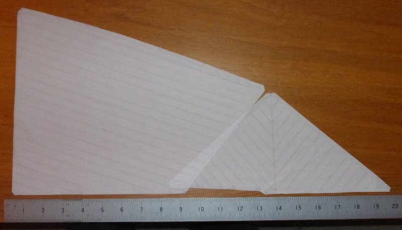
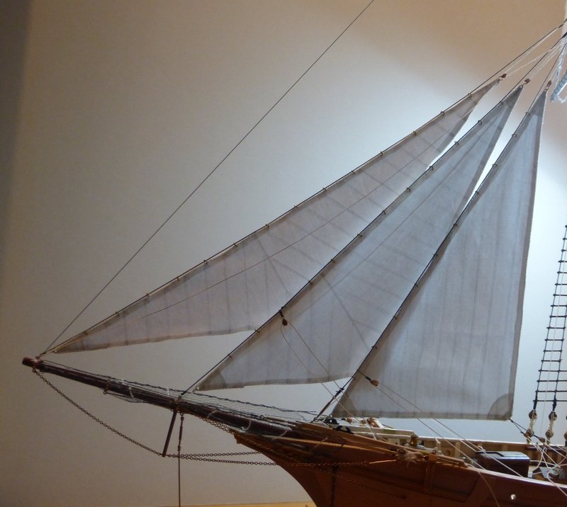
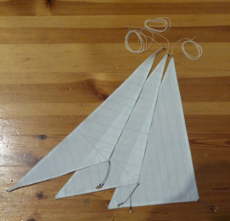
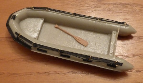
Thanks to Michael, Markku and Popeye for the support, this has become a really enjoyable build. It does not seem that I have made much progress since my last update, though it seems to have been a long time. But I have now completed the next 3 sails. I am really enjoying making these and by now the process is going smoothly. By far the most time consuming part is sowing on the bolt rope, but my stitching is getting better and is much more even than when I started. I am now ready for the final 4 sails which in general will be done in a similar way, it is just they are larger and not triangular. However before moving on to these I will concentrate on the fore yard and the fore topsail yard. I think I need to get these in place before I hoist any canvas. The following picture shows the 3 new sails in the relative positions they will be in on the ship. The rope at the top of each is the downhaul, mounted on a ring which also contains a block for the halyard. There is a ring at the bottom of each for the tack. The downhauls are routed to blocks set on alternate sides of the bowsprit by their respective tack. Port for the outer jib, etc.. The other cables with blocks are the respective port and starboard sheet pendants. I keep promising myself that I will finish off some of the other bits and pieces I have started, but the problem is that I have been enjoying sail making too much. However after finishing the above, as a return to working in wood I have been attempting to make a paddle for the ships boat. This is my 4th attempt and the first one to be completed in 1 piece. It is 22mm long. It is made from some 3mm x 1mm walnut strip (because it was readily to hand) using the following process. I started by scraping each side for a 20mm length at the end of the strip, to reduce the thickness such that there was an obvious ridge down the centre of each side. I then used a scalpel to remove the unwanted bits each side of the shaft while shaping the flare between the shaft and the blade. I then sanded the end of the blade so the tip was curved. I then removed the ridge on each side at the end of the blade towards the tip. Then I sanded/scraped the shaft into a circular profile while also giving other areas a light sanding. All this was done while still attached to the strip. Finally I cut the paddle off the strip 2mm above the end of the shaft and fashioned this bit into the handle. Having done all this a few times, generally improving, I will find some better wood and have another go. I first need to make up a 3mm x 1mm strip, possibly from boxwood or lime. Though I do also have some other unidentified bits of close grained wood lying around that I may try. I have now got to a point where I have managed to compile a list of outstanding jobs, must mean I am closing in on the finish line. It's probably not complete, but this is it. · Make more blocks as required · Make more rigging cord as required 1. Outer Jib (Granf Foc) rigging 2. Inner Jib (Petit Foc) rigging 3. Fore stay sail (Trinquette) rigging 4. Anchors (2 + 1 spare) 5. Fore Topsail (Hunier) + rigging 6. Fore yard + rigging 7. Fore topsail yard + rigging 8. Foresail (Misaine) + rigging 9. Topmast stay sail (Voile D’etai) rigging 10. Radome 11. Finish Ships launch / Inflatable. 12. Rig davits 13. Mainsail boom + rigging 14. Mainsail gaff + rigging 15. Mainsail (Grand Voile) + rigging 16. Gaff topsail (Fleche) + rigging 17. Rear decoration (painting) 18. Ensign 19. Binnacle: I have decided to paint this white and see if I can print out a suitable 6mm compass dial for it. 20. Life belts 21. Entrance way gates (whatever these are called). 22. Poop deck railings 23. Missing ratlines Thanks to everyone for looking in especially those that hit the like button. Glenn
- 101 replies
-
- 6
-
-
- L Toile
- Billing Boats
- (and 1 more)