HOLIDAY DONATION DRIVE - SUPPORT MSW - DO YOUR PART TO KEEP THIS GREAT FORUM GOING! (Only 69 donations so far out of 49,000 members - Can we at least get 100? C'mon guys!)
×


glennreader
-
Posts
136 -
Joined
-
Last visited
Content Type
Profiles
Forums
Gallery
Events
Everything posted by glennreader
-
 Steve, I made a couple of these a few years back. Hear are a few tips: Lose the black paper. For the ribs use some thin wooden strip instead, it looks much better. I could not get that bit of wood they supply as a floor to fit in any of them. I replaced this with a few planks run along the length on top of the wood ribs. Find some pictures or drawings of the real things. Try and add the fittings for masts, knees etc. Gratings always help. I just used 0.5mm strips at right angles. Its difficult to tell the difference when they are that small and thin. I have got one that's not finished yet, I will take a couple of pictures this evening and post them to show you what I mean. You are making a good job of the Billings kit. I have also found it necessary to replace some of the supplied parts. I see from your pictures that the blocks and deadeyes they supply are the same ones as supplied on my model even though the ships they represent were launched 150 years apart. Glenn
- 291 replies
-
- 4
-

-
- bounty
- billing boats
- (and 1 more)
-
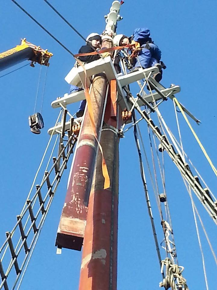
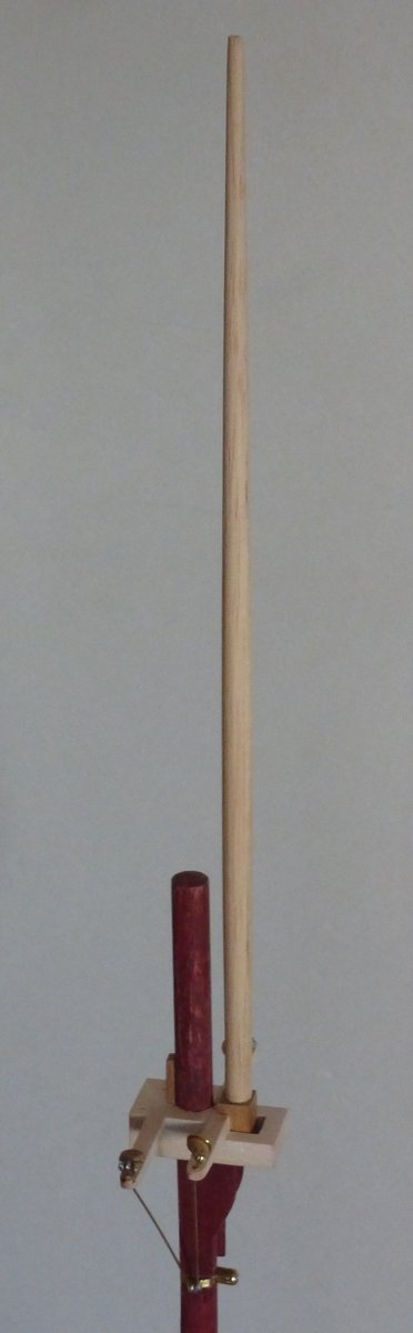
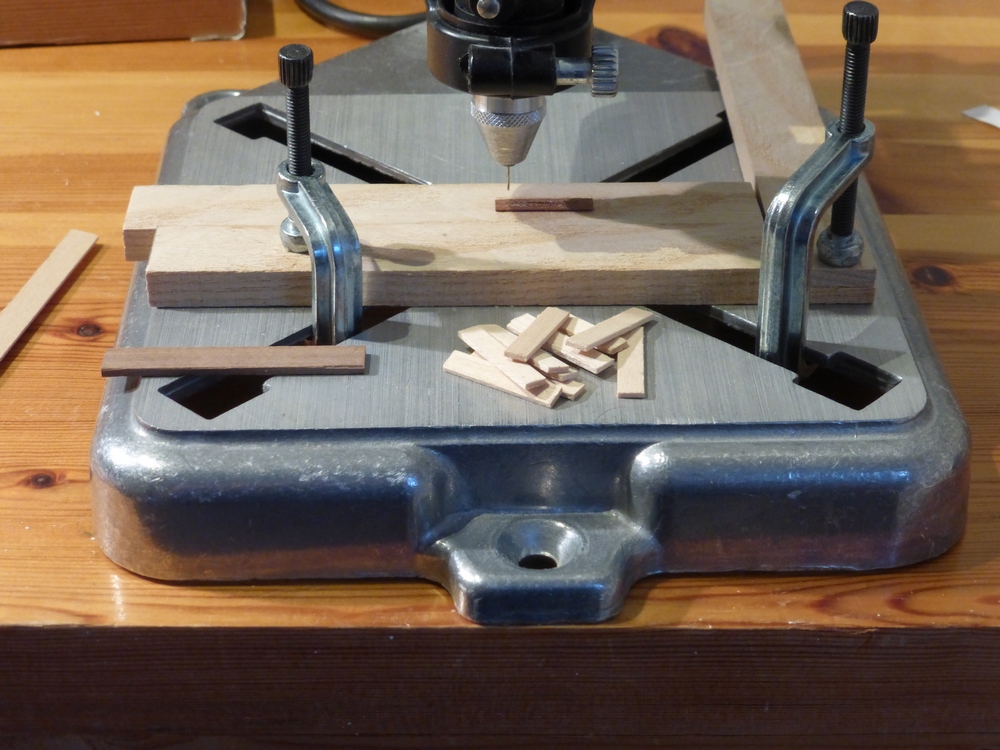
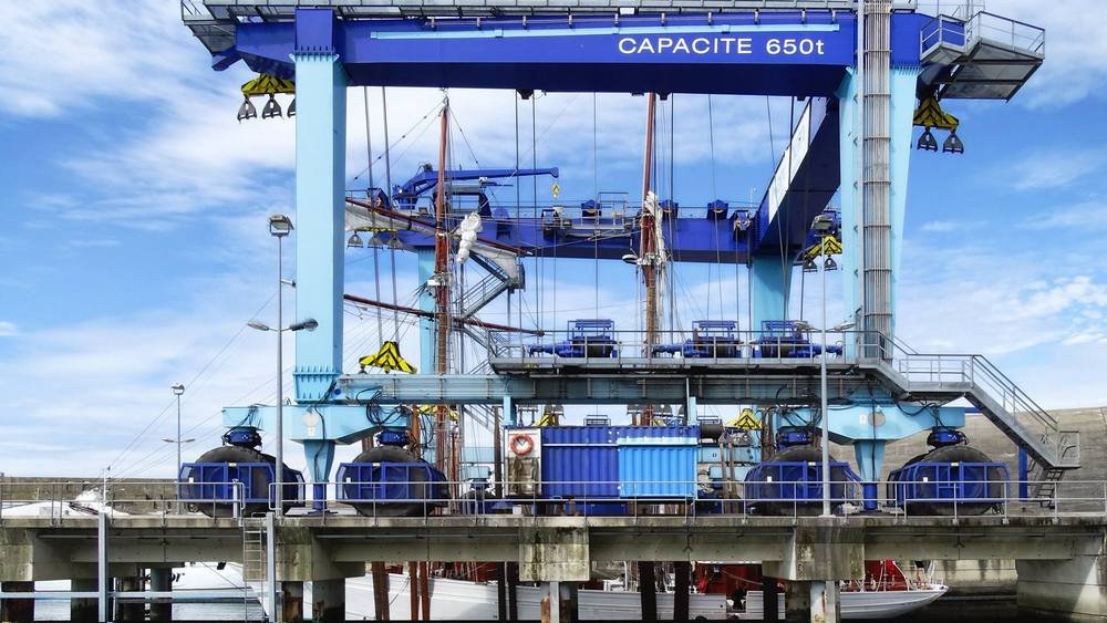
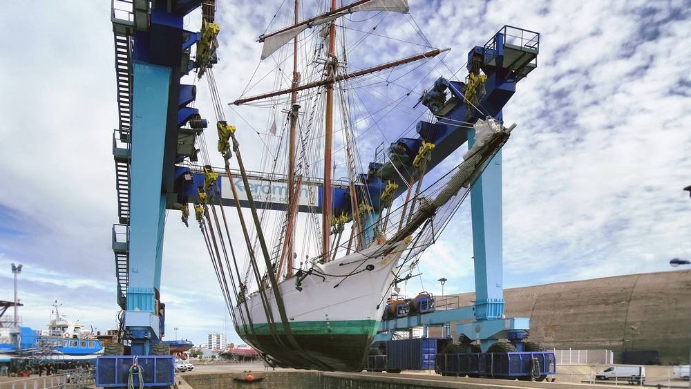
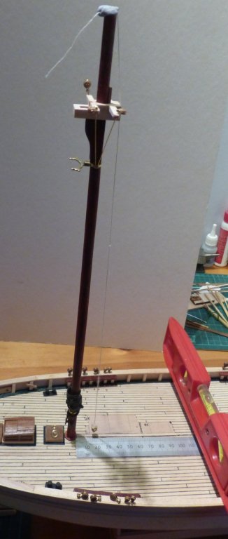
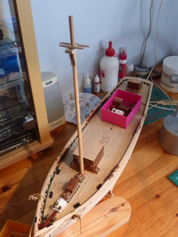
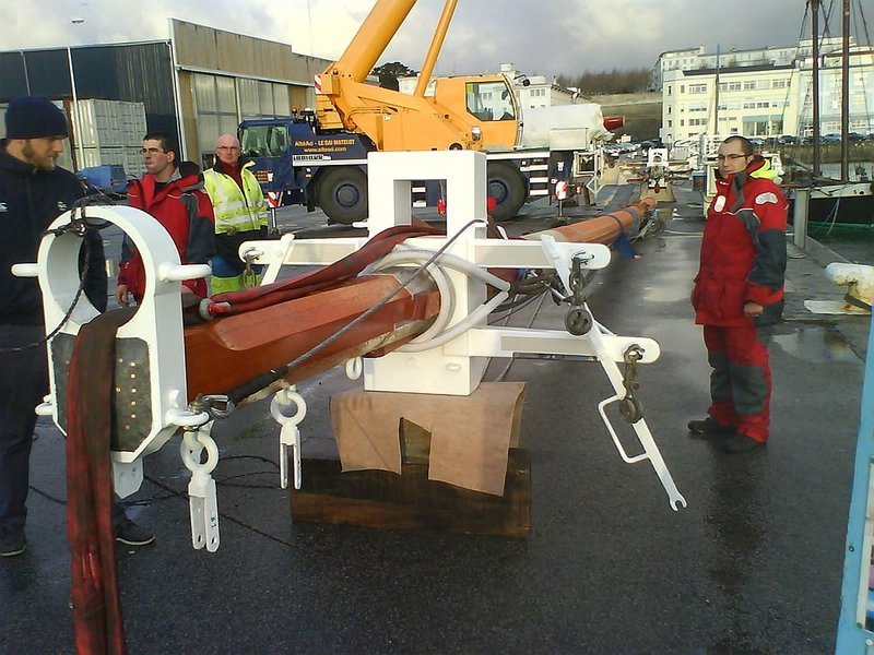
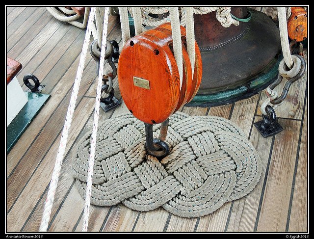
Things are going slowly at present. I am being held up by the lack of the right coloured rigging cord; with the appearance of steel rope. The bit I need for my rope walk has not arrived. I checked up on Amazon and discovered that delivery is 1 month. I did not bother to check when I ordered, I just assume anything I order from Amazon arrives before I log off. This means I am trying to get on with some of those tasks I have been putting off. Normally I put off something because I am not sure what is required, how to do it, or I am not sure how much I can include at this scale. One of these problems was exactly how the top masts are mounted. With the new pictures I have obtained I have now solved this. You can see in this picture that the top mast is offset from the square hole in the top. Also from a picture I posted in my last post, of the mast lying on the ground, that hole is just too far forward. It is there for the top mast to be raised through when it is stepped. But if that is all it was for why bother? It is also possible to see that the top mast is square at the bottom. Something that the supplied part is not. My assumption at this point was that the top mast sits on the top just back from the hole overlapping it and a block of wood is fitted into the hole. But then how is the mast held in place? The answer is simple. It can be seen in this picture that there is a block in the hole, and in the next picture that the bottom of the top mast is not square. It has been cut so there is a lip that rests on the head with the section below in the square hole. Then once a block is knocked in to fill the hole the mast is held securely in place. Also in the first picture, a slot can be seen near the bottom of the mast. I have wondered what that is for. In the picture below it looks like the rope used to raise the mast into position goes through it. I have now fitted a square section to the bottom of the supplied mast. I first drilled a 2mm hole in both bits and strengthened the joint with some bamboo. I then shaped the square section as required. This also had the effect of lengthening the top mast by about 9mm, which was useful as the supplied part was about 6mm too short. Going back to my previous post where I pointed out the half circular cut out just behind the square hole. This was where the round version of the top mast sat. I have now enlarged this to make it rectangular so the square bottom of the new top mast sits snuggly in it, with a section going down through the square hole. Its only dropped in place in this picture, it goes closer to the fore mast giving a more realistic gap. Now when I mount the top mast permanently I will insert a small block to fill the rest of the hole. Problem solved. I hope that once stained the difference in materials will be hidden. To divert slightly. How do you lift one of these? Answer, with one of these. Glenn


- 101 replies
-
- 4
-
-
- L Toile
- Billing Boats
- (and 1 more)
-
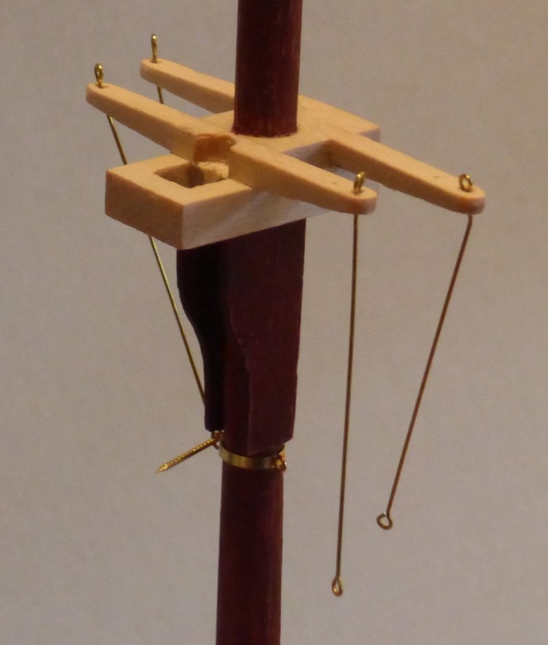
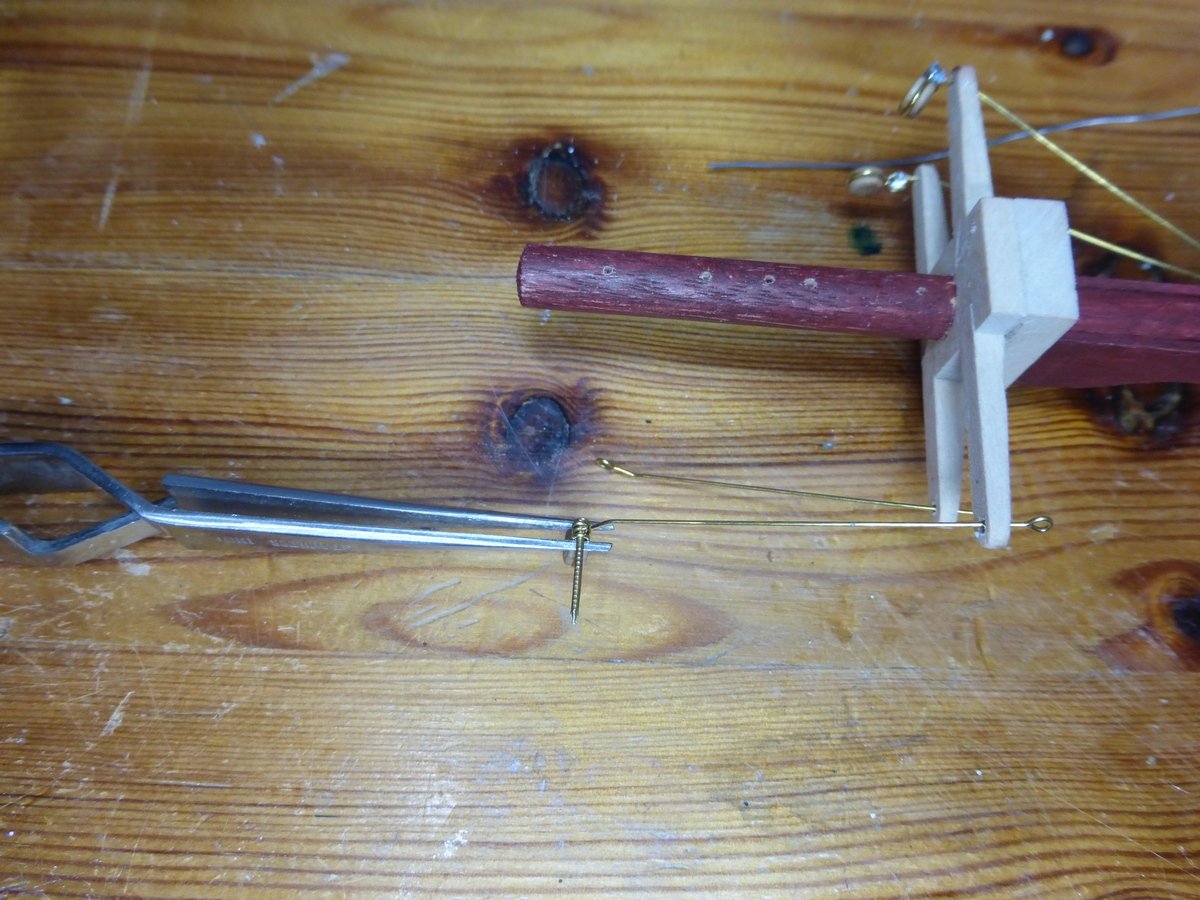
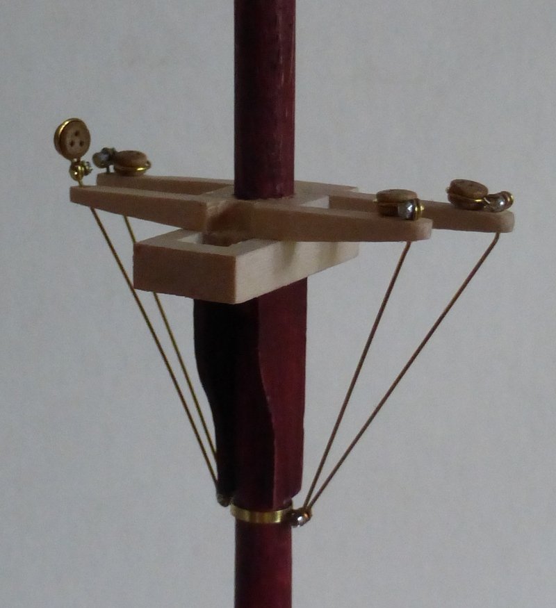
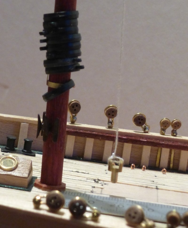
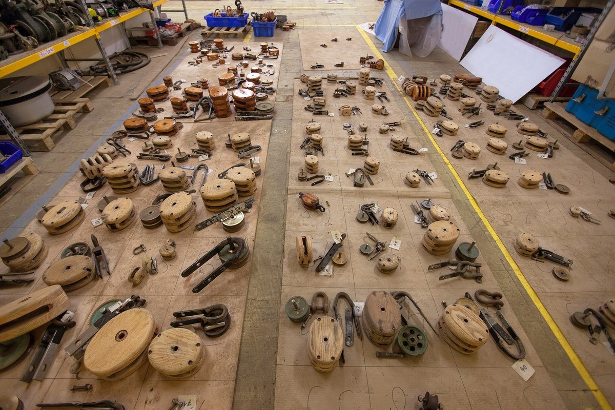
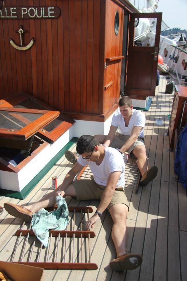
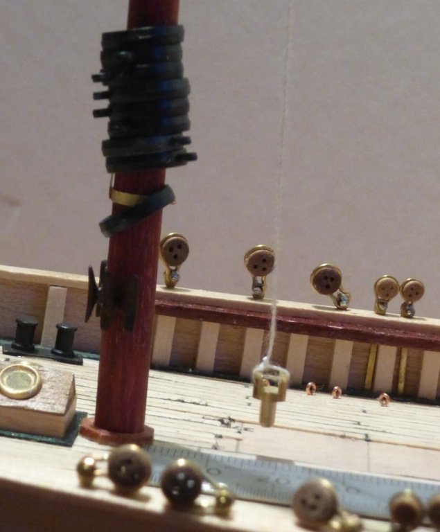
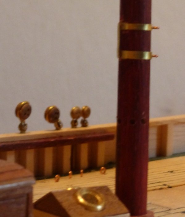
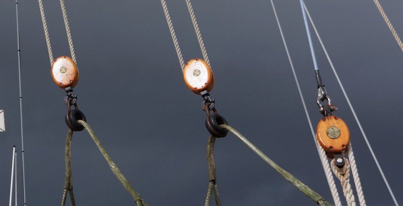
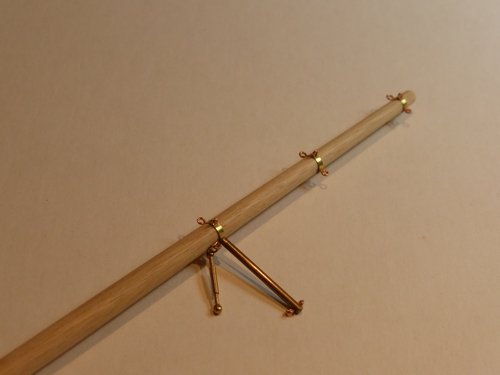
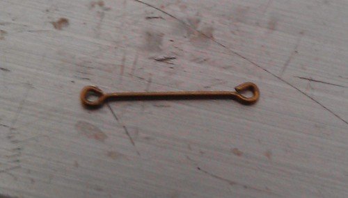
The next step was to stain the mast burgundy, like the bowsprit, then give it a quick rub down. I then fixed a brass band just beneath the cheeks, with an eye pin inserted each side. At this stage I had forgotten about the truss for the yard and had to drill and fit that later. The futtock shrouds are then made from 0.5mm brass rod. Round nosed pliers were used to form an eye at one end. Then the distance from the eye pin on the mast to the spreader was measured and using small pliers the rod was bent this far in from the eye. Then from experience I know that an eye in rod this thick uses 4.5mm of material and the spreader is 2mm thick. Therefore the rod was cut off 6.5mm from the bend. This was then inserted through the hole in the end of the spreader and another eye formed on the working end. It took a couple of hours to do all 4 which surprised me. Note the half circular cut out just behind the square hole. Keep this in mind for a future post, all will be explained. Then using the same brass rod I made up 4 of these for the deadeyes. This is done in a similar way. Make an eye on the end of the rod. Then cut this off the rod 16mm from the eye, 11.5mm to go round the deadeye and 4.5mm for the eye at the other end. Make the eye on the other end and then bend each eye back at a right angle, finally form it round a drill shaft. This is then all assembled using brass nails. Here is an example of how I solder these in place. The cross over tweezers hold it all in position while solder is applied to the side opposite the head of the nail to solder the nail to the eye on that side. Fixing the futtock shrouds to the eye on each side of the mast was done similarly. It is really a matter of improvising something that works to hold the pieces together on a case by case basis. Those with keen eyes will notice a row of 5 holes drilled in the mast head. There should only be 3, I got the spacing wrong. Of the two in the wrong place, one will be covered by a brace for the fore stay and I will fill the other before touching up the staining. The alternative is to put an extra eye pin in the hole, there are always ones not being used in the rigging. For instance in pictures of the ship I can see a eye bolt under the rear port spreader with a pendant hanging from it. I have no idea what this is for as I have been unable to follow the rigging any further than the block on the pendant. It’s not in any rigging plan I have. I have now done about as much work as I can on the forward mast before actually mounting it, most eye pins will not be mounted until I can do so with the appropriate block or other fitting attached, so I had a dummy run. I have checked the waterline is correct forward-aft simply by measuring and port-starboard by using a spirit level. I then suspended a plumb line from the rear of the mast. When the mast is in the correct position this will fall 15mm behind the bottom of the mast. This ran smoothly, there is a little wiggle room for the mast, but it is easy to get it in the correct position and when it is it looks correctly aligned when sighted along with the bowsprit. However, now its all fitted together, I noticed that in position the mast hoops look very thick. So I took them off and measured them and found they are 2.5mm, at 1/50 scale about 5” on the real thing. I used rough sandpaper to reduce this to about 1mm. They look much better, but I do not have a picture yet. The only other work required was to fit something to hold the boom. This is 2 brass bands 6mm apart with an eye pin in the aft side of each and a brace between the 2 opposite. When it comes time to fit the boom it will be supported by a pin pushed into the 2 eye pins, which will then be able to move from side to side. sorry for the poor quality of this picture. However I have found a new source of pictures of the real thing. Each of the schooners has a Facebook page. I am not a great user of social media, hence it taking this long for me to find it. There are a lot of pictures of the last rebuild of the Belle Poule. I especially liked this one. How many different blocks do you have on your model? In my day you had to have done something naughty to get a job like this. Hope you enjoyed that. Again thanks to all those following and posting likes. It is encouraging. Glenn


- 101 replies
-
- 5
-
-
- L Toile
- Billing Boats
- (and 1 more)
-
Looks good. I really like the sails, especially the colour you have managed to achieve. Glenn
-
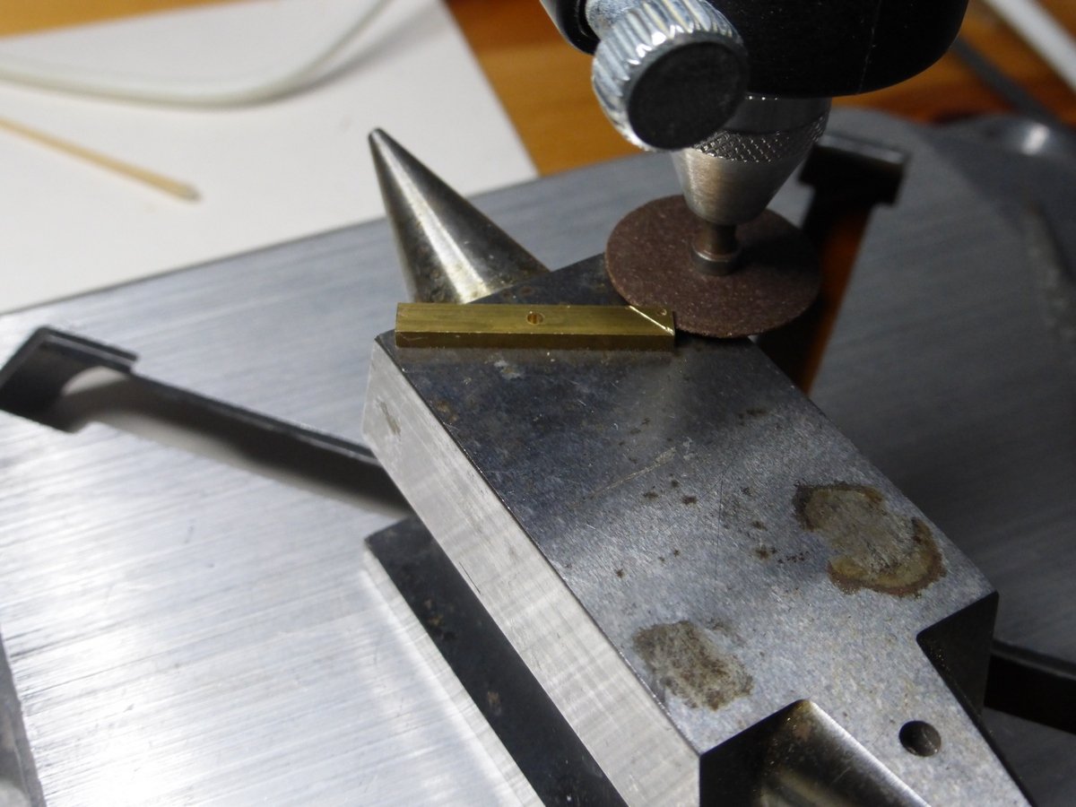
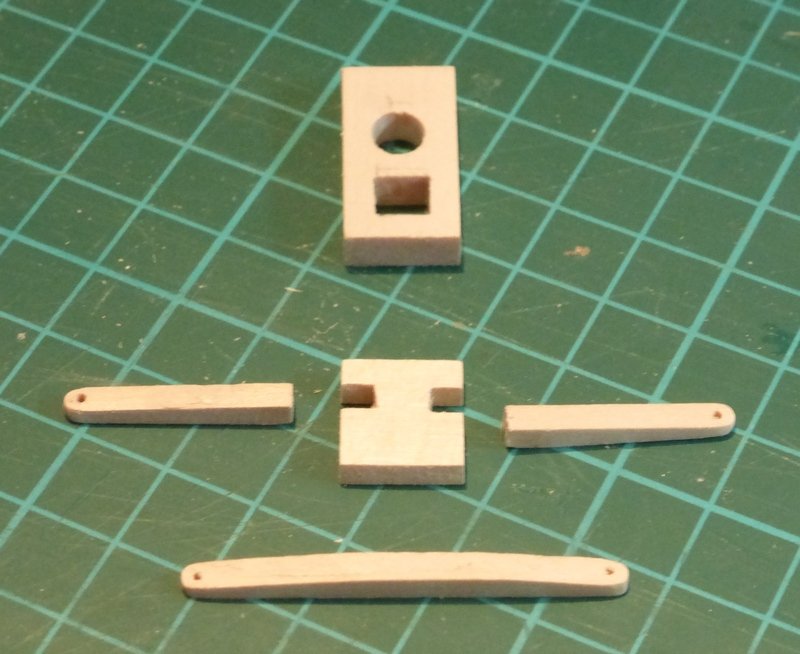
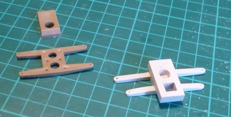
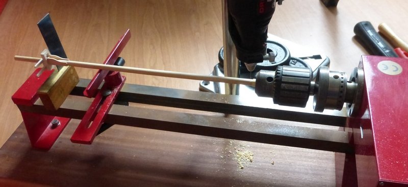
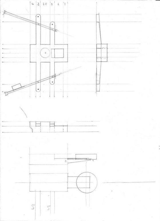
Thanks to everyone who has made a comment, given a like or just looked in. As it’s been a few days since my last post I thought I would do a quick update. I will start with the subject of ropewalks. I made one and I made some rope, but I was not happy with it; the rope was inconsistent. I am pretty sure that this was because I could not get a ball bearing swivel for the looper and the non-ball bearing one I could obtain locally was just not up to the job; it did not turn smoothly. I now have the required part on order and am awaiting delivery. So I will leave the subject of rope walks for the moment and move on. As I am stuck with finishing rigging the bowsprit and I have now installed everything on the deck forward of the foremast, I thought it is now time to start on the masts, in particular the foremast. This is what it is needed to make. Though as I will use the supplied piece of 8mm dowel, my version will not be an accurate representation. As this is different from the version supplied in the kit I drew some plans. At the top is the foremast top, drawn correctly. Then beneath that sketches of the mainmast top. Basically the mainmast top is the same as the foremast top except both spreaders are the same length, there are no topmast backstay spreaders and there is a radome mounted forward. I took relative dimensions from the photograph and assumed some dimensions would be unaltered to obtain a reference. Here, on the left, is what is supplied in the kit, except for the length of 8mm dowel which I will leave to your imagination. Considering the kit parts are plastic mouldings all of the spreaders are different lengths. The difference between the longest and the shortest is 2mm (10%). Next to this is my version made from some Basswood I managed to pick up. As I am in the UK it is more normal to find Lime, but as it states on the packaging 'Made in USA', I guess it is really Basswood. Having used it, the only difference I found is that it is white, where lime tends to yellow. It makes me wonder if some of the wood I have bought in the past as Lime is really Basswood. My version is made of 5 parts. I was going to try and make the spreaders for the rear stays out of brass, but I have decided I just do not have the tools for this, unless I whittle them from solid brass. So they will be wood, but given the chances of them getting broken I will leave off making and fitting them for the moment. The assembled mast looks like this. The cheeks are from some 1mm x 10mm lime I have. I cut 4 pieces to the correct length and clamped them between 2 of the supplied plastic pieces. I then cut them out carefully with a jewellers saw and finished them with sandpaper. Things are really easy when a template is supplied. And in situ. Now for some metalwork. It needs a few holes. This time I am using the indexing ring to space out holes for cleats at 45 degrees. I am also using the tool rest to support the mast. The square is being used to set the initial position using the side of the top. That’s as far as I have got. Hopefully I will get a chance to finish this in the next few days Glenn
- 101 replies
-
- 5
-
-
- L Toile
- Billing Boats
- (and 1 more)
-
I really like the way you use the colour of the material, only using paint to enhance the decoration and make it stand out. I have been thinking about getting some of those hole pliers. It would probably be a good idea to get some in advance of them being required. Glenn
-
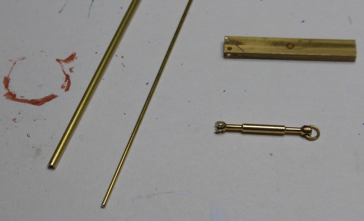
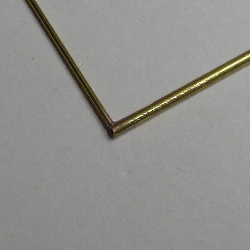
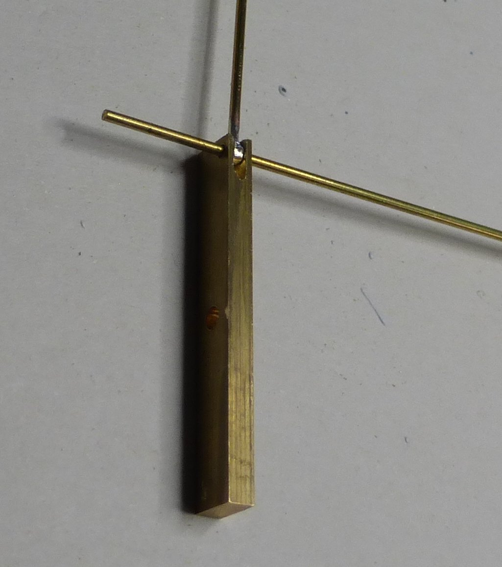
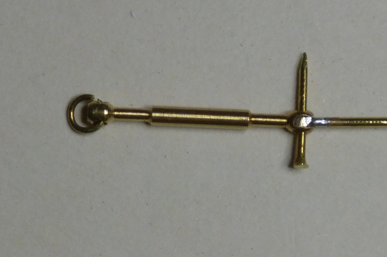
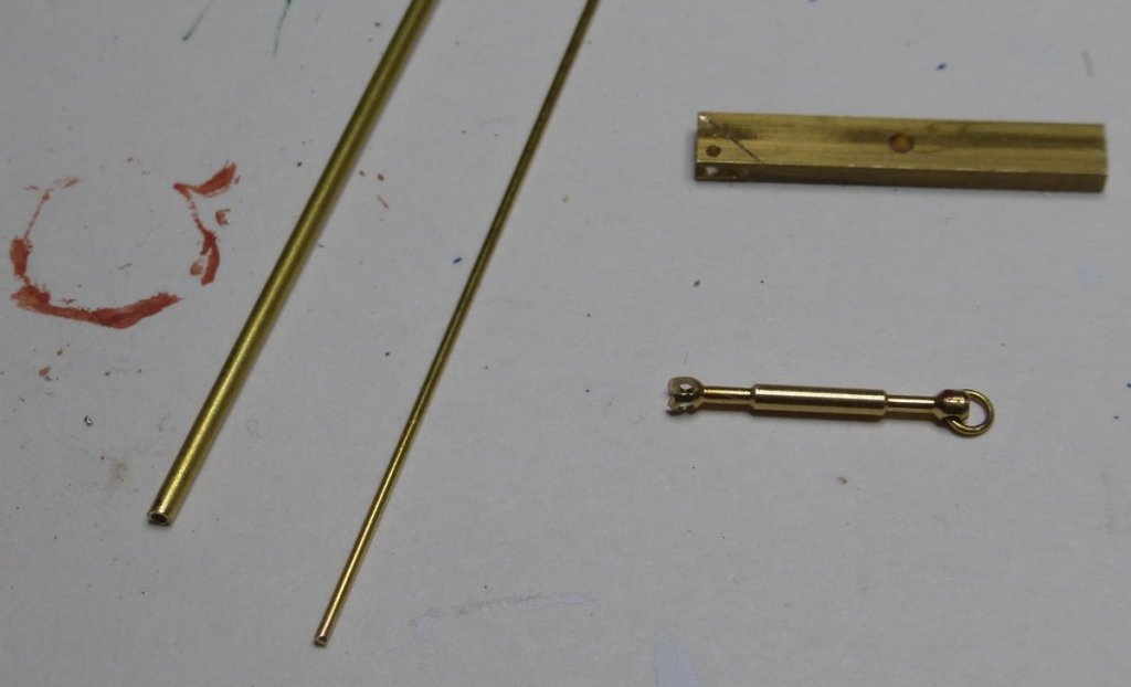
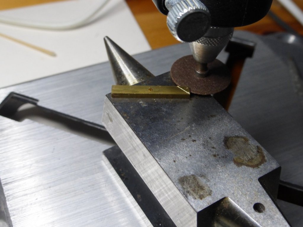
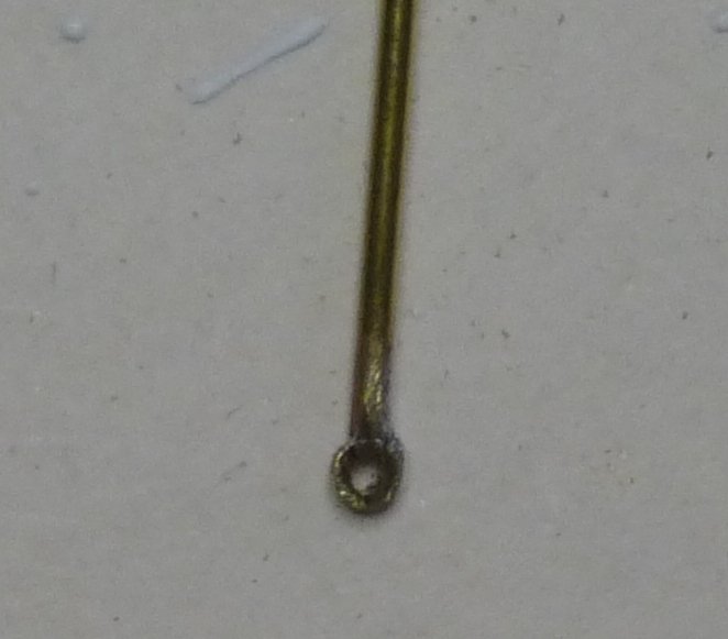
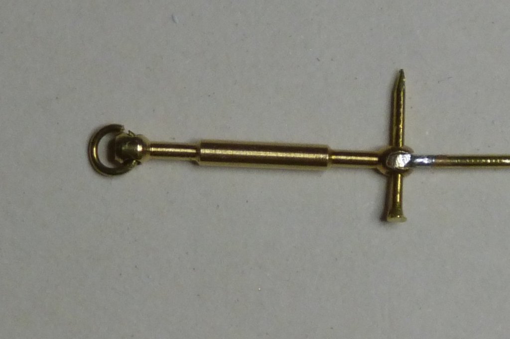
Michael, I guessed you had gone to see it. I could not imaging putting in all the effort you have in your build without ever having seen it. I have been trying to see if it is possible to visit either the Etoile or the Belle Poule, its sister ship, but there does not seem to be much information on their movements. Maybe because they are French navy. On with the build. I have completed the bobstay. I was pleased that my plan for this worked. Here is what I started with: A short bit of 2mm x 4mm brass not required. 0.75mm brass rod 1.5mm brass tube with 0.75 inside diameter. The bottle screw. The following image shows these pieces slightly later in the game. The bottlescrew supplied had ring ends. I converted one of these to a forked end while still leaving a hole in each of the two forks. This was done by first cutting a slot using a jeweller’s saw, then enlarging the slot with a cutting disk in the Dremel and finally a needle file. I cut the slot with the saw first to act as a guide for the Dremel. I then used a centre punch to mark the position for a hole near one corner of the piece of brass. This was about 1mm in from each edge, then I drilled this with a 0.8mm drill. I also scribed a line at 45 degrees from the adjacent corner as can be seen. I then cut a slot in this corner using the Dremel in a drill stand. This had to be deep enough to take the bobstay, but still leave some metal before the line. It was required that this slot was wider than the thickness of the Dremel cutting tool. To achieve this I adjusted the height carefully so that it was off centre then after 1 cut I turned the brass piece over and repeated the cut. This was done by eye. I later used the jewellers saw to cut this piece off along the scribed line. Then for the bobstay. I first cleaned up the ends of the rod and the tube and positioned them as shown below, at right angles poking over the edge of the table. I then soldered these together. Then again using the jewellers saw I cut off the end of the tube soldered to the rod. To prevent the teeth catching when I break through to the inside of the tube I slide a bit of rod inside. I then cleaned this up and tested the fit with the previously made parts. Not sure about including that last picture it looks awful at this size - must be before I cleaned it up I then needed to measure the length required I found it easiest to fit it to the triangular piece and measure to the bobstay, the result was the rod needed to be 92mm long. I realised that any slight error would just result in the triangular piece ending up slightly offset from where it should be. Probably by an unnoticeable amount. Having cut the rod to the correct length I repeated the process of soldering the tube to the other end and cutting it off. Unfortunately, in my excitement, I forgot to take a picture of this before it was fitted. Having got to this stage, it was then only required to replace the bottlescrew on its fitting behind the martingale, attach the triangle to one end of the bobstay and the other end to the bottlescrew. In both cases using a nail as a bolt, secured by a small drop of CA adhesive. Then using CA adhesive fix the triangular bit to the cutwater. At this point I have to admit I dropped the triangular bit when attaching it to the bob stay and could not find it, so the one used is the second attempt. I am quite pleased with the result. You never know what you can do until you try. I had been thinking about this for some time. Hopefully tomorrow will be 'make a ropewalk day'. Glenn


- 101 replies
-
- 9
-
-
- L Toile
- Billing Boats
- (and 1 more)
-
Thanks for pointing out chucks new blocks, I had spotted them myself, for the larger blocks they look really good, exactly what is needed. However he does not make them small enough for most of my requirements. I am not sure of his sizes, I think his smallest is 3/16" (4.5mm). Most of what I need are 2mm (1/12") and 3mm (1/8"). I do like the way he has inserted the metal strips and even doing two strips on the double block. I did think of doing a layered design, but I did not have any suitable wood and there would have been too much waste to saw the boxwood into 0.5mm strips. Thanks also for your other comments, I have been keeping my eye on your Wasa, a stunning build, I have not commented myself as so many others do. I was in Stockholm about 25 years ago on business and the person I was working with took me to see the ship. Fantastic. Glenn
- 101 replies
-
- 2
-
-
- L Toile
- Billing Boats
- (and 1 more)
-
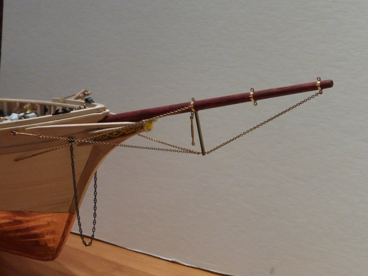
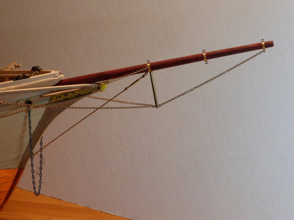
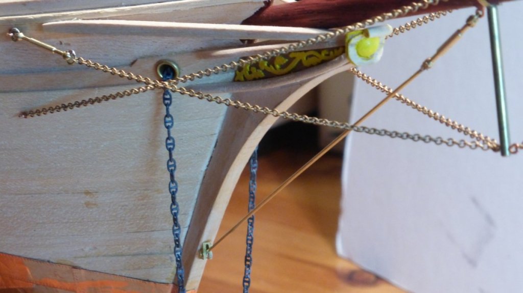
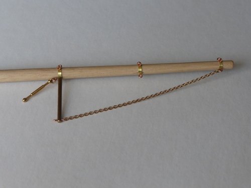
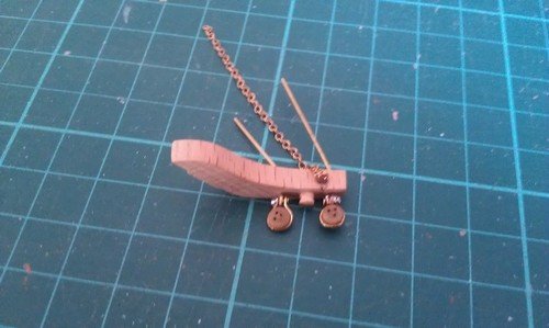
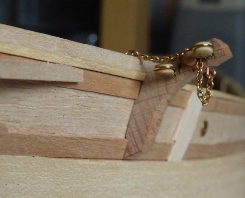
A quick update. I have finished mounting all permanent fixtures to the deck forward of the foremast. Before I progress further I want to make the fore mast and check its fit. The bottlescrews arrived so I have progressed with rigging the bowsprit. It was a lot of effort to make those chains look tight. Either they hung down or if I removed 1 link they did not reach. Eventually I had to stretch the fitting at the bottom of the martingale. But I did not get very far. The rest of the rigging on the bowsprit needs to simulate steel cable. This is a problem I have been pondering for some time along with the rest of the rigging which uses rope made from synthetic fibres and is white in colour. I have been trying different materials. I tried some 7 strand 0.4mm steel cable, unfortunately this would not bend tightly enough to look correct at each end though it was fabulous in between. I did find a cable made out of copper finished to look like steel (sold for AFV towing cables), but it was sold in only short lengths and the total cost was prohibitive. That leaves using light grey rigging cord to simulate steel cable. So finishing rigging the bowsprit will have to wait until I make some. I had already decided that I would need to make white rigging cord for the synthetic rope. I need to make a ropewalk. The other problem here is fixing the Bobstay. The Instructions show a length of brass rod with one end attached to the bottlescrew on the bowsprit next to the martingale and the other end fixed to the cutwater with a bent chain plate. They give no clues on how this might actually be achieved. Especially attaching the brass wire to the bottlescrew. If we look at the real thing: we see that the end of the bottlescrew is forked and the bobstay ends in such a way that it can be attached with a bolt. I should be able to replicate something like that. In the cutwater there is a triangular bracket which probably works in the same way. I think I can make one of these from a bit of 4mm brass I have from the old type radar system included in the kit, which was mounted on the deck and is replaced by a mast mounted system in the period I am building. So I will give that a go. That should keep me busy some time. Glenn

- 101 replies
-
- 10
-
-
- L Toile
- Billing Boats
- (and 1 more)
-
Just looked in micro-Mark. It's $14.95, which I think is a very good price for what you get. However it is then another $10.40 shipping to the UK, not so good. I might consider that if making my own proves to be a non starter. Thanks, for all the help. Glenn
-
Thanks for the information. I am familiar with the saw, it is even available this side of the pond, though I have something more conventional. I need a better mitre box and that looks a very good design, but I cannot find that it is available in the UK. After sleeping on it I still like the idea of trying to make one. I will continue thinking about it while looking around for suitable materials for such a project. I will also be following your progress here. Glenn
-
Very nice boats. I hope I can achieve something like that when I make boats for my Snake. Trying to be helpful and not sound patronising. To make small pieces like those rowlocks, I would do whatever I can, like filing the 45 degree angle, while the piece is still on the end of the stock, then cut it off and repeat. No having to work on really small bits. I like that mitre accessory, my one does not have an end stop. Is it home made? Next time I have a spare day I might try and make one. Glenn
-
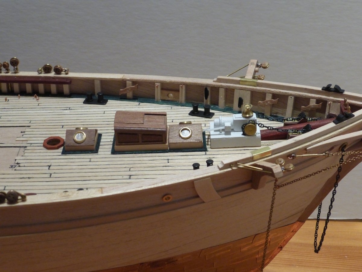
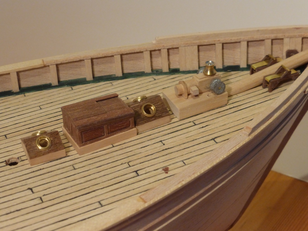
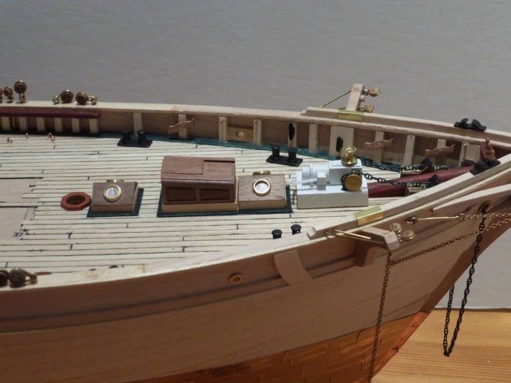
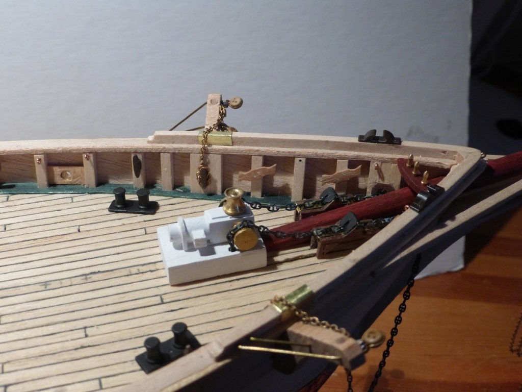
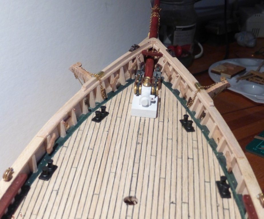
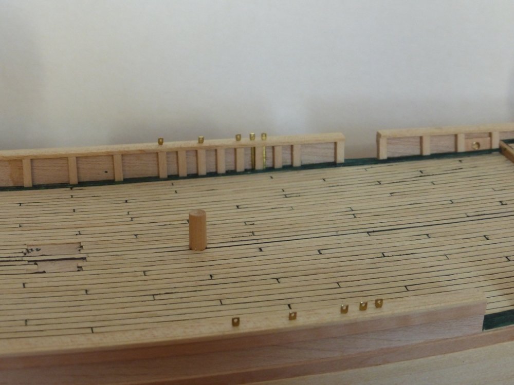
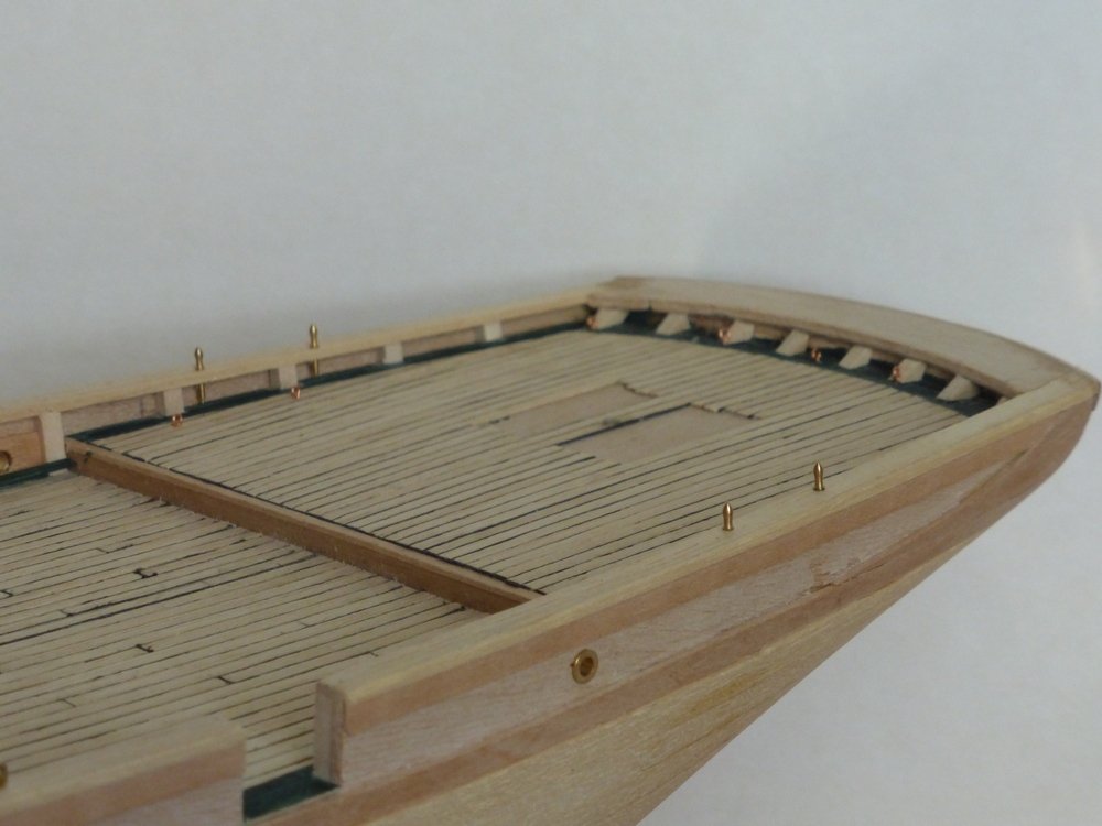
It is some time since I posted an update; as I said I have been busy with other things. However , during this period I have been making some of the required blocks. I have now made about 40 and have the process well worked out. I will now probably just make them to replace the ones I use. I can do the singles fairly quickly and that is the majority. I have started mounting the deck furniture at the stern and the bow. The stern is shown in the following two pictures. If you look carefully you can spot some of the blocks. The stanchions are just pushed into the predrilled holes. These are replacements for the kit supplied ones which only had provision for one rail. I had made a little jig, with a pilot hole, that hooked over the side and ensured the holes were drilled upright and in the right place. When pressed firmly against the side the hole would be the right distance in and a mark on the jig ensured that the correct position along the side could be easily set. This was thick enough to ensure the hole would be drilled vertically. When I was pushing the stanchions into place, for this picture I realised I had only drilled one side and as the jig had just been made for the task it had been discarded. However I never throw anything like this away and I eventually found it in a box of small bits of scrap wood. Phew. In the bow, so far, I have mounted the bowsprit, the chain gear and the bollards. The chain gear having been made from scratch to replace that supplied in the kit, which was out of date for the period I am modelling. My intention was to rig the bowsprit, but then I realised that I needed 3 bottlescrews, which I do not have. I am now waiting for them and a few other bits and pieces to arrive from Cornwall model boats. Some time ago I had ordered some Caldercraft stud link anchor chain, to replace the ordinary chain supplied in the kit. I blackened this with Carrs products. I first cleaned it in Acidip, then used Metal Black and finally Electrofix. I then threaded this chain in a loop through both sides of the chain winch, the chain stoppers and the Hawse holes and then mounted these on the deck cutting off the excess chain from underneath the winch, where it is secured. This means that at present a length of chain just loops round from one side to the other. It will be left like that until it is time to hang the anchors, which is some way off. The bollards were more of a problem than the chain. The metal black did not work as well, it left a bright brass circle where each bollard fitted into the base plate. All I can think of is there may have been some residual flux from the soldering. I used Caldercraft Matt (Metal) Black paint to touch these up. I really recommend this for metal, it is very effective. I have also started work on both the central companionway hatch and the machine hatch. But as neither is finished I will leave them to my next update. Thanks to everyone that has given me a like, Glenn
- 101 replies
-
- 8
-
-
- L Toile
- Billing Boats
- (and 1 more)
-
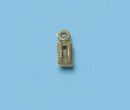
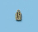
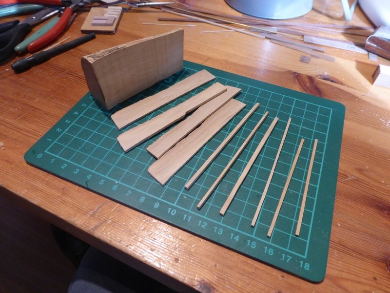
Eric, thanks for the comment. It defiantly makes a change to make a model of something that you can get photographs of. It’s been some time since I was able to do an update. I have been busy with other things this month. As I have been unable to spend much time in the workshop I have been able to study the rigging plans, work out what needs to be done there and count how many blocks I need to make: 133. Though I think I might find a few more along the way. I have also drawn individual rigging plans for each sail. I had decided to make my own blocks some time ago, as I am not happy with the plastic ones supplied (pictures curtesy of CMB website). They only supply 1 size and no triples at all. I cannot find any commercial ones that do not have slots down the sides for a strap. Examples of the types of block I need are shown below. Incidentally I also need white rigging cord. I will probably end up ignoring the fact that some of the rigging is wire and some is chain. I am using boxwood to make the blocks. I bought a 3” branch many years ago and still have a small quantity left. The first job was to cut some small billets of different thicknesses for different sized blocks with either 1, 2 or 3 sheaves. In total I need · small single 47 · small double 1 · medium single 46 · medium double 12 · medium triple 3 · large single 2 · large double 2 · large triple 2 · others 18 Small are about 2.5mm, medium about 4mm and large 5mm. Then I made a jig for drilling. It looks a bit Heath Robinsonish but it works. It makes it easy to drill the holes in the right place and at the right angle. The billets fit into the slots and once pushed home a hole is drilled. I use a pin vice as the jig is only wood and if I use a power drill I find it opens up the hole quite quickly. I then shape the block and do anything else required while the block is on the end of the billet. I am adding a small strap to one end, which can just been seen below on the bottom billet. Some require a hook instead. Then I saw off the completed block and it’s on to the next. I should get about 20 from each strip. I have made 20 so far of various sizes. I am improving; getting faster and they are becoming more symmetric. The most difficult and time consuming part is fixing on the small half strap with CA adhesive. They are not exactly like the real thing but I do not see how I could make the strap internal at this small size. As a final step some then require an eye-pin in the free end; so they can become half of a tackle. The thing about this is that even though I have little time at the present and will not have much time until the end of the month, it is possible to sneak off for 1/2 hour occasionally and make a few blocks. Hopefully by the time I get back into the workshop on a more regular basis I will have got most of the blocks I need. Head decoration Another task I have completed is the head decoration. I had a go at carving this earlier from a single block, without any success. This time I built it up from 3 pieces and am fairly happy with the result. Note, I have also stained the bowsprit, which was something I realised I had forgotten about before mounting all the metalwork. My next main task is to start permanently mounting all the deck furniture I have made. This will be possible as I will be able to mount the required blocks on the deck at the same time, which would otherwise be very difficult if I had to work around all the other stuff. Glenn
- 101 replies
-
- 8
-
-
- L Toile
- Billing Boats
- (and 1 more)
-
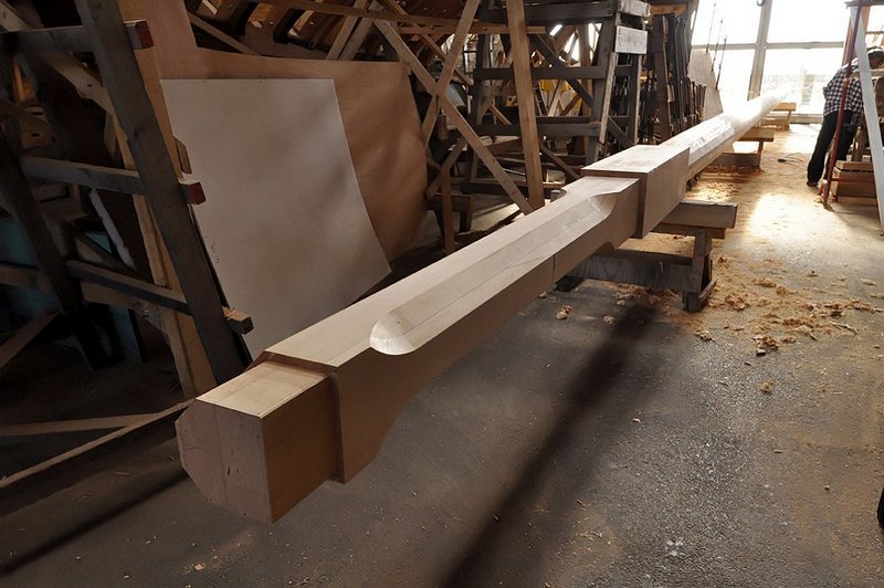
This all seems very familiar. I am currently making the Billings 'Etiole' and looking at your plans the method of constructing the hull looks the same. My main problem was that the spacing of the slots in the deck panel for the bulkheads did not match the plans. Hence when it was all assembled the fwd and aft pieces, parts no 2 and 3 in your picture, were a few mm further apart than shown on the plans which meant the strip of wood supplied for the keel was a few mm too short and I had to add a short spacer. I decided it was easier to make the model a few mm longer than shown on the plan rather than try and adjust everything else. In any case, who is to say which is correct. I think I am trying to say 'Proceed with caution'. Glenn
-
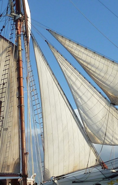
This rig is similar to that of the Etoile that I am currently making. The Etoile carries the sail in question, it is only used when running with the wind directly behind. When not in use it is not furled it is taken down and stowed out of the way. It is hoisted on two blocks, one at each end of the yard. The only other rigging is the sheets. There is a picture on my log showing this. It is in post #9, as it is in French the sail is labelled the Fortune (I am not sure how this translates). The vast majority of pictures I have found show the ship without this sail. Looking at the sail plan in your first post, this looks like a more permeant fitting, with all the rigging a square sail requires. But maybe if this sail was not used much the Captain had it taken down. In the end the rigging would have been up to the ships master. I am also having the same debate, whether to rig this sail or not. Though I am not as advanced as you; I am still working on the hull. My thoughts at the moment are to make this sail and see how it looks. With the minimal rigging involved it would be easily removed. Also I will include the tackle for hoisting this weather or not I actually rig the sail. I would like to make this model with the sails set and full of wind, which I think points towards leaving this sail off. This will be my first attempt at this, I do not know how successful I will be. I have been following your articles on sail making and am looking at taking a similar approach myself. I especially like how the panels of the sail look. I hope this is helpful, Glenn
- 96 replies
-
- 5
-
-
- topsail schooner
- revenue cutter
- (and 3 more)
-
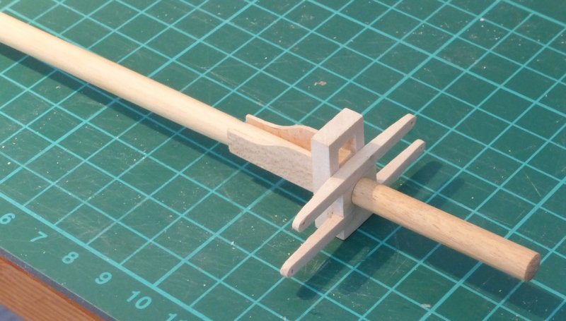
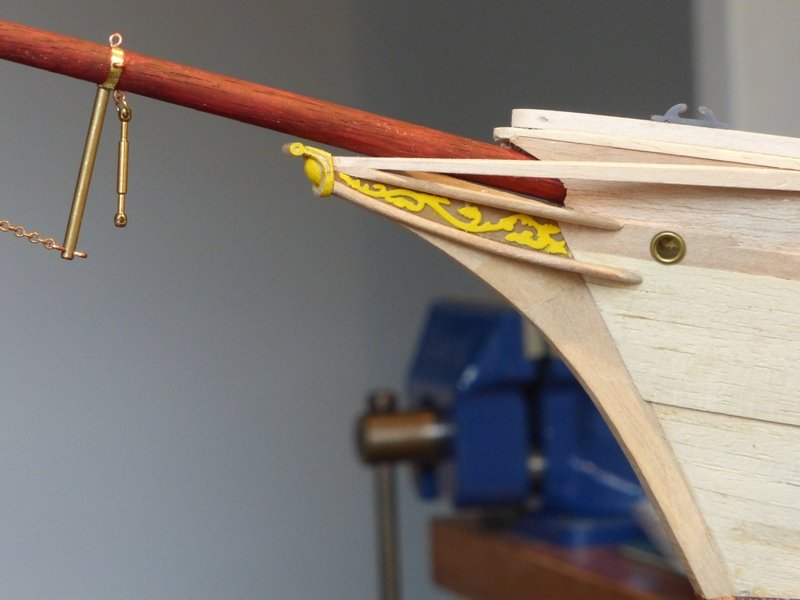
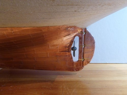
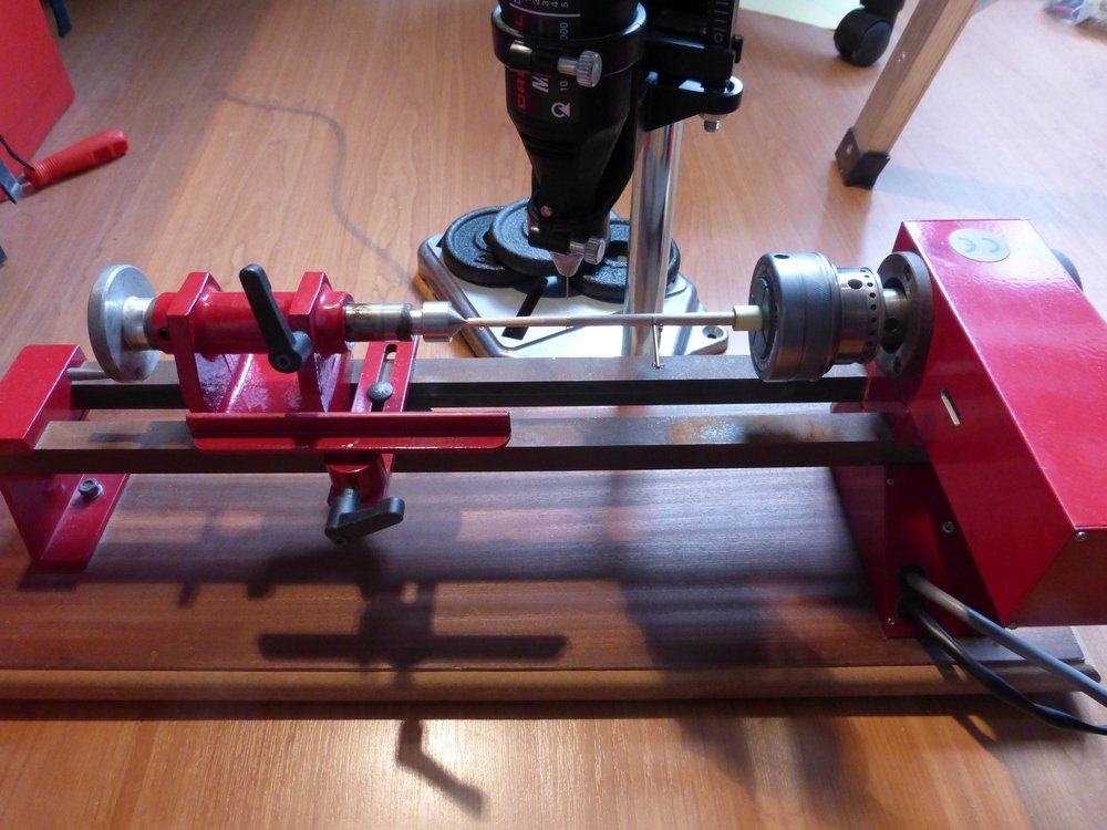
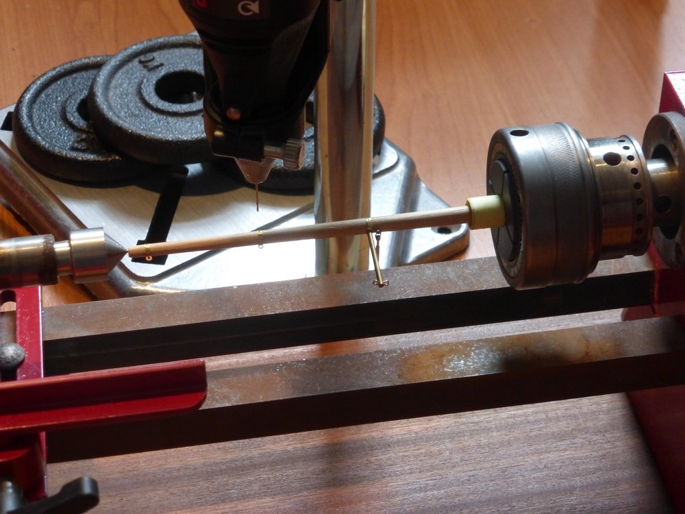
Thank you for the complement and to all those who have given me likes. Since my last update I have hung the rudder and made the bowsprit. I felt I needed a change from making deckhouses, skylights and suchlike. Rudder To hang the rudder I first had to make the gudgeons and the pintles. I had already decided I was not going to use the method suggested in the instructions which was only slightly better than bent nails and eye pins. Unfortunately I become so engrossed in this I forgot to take any pictures of the process. I first had to copper the rudder. Due to its shape this was not easy and the end result was very messy with CA glue everywhere. I have been trying to clean up any excess glue on the hull with acetone, but at this point I had been using some grade 0 wire wool for something else and decided to try that. This worked much better. It caught on a couple of corners which were not stuck properly, but this was quickly rectified. Very pleased with the result. I have some 1.5mm outside diameter brass tube with an inside diameter of 0.75mm. I also have some 0.75mm brass wire. I cut six 1.5mm lengths of the tube. To cut the tube I first inserted the wire. This prevents the teeth of the jewellers saw catching when you break through to the inside. I insert this from the far end and make sure it is not flush with the end I am cutting. This just makes it easier to push out the small piece of wire left inside the tube. I then cut some 1.5mm wide strips of 4 thou brass sheet. I just eye ball this as I cut this with scissors and know the blades are 2mm thick. I then solder this together. I solder the 1.5mm sections of tube to the strip by first inserting the wire which then holds the small piece of tube in place while soldering. Three of these also need a bit of the wire soldered inside, which is no problem, but with the other three care is needed to ensure that the wire does not get soldered inside. This turned out to be easier than I thought. After this I trimmed the wire projecting from the 3 pieces it had been soldered to too 1.5mm. Then it is just a matter of cutting the brass strips to the correct length and assembling everything. Bowsprit The bowsprit came pre-shaped from Billings. It was a little thick but I decided to leave it as supplied. It then needed 3 eye bands and the martingale fitted. Billings supplied 1 brass ring with 4 holes for one of these and a chain plate which was meant to be used for another, with no instructions how this was to be used. It was not the correct length and the holes were in the wrong place and there was only 3 of them. For the 3rd I think it was just expected to fit eye pins to the bowsprit. I decided to make all 3 from scratch so they would at least look the same. I first marked the position of the centre of each eye band on the bottom of the bowsprit. I then used the arrangement shown below to drill a hole for an eye pin in each of these positions. To explain this, I have mounted the bowsprit in the chuck for my lathe. This has an adaptor, like a collet, with an 11.5 mm central hole. I have wrapped one end of the bowsprit in paper to make it a snug fit and then positioned it such that the positions of the holes I need to drill are aligned with the slots in the collet. I have then positioned the Dremel drill stand such that when it is pushed up hard against the front of the lathe stand (this view is from the rear) the drill is positioned on the centre line of the bowsprit. I then positioned the lathe chuck so that the holes to drill are along the top and can then be drilled by moving the drill stand along the front of the lathe. This picture was actually taken later in the process. Here is a closer view of the same thing. I then drilled the three holes along the bottom of the bowsprit. Then I cut three small strips of paper, one for each eye band. I wrapped one of these round where each eye band will go, so the paper overlapped where each hole had been drilled and then pushed a pin through both layers of paper into the hole. I then cut some strips of brass with a width of 1.5mm from the 4 thou sheet and used the strips of paper as a template to drill two holes in each, one about 1mm from the end. I then wrapped these round the bowsprit and secured them using an eye pin in the holes just drilled, except for the inner one where I used the supplied martingale. I then trimmed the excess brass strip. It is best to leave this till now as it can be useful when securing the eye pin. Finally after taking the assembly off the lathe I drilled another hole, by hand for an eye pin to secure the bobstay. Then fitted a bottlescrew and all required eye pins.. The bobstay is meant to be made from brass wire. Again no instructions on how to attach this to the bottlescrew or the cut water. This is the first use I have made of my lathe for a number of years and I did not even have to plug it in. However I plan to use it to make the foremast and main mast. They both require tapering and holes drilled for cleats and such like. I will need some practice at spindle turning before I attempt that. After doing all this I have just been looking through 'The Ship Model Builder's Assistant'; first published in 1926. This has a much superior way of making eye bands. In my last post I gave a list of 6 jobs I still needed to do to complete the hull. I decided to rewrite this. I stopped at no 23, when I got to the bottom of the paper. Glenn
- 101 replies
-
- 9
-
-
- L Toile
- Billing Boats
- (and 1 more)
-
The other response is also valid aft, but I would recess the planks so the end is flush with the stern post. Cannot quite tell if they are in the picture. Depends on the width of the sternpost. Glenn
-
Your first picture is correct. Against the bulkheads. You will need to shape the edge that rests against the keel so there is not a gap. This plank is called the 'Garboard strake', the first plank on the ships bottom next to the keel. Also the edge of this plank will need to be shaped so it is flush with the keel. Also it will not extend all the way to ends, just to where the natural curve of the bottom of the hull extends to. In your bottom picture probable to the frame just aft of the number 9 on the plank. Forward it probably will extend to about where your black line ends in the last picture in your previous post. hope that is clear. Glenn
-
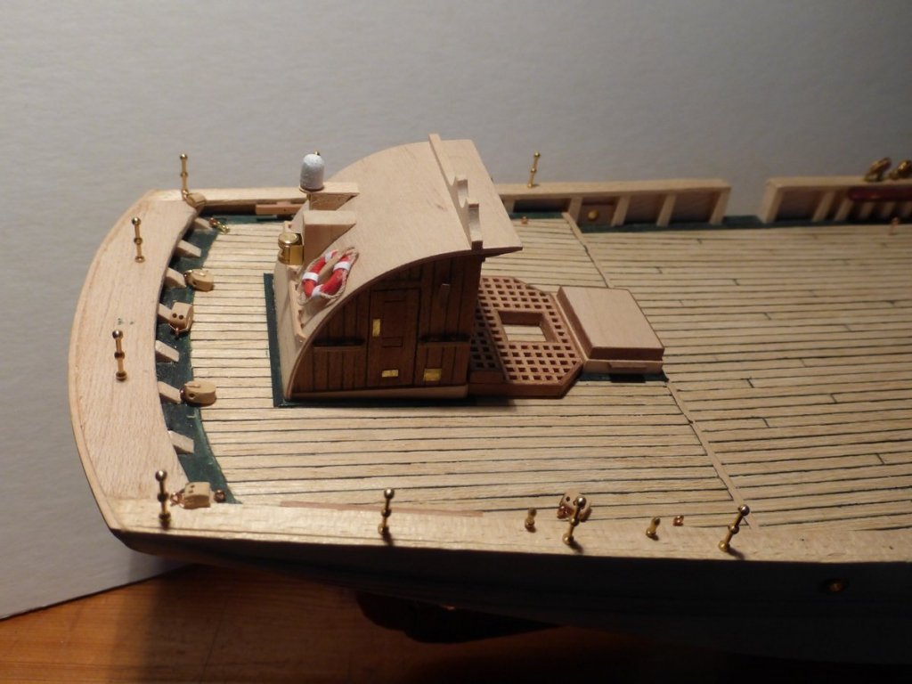
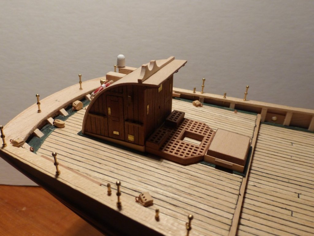
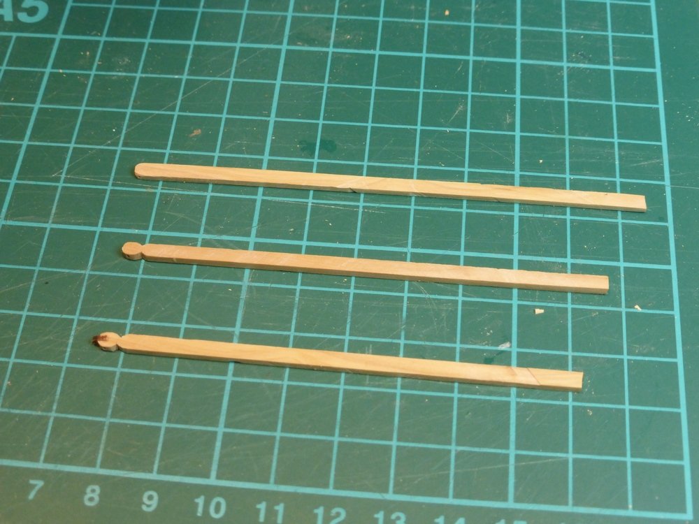
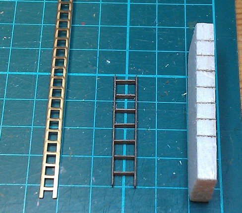
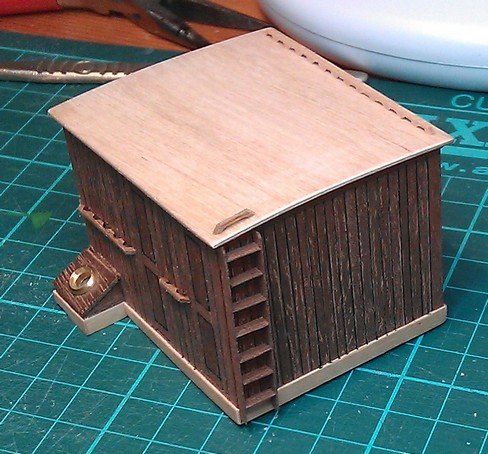
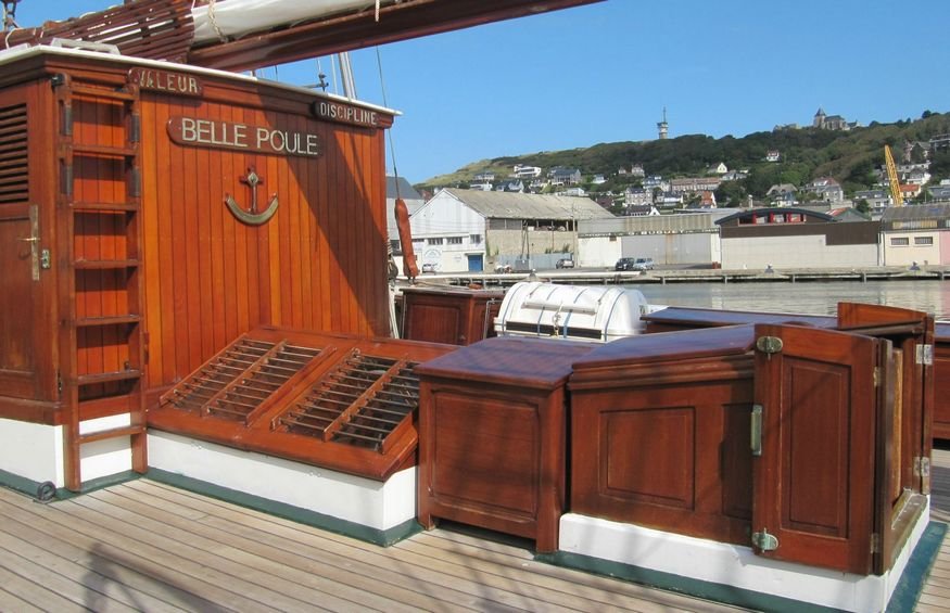
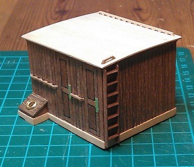
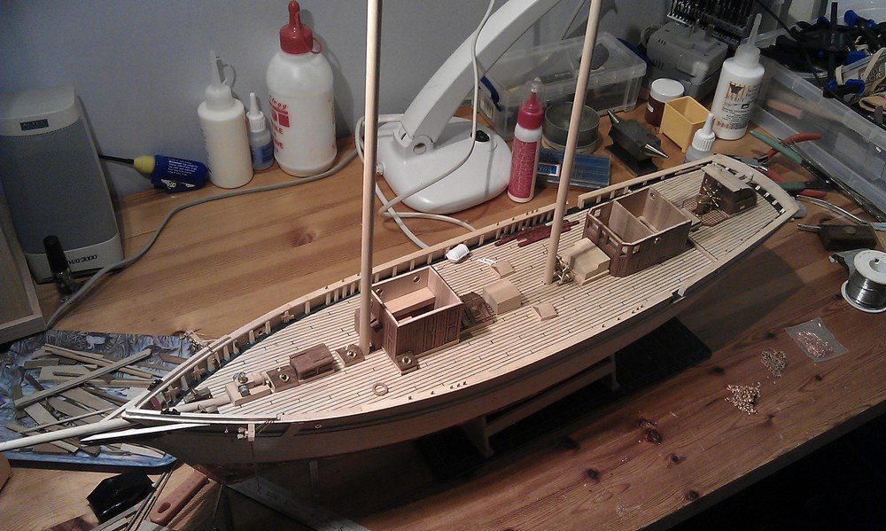
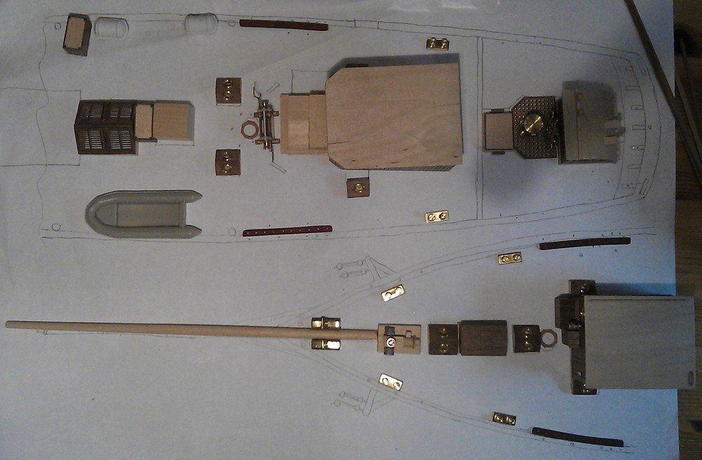
A quick update to show I have not been idle since my last post. Forward deckhouse I have finished the forward deckhouse. This involved replacing the supplied ladder, leading to the roof, with one of my own manufacture. The picture below shows, from the left, the supplied ladder material, the one I made with some leftover 2mm * 0.5mm material supplied in the kit and the former I used to make this. The steps for making the ladder were. · The rungs were all cut to 6.5mm length then inserted in the slits in the former, which were just made with a saw of the right thickness of cut. The former is about 1mm thinner than the length of the rungs, which therefore jut out slightly on each side. · This was then turned upside down and positioned on a flat surface and the rungs were all pushed down so they were flush with the surface. · The former was then turned on its side and pushed down so one end of each rung was flush with the former. The other ends are now clear of the former and a side piece can be glued in place without gluing anything to the former. This is done by turning it over so the rungs are again on a flat surface which is used to align the side piece. · Once this is set the first side piece is pushed in so that it is flush with the former and the other ends jut out. The second side piece is then glued in place. And here it is in place along with a view of the real thing. I have just spotted the ships name and the inclinometer there. Maybe I am not quite finished yet. I will have to see if I can print something out for the name and make something for the inclinometer. Still, here are a couple of pictures of it so far. Overview The following two views show how I am getting on overall. The Hull is almost finished I have the rudder to make and a few other bits and pieces. This view makes me feel I am making some progress. As for the deck furniture starting from the bow I need to finish the following, as shown in the picture below. · The chain winch. · 4 storage boxes. Two of these go along the starboard side with the life rafts, one goes between the grand skylight and the companionway hood and the last by the machine hatch. I have started two of these which can be seen without their tops. · The companionway hood. · The machine hatch. Not sure if I am translating this correctly from the French. It might mean the engine hatch. It's directly in front of the main deckhouse · The main deckhouse. · The ships boat and davits. And I thought I was getting close to finishing this stage and could start on the masts. This picture shows all the deck furniture on a sketch of the deck. This is to scale and it is traced from the main plans and shows the positions of all the rings fitted to the deck to take blocks. I will fix this to the deck and drill through to get everything in the correct place. most of them cannot be seen in this picture, there are 24 blocks of 7 different types attached to the deck. I could possibly include the bowsprit in this list as that will need to be in place to finish the deck. Glenn
- 101 replies
-
- 12
-
-
- L Toile
- Billing Boats
- (and 1 more)
-
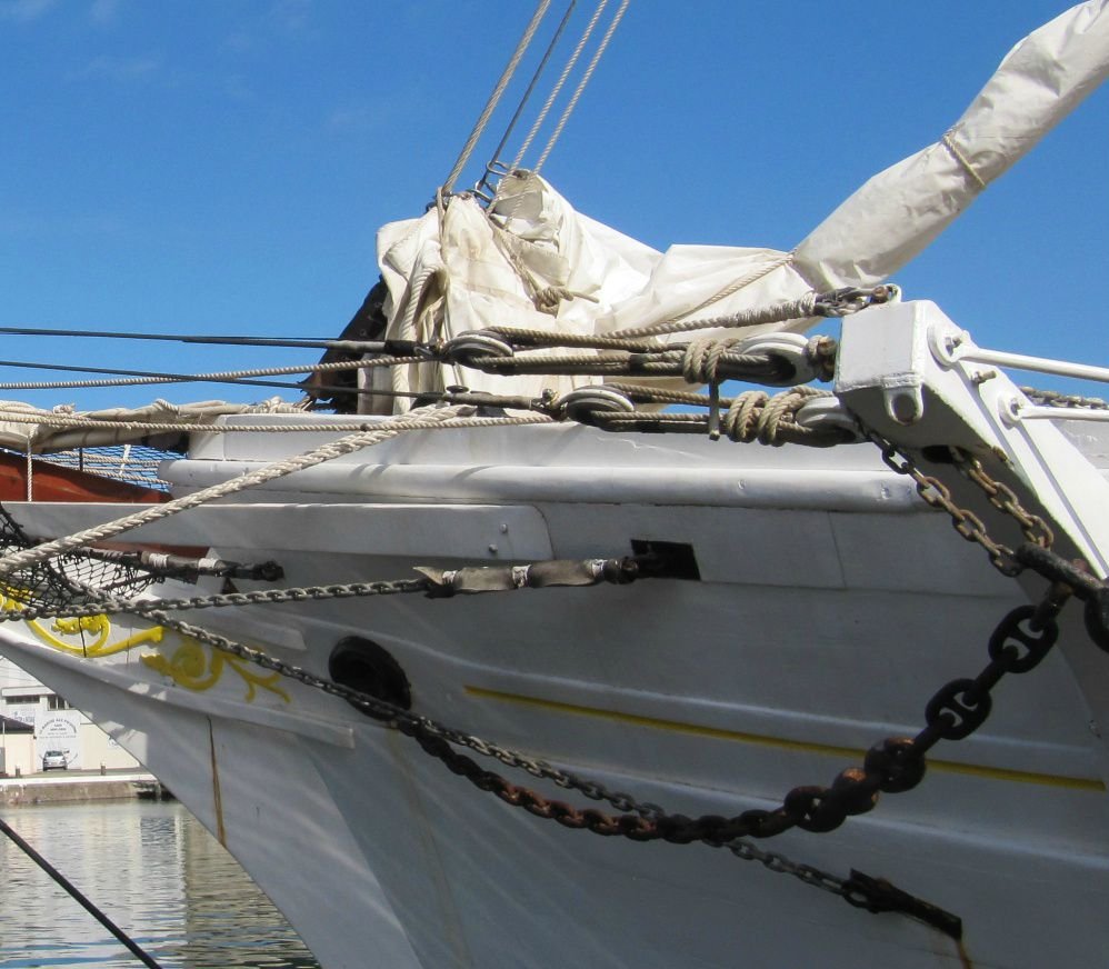
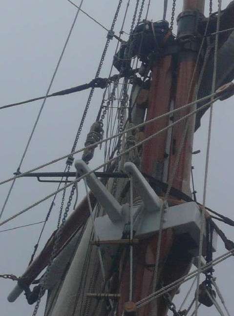
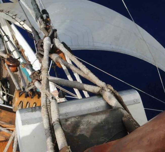
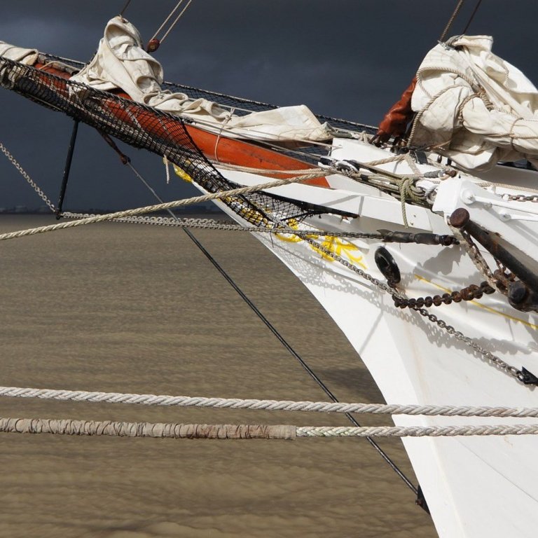
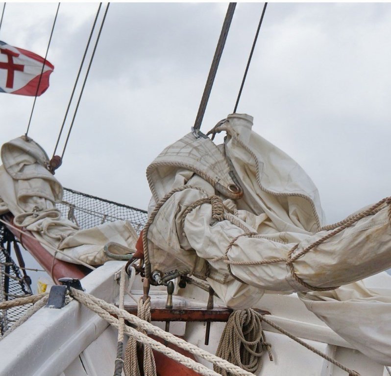
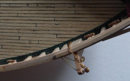
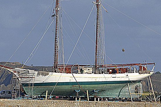
I have now finished the coppering and am quite pleased, at least with the second side. I still have the rudder to copper and to mount. I need to wait until I can get out and use my disk sander in the garage. I need this to taper the profile of the rudder and I am not allowed to use this in the house. This is the first time I have done this and I feel I learnt a great deal. I would like to think the next time I do this I will make a much better job. As can be seen I have made the catheads and mounted them. The supplied instructions do not provide much help. Also the shrouds they supply are plastic mouldings, which I am replacing with wooden ones. This was a bit of work deciding how to fix the shrouds. I think that in reality the bolts that hold these go through the cathead, which is made of metal, and then these bolts also act to attach the rear braces. In the end I decided to make these as 1 piece. I drilled a hole in the supplied cathead, I then put a loop in some 0.75mm brass wire which I threaded through this hole. Then when mounting this small assemble I shaped the wire as necessary to look like the rear braces. To attach the shrouds I worked out what length of 0.5mm wire I needed to make a loop on the end and using a bit of string, what the length round the shroud is. I then formed the required fittings as shown below. The final bend was done using the shaft of a 3.5mm drill. I then assembled these to the loops in the 0.75mm wire by using small brass planking nails as rivets and putting a blob of solder on to hold them in place. Now I have done these shrouds like this I have 20 more to do in a similar way for the shrouds that support the masts. Here are some more pictures of the completed catheads. Eventually the lose end of each chain will be wound round a metal cleat attached to the centre of the extra wide stanchion where the cathead is mounted. Notice I have also mounted those cleats I made earlier. They have been pinned and glued in place. I added the small rollers on the front of the catheads over which the anchor release chain passes. I have no idea, when raising the anchor how it is brought back into the stored position on the cathead. There seems to be no tackle for this, though in one of the pictures below there is a ring shown on the bottom of the cathead whose purpose is unknown. This also shows the rear of the cathead where the braces are attached. While I have been doing this I have been working out what eye rings, cleats etc. it is required to attach while the deck is clear making this easier. I have been doing drawings of the standing rigging and each sail showing associated attachment points for running rigging. One thing this has brought to light is that I do not know how the forward stay of the forward mast is set up. Looking in the following picture, a heavy steel rope can be seen descending from the forward mast masthead to the bow, the one that carries the staysail. This seems to go into a brown ‘package’. In the next two pictures this can be seen a bit more clearly, though obscured by the sail. This in turn seems to be retained by a couple of metal bars attached to timbers mounted on top of the rails. Not sure what these timbers are called. Is that it? In my eye they do not look nearly strong enough to take the strain of that heavy steel rope. Also is there something hidden in that brown stuff (leather?) that is used to tension this? Comments please. As suggested my next job is to fit any eye bolts, cleats etc. that can be identified and to fit the shrouds for the foremast and mainmast. After that I think it will be time to start fitting all the deck furniture I have been making. Glenn


- 101 replies
-
- 9
-
-
- L Toile
- Billing Boats
- (and 1 more)
-
Just found this thread. The HMS Trincomalee trust used to do a set of plans. I know this as I have a set. But I could not find them on a quick look on the web. Most are at, I think, 1/144 scale and would not be sufficient to make a model. There at 10 A4 sheets giving deck plans and frames and a single A3 sheet giving an overall drawing including masts and some rigging. One of the A4 sheets is a body plan at, again I think, 1/48 scale. The problem is that most of the sheets, although well drawn do not show a scale. The A3 sheet gives a scale of 1/8" to 1 foot, but it is obvious that that is the scale it was originally drawn at and it has been reduced. Having these would greatly reduce what other more expensive plans were required. I cannot remember what I paid for these, but it was minimal. Defiantly less than £10. A word of warning, if doing a search on the Royal museums Greenwich collections its spelt Trinocomalee. Its easier to search for Leda. Glenn
-
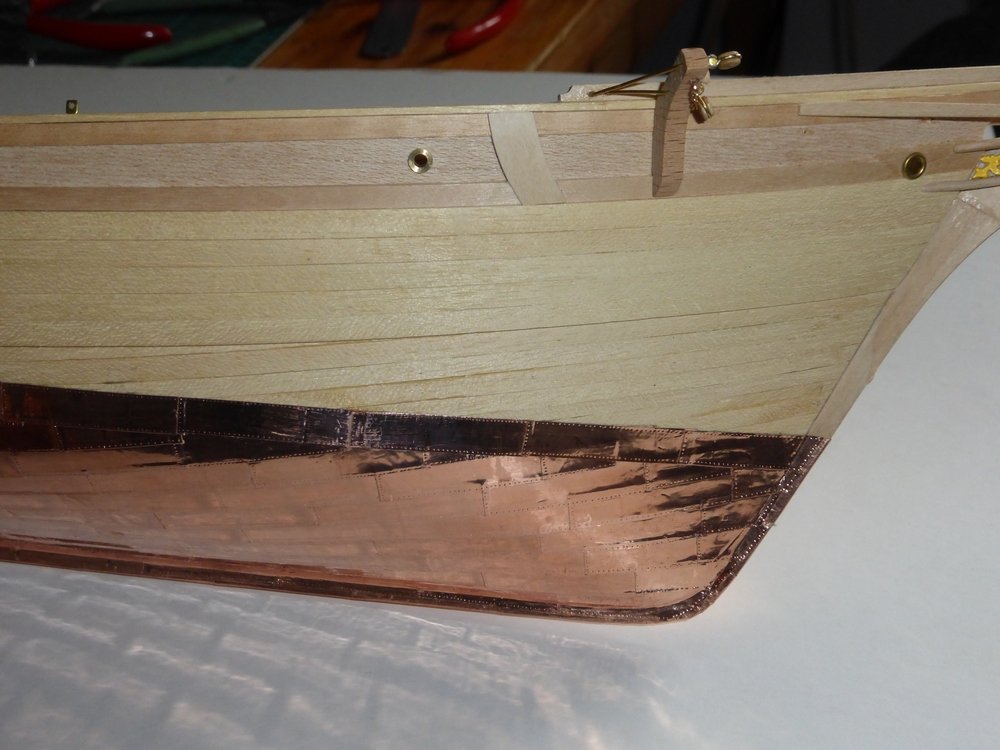
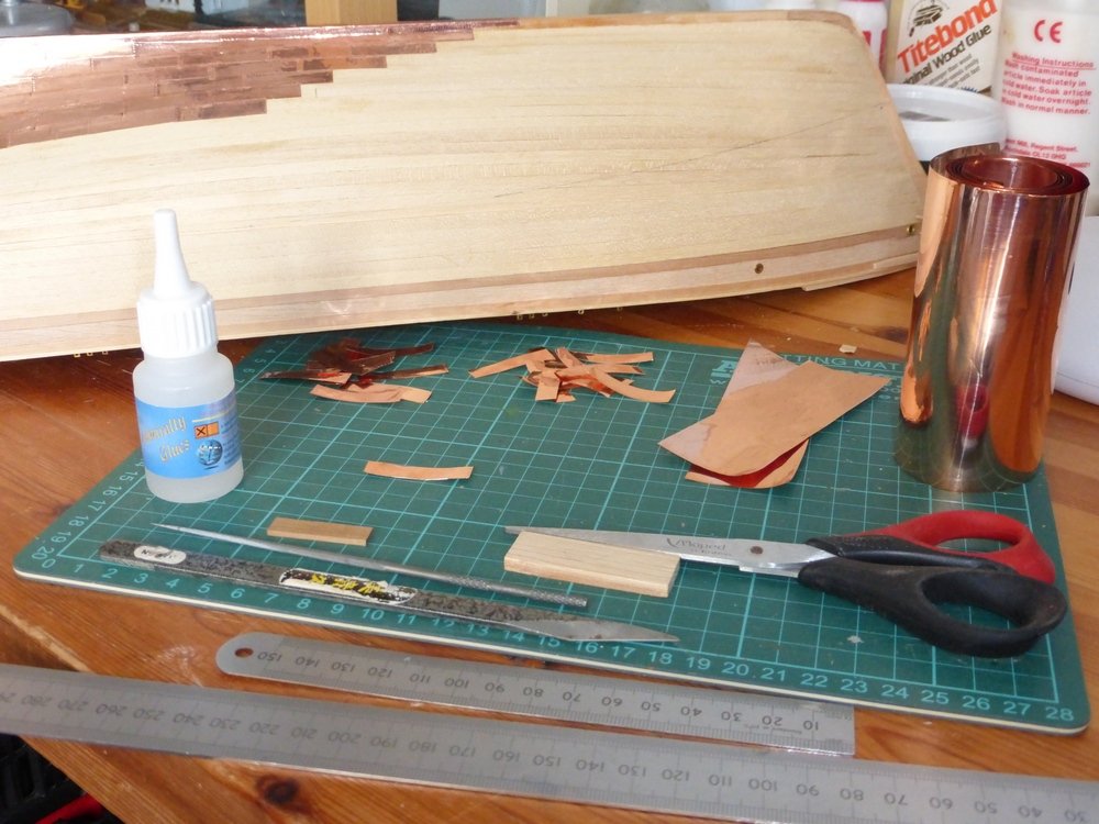
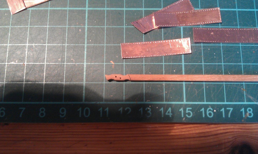
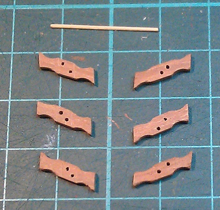
Coppering the hull. It has been some time since my last update as I have started coppering the hull. Something I have not done before and felt I could not put off any longer. I first read all I could find on MSW on the subject. Unfortunately most of this did not relate to what to do with a 1m role of 100mm wide copper strip which is 0.05mm thick (2 thou). My guides for this are the plans from Musées de la Marine and the picture below. From this I decided that the copper plates on the model should be 35mm x 8mm. Working on my principal of using as much material as supplied in the kit as possible I started cutting the supplied sheet into the required plates. Once I had a few to work with I started trying out different patterns of indentations to represent the tacks that these are held on with. I finally settled on doing each plate by hand using the end of a sharp needle file to make each indentation at a spacing of about 1mm. I would put these along two sides and overlap the plates. Also these would be glued in place using CA adhesive. It has occurred to me that as this ship was launched in 1932 and has been re-coppered fairly recently, the copper plates may not be attached in the same way as on a warship 200 years ago. However lacking any information on this I have proceeded in the assumption that they are still nailed in place. This picture shows. In more detail, some of the plates prepared for the top band with rows of indentations on 3 sides. Below that is a cleat I am making. This goes on the bulwark stanchions, see later. The next picture shows the stages of assembly, starting with a roll of copper strip, then cutting off 35mm lengths which are then cut into 8mm slices. These then have the nails embossed and are then stuck to the hull. All the tools I am using for this are also shown. The first problem was plating around the propeller aperture which required many small plates cut specially to shape. This took a long time and I was not very happy with the way it looked close up. But from a distance, at least it covered everything. I did not think I would achieve much by pulling it all off and starting again. It might have been better to leave this to later when I have had some more practice, but as I am overlapping the planks it is where I have to start. It was then fairly straight forward doing most of the rest of the plating on the first side. Though difficult not to get CA glue over everything, especially my fingers. I lost the line onece or twice but it is not too obvious. The main problem was I had to finish with a 2mm wide row before putting on the top band. My original plan had not included this. My overlap must have been a bit more than planned. There are 10 rows beneath this, so that is only 0.2mm extra overlap for each row. For the second side I thought I would try a different method of gluing. At this point I have just started and am using some double sided tape I have. This is very sticky and holds very well. It seems ideal for the majority of panels that are flat, but does not work well with any that need to be bent, for instance those at the bow and along the keel. I am still using CA adhesive there. The problem is that using the double sided tape there is no movement possible. Each plate needs to be in the right place first time. I find in places like the bow and the keel I need some movement available to get the plate exactly where I want it. As altogether there are about 400 plates, ignoring those around the propeller aperture, I am occasionally taking time out of the plating to do a few small jobs. I have added most of the points where rigging is attached to the poop deck. I have installed the chain plates, this picture shows those for the main mast. I spent a long time deliberating where these went and eventually decided they must be fitted to the inside of the bulwarks. The first 3 hidden by stanchions. Then I made these cleats, which are used to secure the sheets from the fore sails. Their positioning can be seen on the following picture of the real ship. Those supplied in the kit are small plastic things that look nothing like this. I will probably end up using some of the ones supplied, but not here when it is easy to make replacements. I will post another update when I have finished the coppering. Glenn
- 101 replies
-
- 11
-
-
- L Toile
- Billing Boats
- (and 1 more)
-
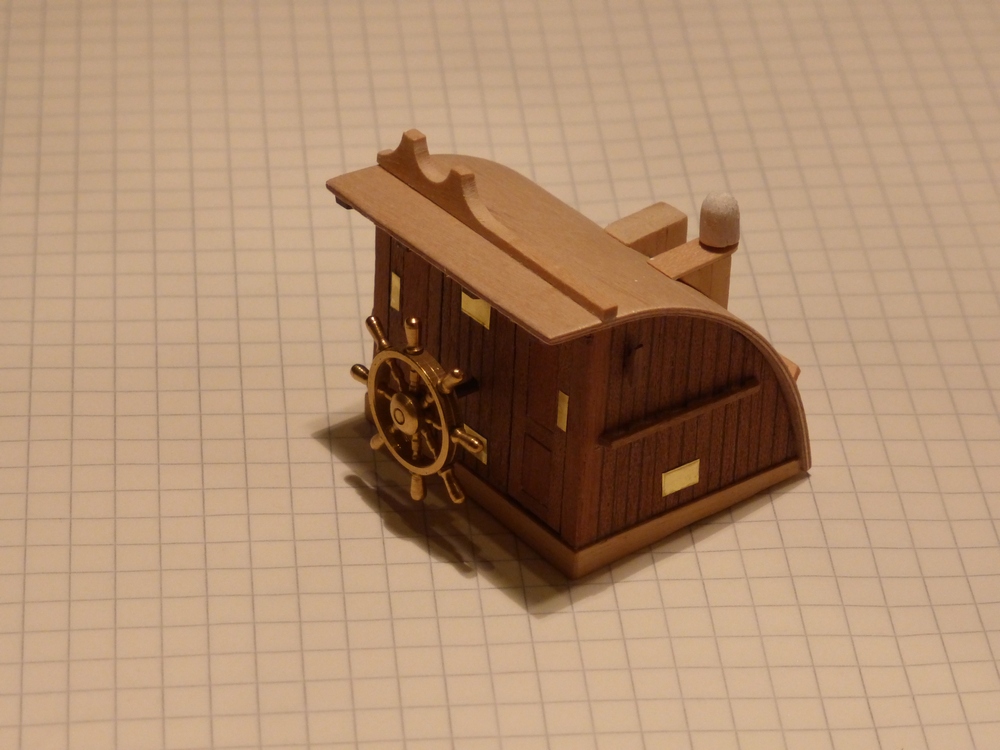
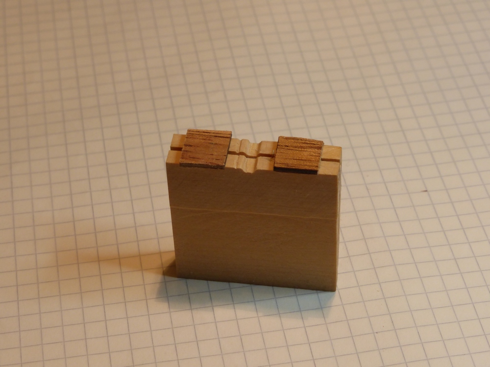
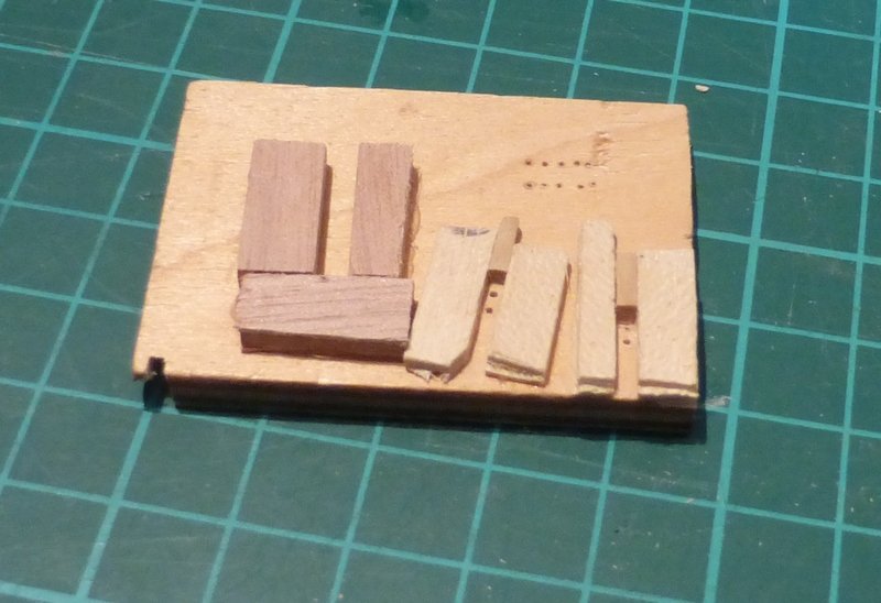
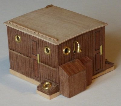
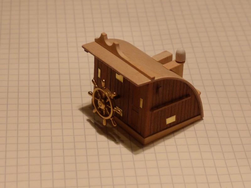
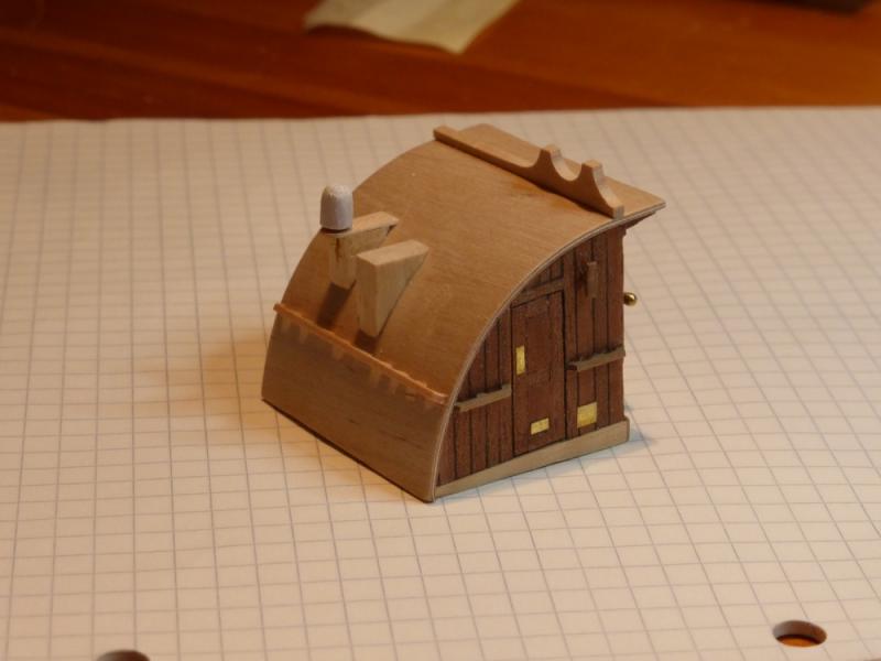
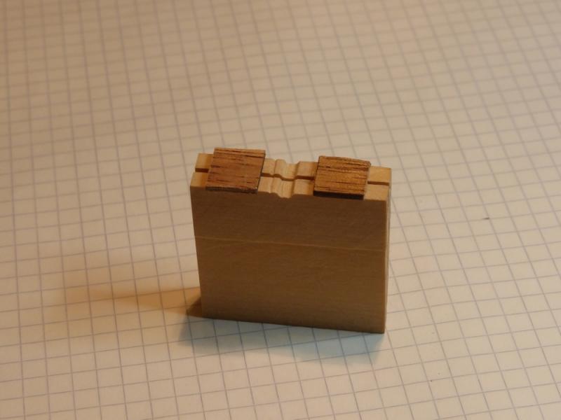
A brief update as I have finished my first sub assembly; the rear cabin. The following pictures are taken on 5mm graph paper. The pictures of this in my last post convinced me that it did not look to bad, so I went back to it and completed it. The most difficult part was doing those slotted rails, even with the jig I made (see below). The dark ones are walnut and the light one is lime. These are difficult in the walnut as the small pips keep falling off. It is much easier and quicker to make these in lime. If this continues I may end up making all further strips in lime and staining them where required. After failing to satisfactorily make these previously, this time a first built a jig. This has a slot for the wood strip and a profile for the wood to be removed. It then has a small notch which acts as a marker for the amount to move the strip on before cutting out the next notch. After cutting the first few notches I realised I needed something to stop the wood lifting as I cut the bottom. Hence the two pieces glued on top. I also found this made it much more difficult to push the strips through and hence there was less risk of them moving while making each notch. It's now time to get back to the hull and finish that. Glenn
- 101 replies
-
- 8
-
-
- L Toile
- Billing Boats
- (and 1 more)
-
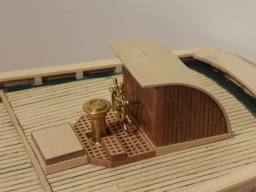
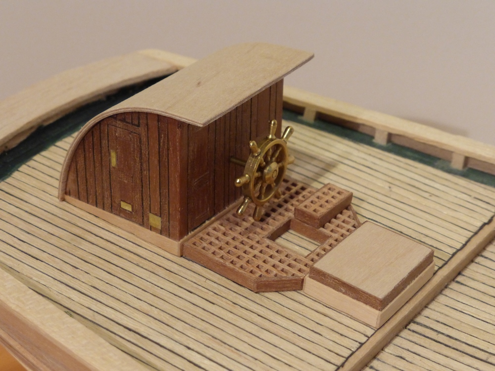
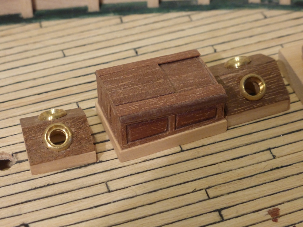
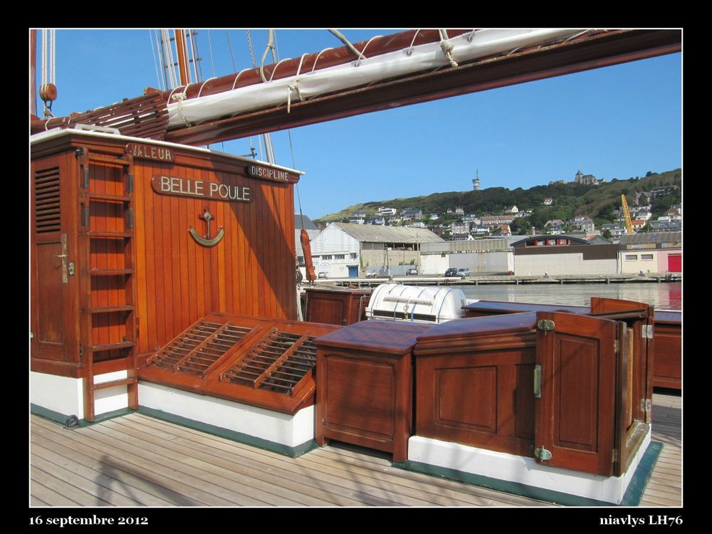
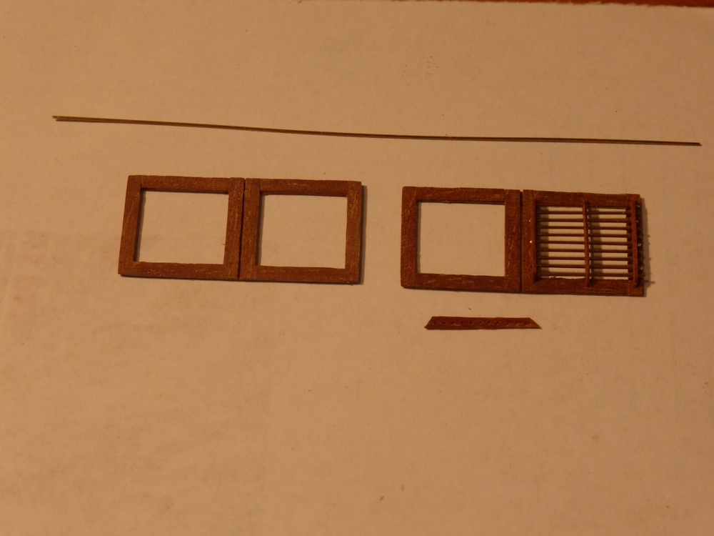
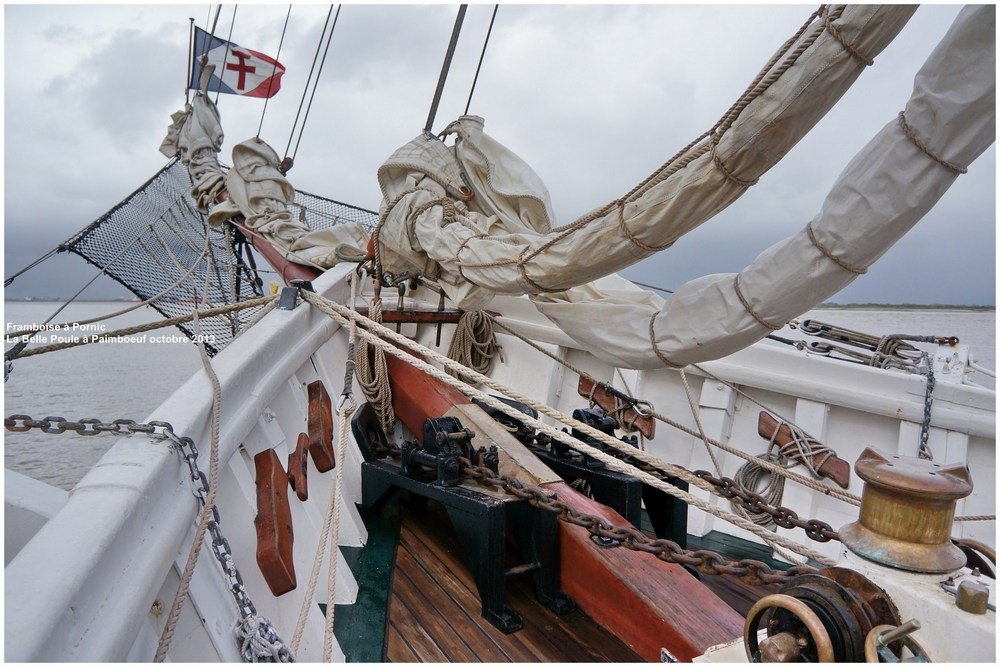
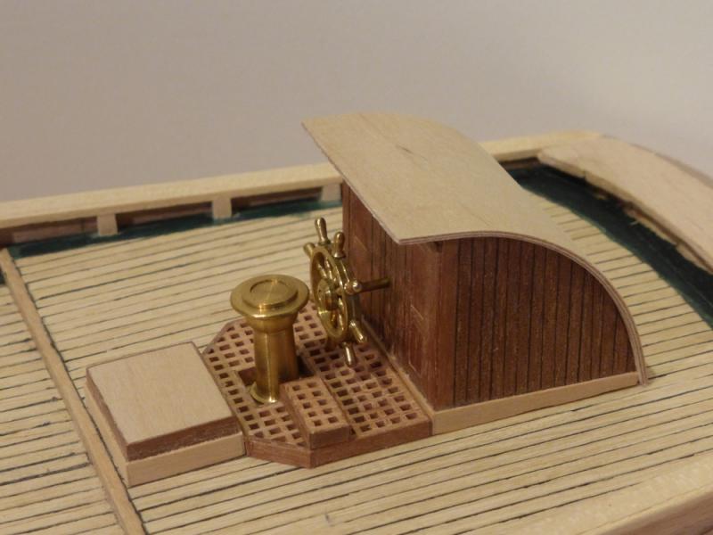
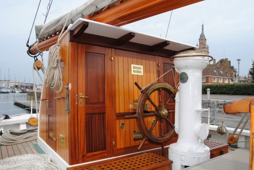
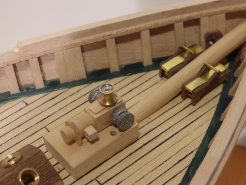
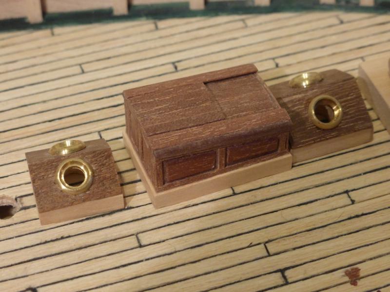
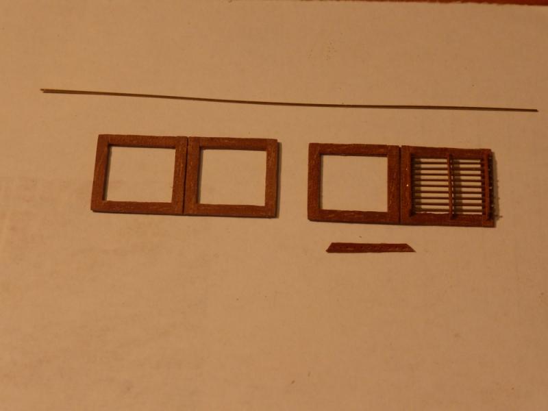
Since my last post I have received the plans I ordered. They are of very high quality and come with an 8 page booklet about the ship and how to build a model. Unfortunately it is in French so very difficult for me to understand. Deck fittings First a few pictures of the aft cabin, which I now know contains the radio room, the wheel house and the ‘Armoire à Pavillons’. Not sure about this last one, possibly the flag locker. This is not finished and none of this is glued in place, but there is not too much work left. The reason I stopped was that I was not sure about the brass fittings I was making to represent the door finger plate and air vents. Under a x10 eyeglass they do not look very good, but I am happy with how they look in this photograph so I will continue. I believe the Dusek model has photo etched parts (long sigh). That pedestal in front of the wheel is the compass. The box in front of that is the ‘Panneau de cambuse’. I guess that means it’s a storage box. Next a review of the deck fittings at the bow. I do not have a single picture that shows the real ship, just a bunch of them that all show parts. So I will just show the following pictures of the model. Again none of this is glued in place yet. First nearest the bow, each side of the bowsprite are the chain stoppers, then comes the electric chain winch. All these were scratch built. I have made some brass plates, one end of which wraps round the brass rod on top of the chain stoppers and the other end has a slot for the chain. When in position these actually work and prevent the chain running out, while still allowing it to be pulled in. However I have taken them off because I keep playing with them and bending them. On the chain winch, I used what was meant to be a dark metal paint to paint the chain wheels (or whatever they should be called) however they came out looking awful. They were turned from dowel using a drill and files. I will repaint these too look better and paint the rest white. Then a power cable is required which runs from the skylight behind to that box on the side of the electric motor. After this is a skylight, the forward companionway hood and another skylight. The two skylights are as per the kit except that the dark plastic covers have been replaced by new ones made from walnut. The companion way hood is again made from scratch in an attempt to make it look like it does in the pictures. This one is a slightly smaller one than the main one as shown in the next picture. That is about how far I have now got. I am currently making the ‘Grand clare-voie milieu du poste élèves’. I do not know what that translates as but it is a large skylight just aft of the fore cabin. Shown here in this picture of the Belle-Poule. I have made the lower part which is just a box and am now making the ‘windows’, of which there are two each side which can be opened independently. As I cannot make working hinges at this scale, mine will remain closed and hence I have made them as one piece each side. I am currently fitting the protective bars. These are from 0.45mm brass rod and are spaced about 1.35mm between centres. Once glued I will trim them to length. I then have to glaze them. I can use some plastic sheet I have, but I am not sure if I should try some of those thin glass plates used for making slides; of which I have a lot. Or is this asking for trouble as it will break sometime in the future. They are 0.1mm thick. The difficult part here is making the strips with holes spaced to take the brass rod. I only have my Dremel drill press. I make the strips using a jig as shown below: Everything is clean and firmly tightened. Also with a 0.5mm drill bit, it is mounted with only a short amount showing. Then a right angle piece of wood is clamped to the drill stand and the piece of wood to be drilled is stuck to a carrier with double sided tape. This is positioned such that the first hole to be drilled is in place when the carrier is in the corner. Then the drill is switched on and the first hole drilled, then a piece of wood is inserted between the carrier and the side of the right angle frame and the carrier pressed firmly up to it. Then the next hole is drilled. This process is then repeated until all required holes have been drilled. Taking care to drill each hole in the same way every time. Only once all holes have been drilled is the drill switched off. To drill a second row I then remove all pieces from the end and add a piece of the required thickness at the front. Then repeat the above process. When they are this small and close, like this, I find about 2 in every 3 are useable. Glenn


- 101 replies
-
- 10
-
-
- L Toile
- Billing Boats
- (and 1 more)