


BenF89
-
Posts
316 -
Joined
-
Last visited
Content Type
Profiles
Forums
Gallery
Events
Posts posted by BenF89
-
-
Titanic had a similar arrangement, with maybe one or two aux winches per side to recover boats. There were 8 boat stations per side, in groups of 4, one fwd and one aft. So, figure 1 winch per quarter (fwd port, stbd aft, etc) would serve, through block and tackle, four boats. If there was only one winch per side, as in the KWdG, then eight boats each.
(Another interesting point - KWdG had more boat stations than Titanic, but I suspect Titanic was a fair bit larger in capacity. Titanic did have 20 boats, but four were canvas sided collapsibles. One stored inboard of each of the forward most stations, and two were stored on the roof of the officer's quarters, adjacent the the forward most stations. By the time the collapsibles on the roof were employed by the crew during the sinking, they had trouble freeing them, and then could barely get them attached to falls, which was a moot point anyway, as the starboard collapsible swamped and floated away as the boat deck submerged, and the port one actually fell off the roof upside down, and floated away upside down. People ended up climbing on it as a sort of raft.)
-
Bob,
Just catching up after some busy time away from MSW - the Pequot looks great! That's a neat trick you learned for the vents- thanks for the tutorial.
She certainly has that mid-century feel to her - very classic looking. Can't wait to see the details come together! And, I know what you mean about pictures. I have to discipline myself to take them, else I would get in the groove and skip a whole bunch.
- mtaylor, Canute, Mirabell61 and 2 others
-
 5
5
-
Nils,
Not sure if I've ever commented here before, but I wanted to say I've caught up with this log after several months of not stopping by, and the progress you've made is fantastic.
I noticed back in March you had a curiosity about some winches on the boat deck. I was hoping to offer some insight by reviewing the information I had available on the Titanic. But, alas, the winches she had on the boat deck for recovering lifeboats were oriented athwartship. That said, I agree with what had been previously suggested regarding their use as a multi-purpose auxiliary. In any event, they are fantastic, as is everything else.
Looking forward to continuing to follow along!
- Omega1234, Piet, Mirabell61 and 2 others
-
5
-
OK! Back at it. It's been a LOOOOOONNNNNNGGG time, but a lot has transpired. I spent months studying, took my exam in April, and then toward the end of May, found out that I passed! So, I am now a licensed Professional Engineer in Naval Architecture/Marine Engineering in the State of Washington. We've also been very busy in our garden - I've built most of a fence (still one section to go), and of course there's the ins and outs of gardening. Watering, weeding, harvesting, etc.
Plus, I was stuck in a bit of a rut with the boat, not quite knowing where to go with the actual outfit of the hull. I had vague ideas bouncing around, and a vision of the final product, but no clear plan on how to get there.
But, I finally figured it out! I used some templates of the overall deck plan, profile, and body plan from WAAAYYYY back when I was checking my lines drawing, and used them to peg the length, width, and a guess at the shape of the deck at the level I want it. Then, I kept hacking at it until I got it mostly right. I retraced the hacked up piece, re-faired it, and re-checked the shape, and it still mostly fit.

Initial, Hacked Up Lower Deck Template
So, I have a deck shape. This was a key to making a lot of things fall into place. But that will be a post for tomorrow.
More to follow...
-
-
Hi Patrick,
Absolutely wonderful to see your progress - had to do a 'binge' catch-up again, as I've been neglecting MSW updates for a while.
I'm hoping to get back to the Doll Boat soon. I've been busy with outdoors stuff and work stuff, plus a bit of a problem-solving slump. Lots of staring and head scratching, but not much of a plan yet...
Take care!
-
-
-
Hey Patrick!
It's been a while since I caught up - things are looking excellent. The last set of pictures is a good indicator of how great this boat is going to turn out once finished - seeing her 'sisters' all together my honest first impression was a reminder of how great they all turned out. High, high quality work!
Good luck on continuing to get the exterior fit and finish you're looking for!
-
-
Why do they have to alter boats? I forgot the boat I am building is the boat pictured in the first entry of this thread. That was before the hull was modified. I’m sure glad I didn’t already make that change. But I still think it was an interesting modification and wonder why.
Bob
The sarcastic answer is that they alter boats to keep the Naval Architects busy trying to catch up. Actually a prominent issue with fishing boats:
Fishing boat operator: "Hey, Naval Architect, I just added 3 Long Tons of gear to the top of the mast. But I'm still good to load up all the fish I want, right?"
Naval Architect: "What?! Why would you do that? That raises your center of gravity 3 inches, and you barely passed your intact stability requirements before. Ok, let me do another week's worth of troubleshooting to develop a new loading plan...."
Fishing boat operator: "But we need to leave tomorrow!"
This isn't a specific example, but it's not too much of an exaggeration either...
P.S. - the boat is looking great!
-
Sorry for the lag since the last post. I had done a little work a while back, but was trying to wait to do a little more before posting an update. But, I've been delayed for a variety of reasons. So, I decided to just make a small post updating what I did a few weeks back.
FINISHING THE PORT SIDE
So, I did the minor amount of work needed to get all the pieces on the port side of the engine - the air intake hose for the air filter (which isn't so much the port side as it is the aft end), and the exhaust mixer/outlet.
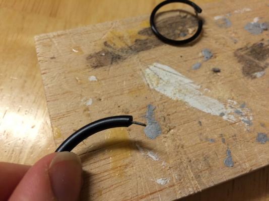
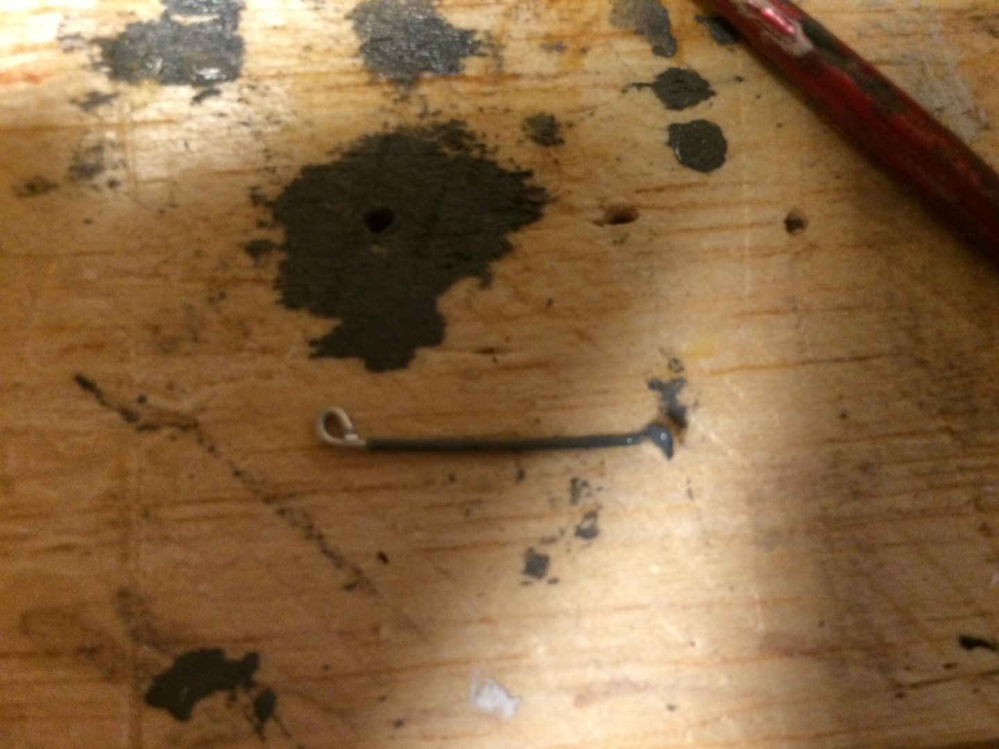
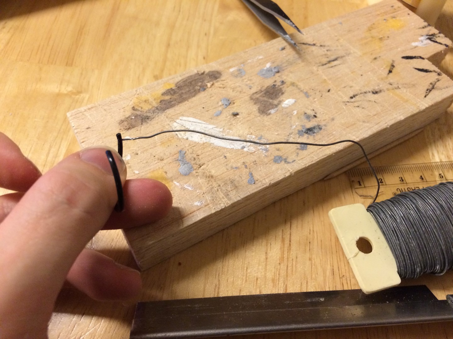
The air intake hose was fairly easy; I just drove a pin into the end of a section of O-ring, and then bent the rigid part at 90 degrees.

Air Intake Hose
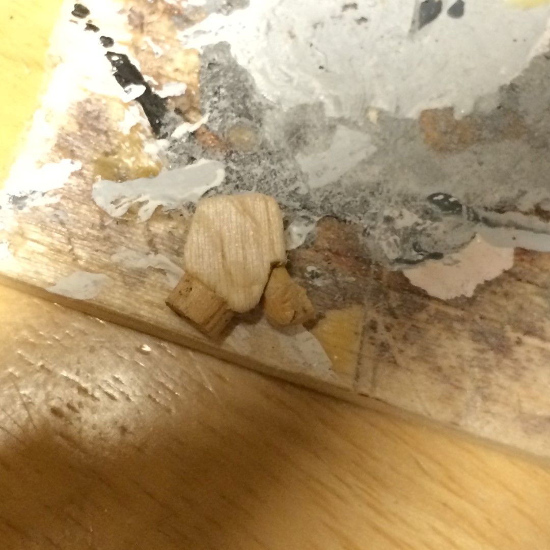
The exhaust manifold was a little tricker, but not much. I found a balsa plank that closely matched the thickness, and then just took measurements off the model and translated them to the plank (using my metric ruler this time, so there were no compounding conversion errors. Better late than never I suppose....). I picked a dowel that closely matched the outlet diameter, and glued it on to the end.
Exhaust Mixer Assembly In-Progress
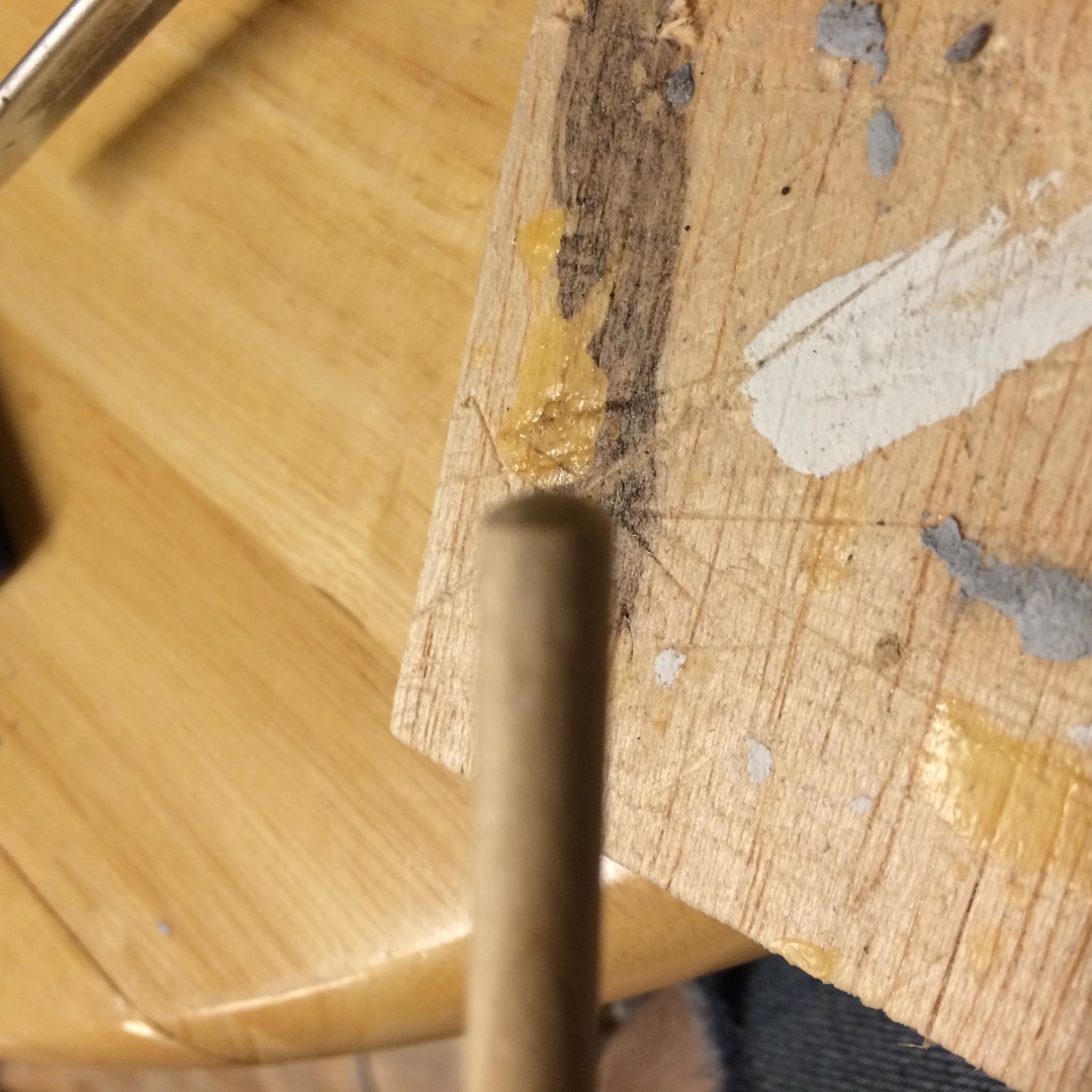
I then found a smaller diameter dowel to use for the 90 degree bend coming out of the exhaust manifold. This was one of the trickiest parts on the whole engine, since, you know, dowels are straight and not prone to sharp bends. So I used a trick I learned from Dennis on his Andrea Gail build, when he made goose neck vents. I cut a section of dowel at (roughly) 45 degrees, and then another. I glued them together 45-to-45, so that it made a hard-cornered 90 degree bend in the dowel. Then I, to the best of my capability, sanded the corner to make it more of a smooth curve. It's not perfect, but it got the right impression, which as you should all know by now is my primary motive.

Mixer with Rough 90-Degree Elbow on bottom
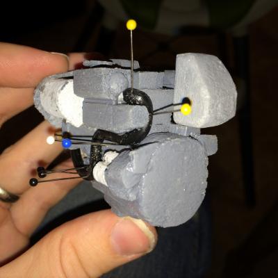
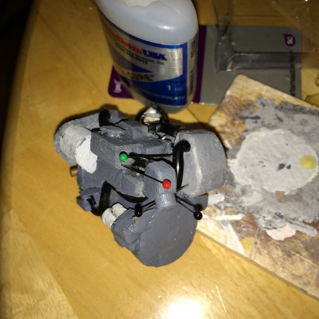
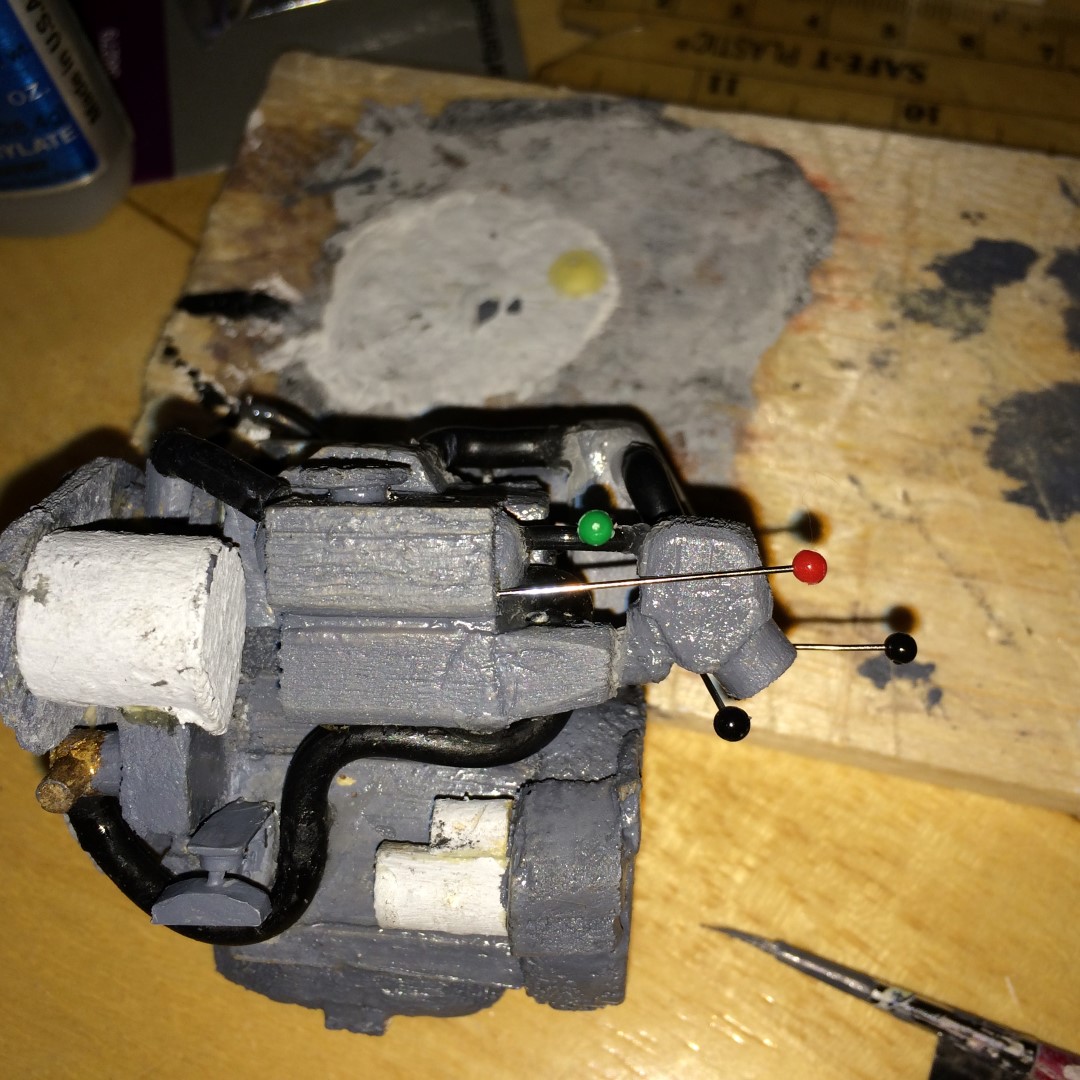
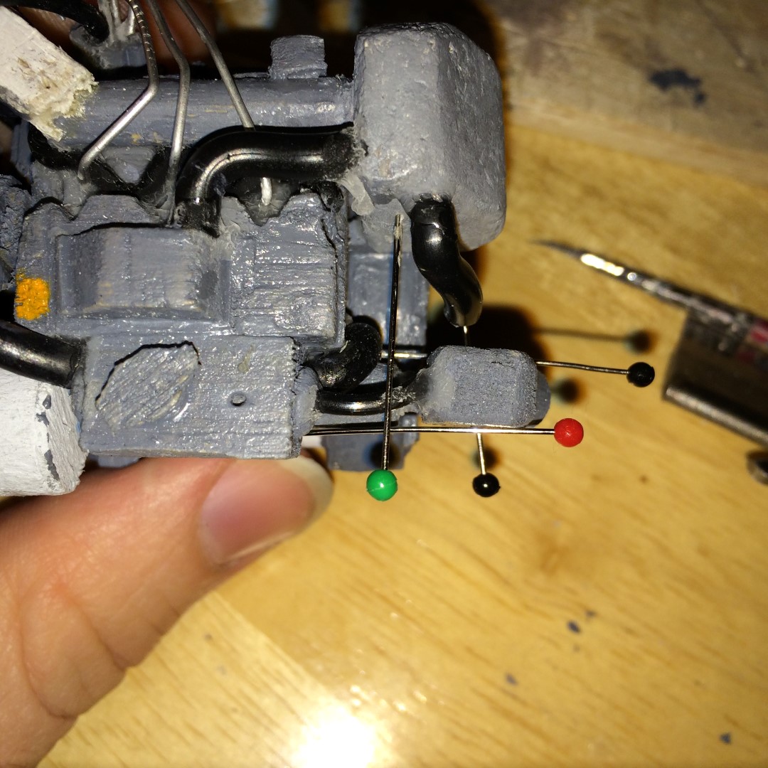
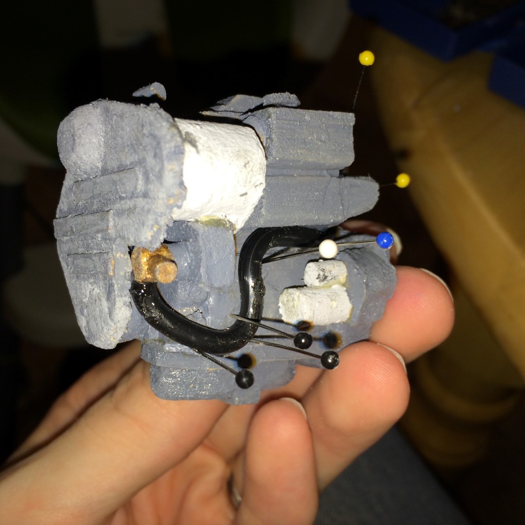
The final annoying aspect was attaching the seawater hose coming out of the coolant heat exchanger. This makes some severe bends since the mixer and heat exchanger aren't in the same plane transversely, but are fairly close together longitudinally. It took a lot of super glue and patience to get it to stay in the right place and shape. And involved some, perhaps overkill, pinning of the hose and mixer so nothing moved as the glue set (since the hose was wanting to push the mixer away, or twist it, or anything to dump the strain of the sever bends.)

Gluing the Seawater Hose 1

Gluing the Seawater Hose 2

Gluing the Seawater Hose 3
So, the next step is to plan out the assembly of the saildrive gear that attaches to the aft end. And, of course, how to build the interior of the rest of the boat.
Unfortunately, it is going to get harder for me to make time to work on this for a while. I have started studying to sit for my Professional Engineering license exam in Naval Architecture coming up in April (assuming my application is accepted). And boy, do I have a lot to brush up on. Fortunately, I am taking a review course offered through a professional society called SNAME (Society of Naval Architects and Marine Engineers), so it isn't me haphazardly trying to figure out what's important. But, the review course comes with homework, and since it all has to be done with a basic calculator (no computers), it takes a while to do some of the calculations.
All this means that the several nights a week I would normally use to work on the model, I'll be using to do homework and study. It's a good use of the time, but admittedly means that progress here will be slow. Just a heads up.
On a related note, it's seeming like the deadlines I imposed on myself to get this done are going to be less achievable
 We'll see how complicated the interior ends up being, since at this stage I'd like to keep it basic enough to be played with 3-4 year old style. (The engine is my little detail pet project, that will be fairly well protected once it's in the engine compartment, which will be hard to get into.)
 -
-
Wow Patrick, looking great!
And, I wouldn't worry about sporadic decisions and inconsistencies in your build sequence - custom yachts always seem to cost more and take more time than originally planned anyway - what with the owner making last minute design decision changes and such.
On time and on budget are the mystical, lofty dreams that designers and shipyards of any type of boat have heard legends about, but rarely see happen in real life (unless you're building a product line of cookie-cutter boats or ships. Even then, the first boat will take longer and cost more than the tenth...). But yachts and government programs seem to be the worst, since the pockets of both of those types of owners are fairly deep, and the people who make real decisions for either generally don't know jack squat about things like competing or contradictory requirements. It can get fun.
My favorite example was a spec that wanted a 70-80 foot (21-24 meter) boat that could go 40 knots carrying a main battle tank while only drawing two feet (0.6 meters) of water. And they wanted it to be able to survive Sea State 5 (8-13 ft/ 2.5-4 meter waves), while carrying a main battle tank and drawing 2 feet of water. Uh-huh.
But, I digress. I think your build is coming along fantastic, and as long as you don't do something so out of sequence it makes another job really really difficult, there's no problem jumping around. From what I've seen, build sequences and sometimes even construction drawings are treated like the Pirate's Code - more like guidelines, than actual rules.

-
Today I have a small but significant update.
COMPLETING THE STBD SIDE
Yup, that's right, after the small amount of work I did in this update, I am calling the starboard side of the engine done!
I started by making the dipstick pipe to the lube oil sump, and some other doohickey gizmo that I can't even make up a name for because I have no idea what it's for (I didn't take a picture of it, specifically, but I'll point it out in a later one below).
0.20" Rod Bent To Shape and Painted to Simulate Dipstick
Next, I ran a small section of hose the runs from the lube oil cooler to a fitting on the crank case. In the picture, if you look immediately above the pin, there is a cylinder sticking out of the case with another cylinder vertical on top. That's the doohickey gizmo I was talking about.
Hose Added and Pinned
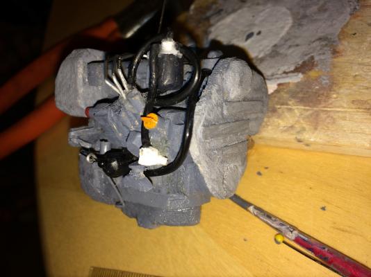
Finally, I added the large diameter hose running from the air filter to the top of the crank case. This was a PAIN to install, even though it is relatively simple. Because it takes a sharp 90 at the end, but is otherwise straight, I had to run a pin into the end to give it enough rigidity to stay straight up to the bend. Then, I had to try to glue it to the filter and let that set enough to bend the other end, since there wasn't really anywhere to pin the hose directly to the top of the engine. And, forcing the tight bend with hardly any support was frustrating - it took a few tries until I finally got to a point I could pin it in place and glue.
Air Filter Hose Added
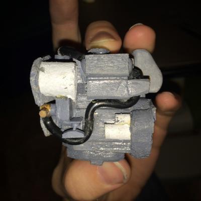
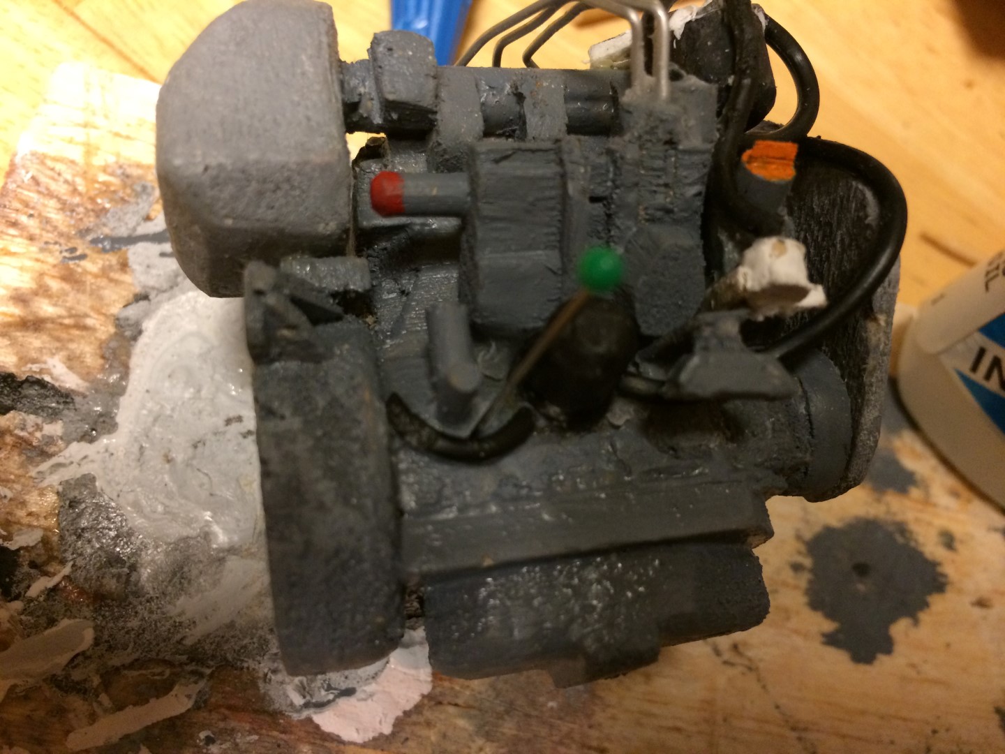
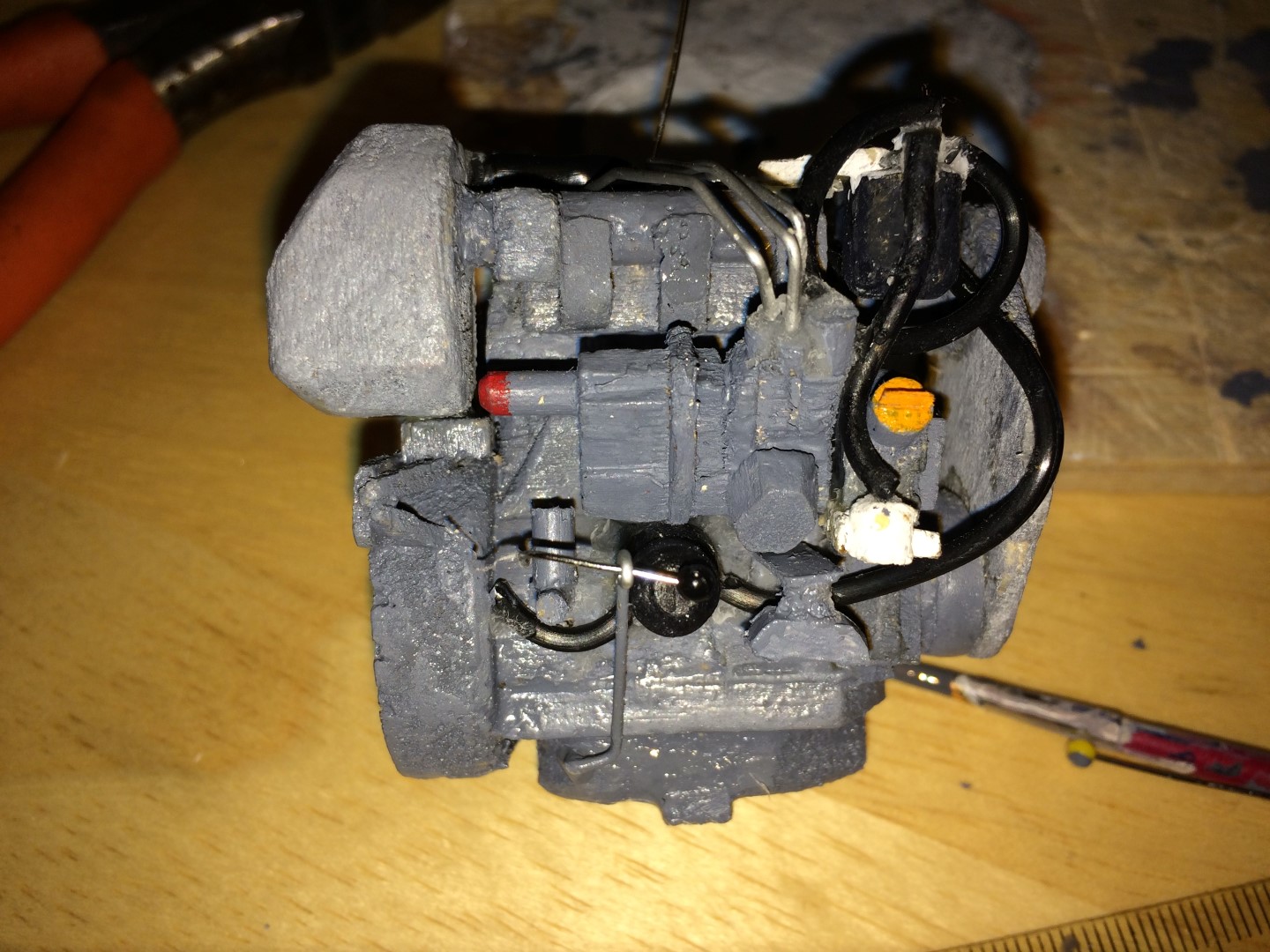
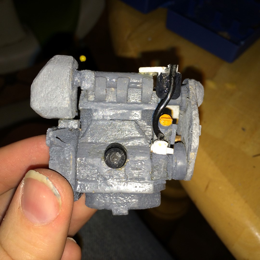
So, here are some shots of what I am considering the completed starboard side. I may touch some paint up here and there, but otherwise, all the features are in place.
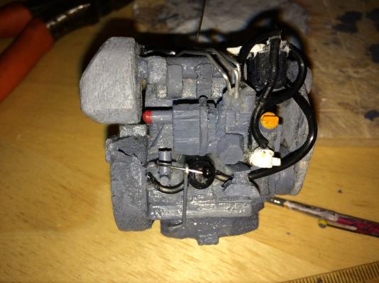
Engine Stbd Side - 1
Engine Stbd Side - 2
Port side just needs the exhaust mixer, and the aft end needs a hose for the air intake. Then onto the gear for the sail drive!
-
Thanks everyone for the likes and comments - I hope you all had a good Christmas and are looking forward to the New Year!
I made some progress on the model a few weeks back, but haven't found/made the opportunity to update the log until now.
INJECTORS AND FUEL RETURN
The first update I did was to make some small pieces to stand in for the injectors. The primary purpose for these parts was to act as a guide for running the fuel return line.
Fuel Injectors Added
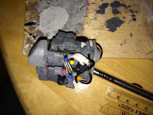
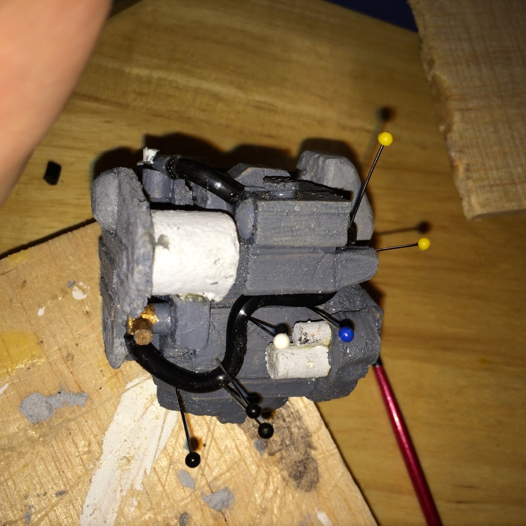
Then I ran the fuel return line. I needed the injector squares to help me place the twists this line takes- it snakes along the top of the engine, probably to provide surface area for cooling the fuel down on its return to the pump. Maybe. My memory of diesel engine operation is a little fuzzy. Anyway, it was a pain to install, even with fairly flexible small thickness o-ring. They are some TIGHT bends at this scale.
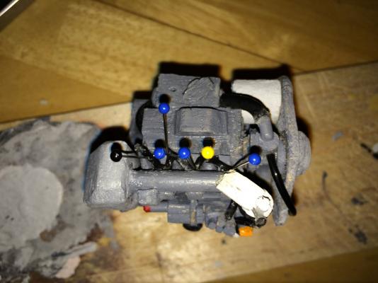
Cacophony of Pins Needed To Force The Shape of the Fuel Return Line
Fuel Injector Lines
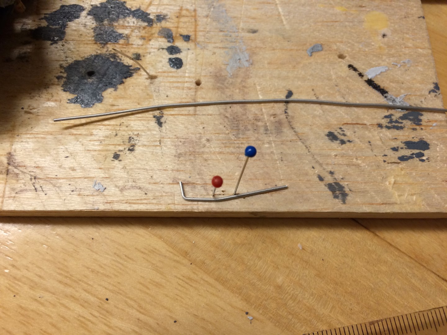
Next, I started on a task that I've been both anticipating and dreading - forming the fuel injection lines themselves. These are fairly prominent on the engine, and have some really complex three dimensional bends. I made these from some 0.20" aluminum rod. At first, I set up a nifty way to make the bends in a 2D plane. I would then eyeball the bends in the second direction to form the total shape. I basically just used a balsa block, some pins, and a metric ruler. The 3D computer model I use is in metric, and with these it was more precise to just take the metric measurement from the model and use that, rather than convert to inches and then round to the nearest 1/16th or 1/32nd. Yeah, yeah, with a metric ruler I could have done that for the whole build. More on that in a second....
Placing Pins

Placing Rod for Another Bend

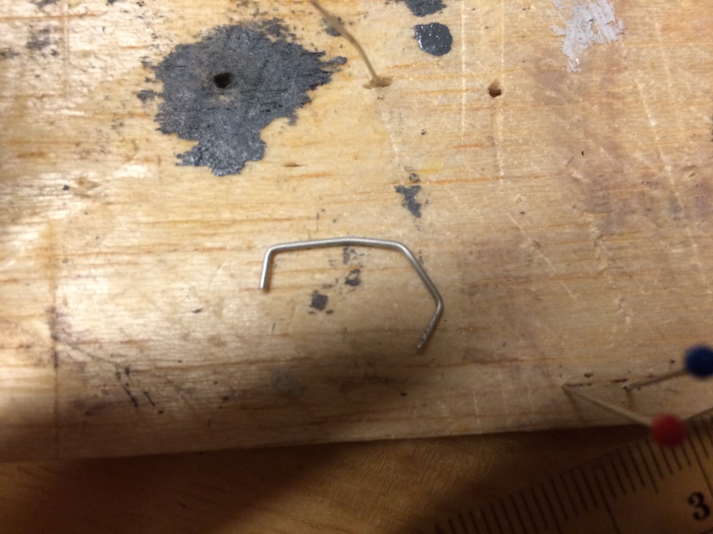
Completed First Injector Line
I was super happy with the way the jig worked, and the final product looked right compared with the 3D model and photos of the engine. And then I tried to put it on. Well, that whole 'looks about right' mentality, and 'round to the nearest 1/16th' precision led to an injector-to-fuel-pump-length that was a weensy bit greater than what it should have been at true scale. So my precise method of measuring distances between bends and then jigging pins to make the precise shapes went out the window. With that method gone, I fell back on what I've sort of been doing the whole time - I winged it and tweaked the lengths and bends of the first line until it was mostly right, copied the other two off that one initially, then tweaked them until they looked right, too.
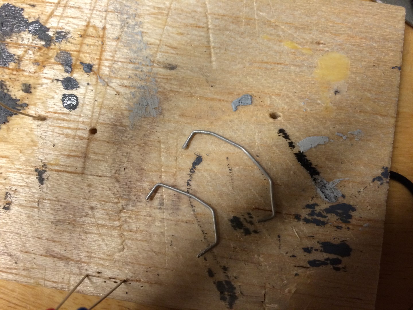
The last line had the most severe amount of three dimensional shape, so I ended up doing that one like three times. But, in the end, I'm 83% happy with them. I could have kept tweaking and perfecting, but I had to limit myself and move on, since, you know, I have to build the whole BOAT this thing goes in at some point.

Original Injector Line (Smaller One) vs Adjusted Injector Line (Larger One)
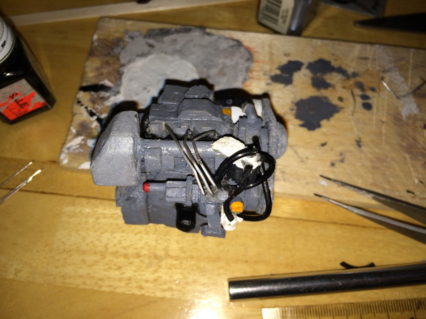
All Injector Lines Glued On, With Pins Supporting Position
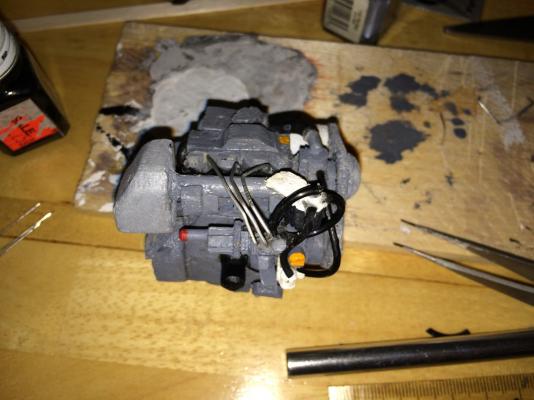
Glue Set and Pins Removed
I did tweak the lines one last time, as I was forlornly staring at the not-quite-rightness of them, and now I am 92.4 % happy with them.
Also, I did manage to break the engine once or twice, and drop it at least once, while trying to get the fuel return line on, and then the injectors. It was intense. All was repaired, though, and I won't tell you what broke because you probably can't tell anyway.
And, on top of the major tasks I outlined here, I also did some more hose-running work. I added some hoses from the fuel filter to the injection pump, and ran a line from the coolant pump to the lube oil filter. I didn't take in-process pics of these specifically, but you can see them in the others.
Again, hope everyone had a Merry Christmas, and and I wish you all the best for the New Year.
- popeye the sailor, mtaylor, dgbot and 3 others
-
6
-
Wow, Patrick, looking really great!
She's looking very sleek and elegant. And it's good to see your thought process teasing out how to get the functionality you're looking for!
And, I especially love the shot your son took of your workstation - really puts things in perspective, and also gives a 'behind the scenes' feel with the various drawings and tools lying about.
Glad to hear you had a good Christmas, and all the best for the New Year!
- Piet, GLakie, Dimitris71 and 4 others
-
7
-
-
Michael - this has given me some vague idea of how to accomplish some items I was having trouble visualizing how to do on my project! Thanks a lot!
And Patrick - is there any centralized stairway, or other vertical shaft/causeway (elevator or ventilation, etc) that you can discern? These would be good candidates for centralized 'pillars' that can stay fixed to the main hull assembly, while the decks slide over them. Then, if you have say, two of these vertical causeways you can use, that will fix the decks in rotation and translation, allowing the only free movement to be vertical. I can draw up a sketch to clarify if you need. The only trouble I see with this idea might be scale - the size of any vertical causeway, to scale, may not be structurally sound enough to act in the way proposed. It truly is an interesting challenge...
- Dimitris71, GLakie, michael mott and 2 others
-
5
-
Having done mooring cleat sizing for even just an 85 foot boat, I have to say those must be some HEFTY bulwarks! Properly sized and designed cleats carry a LOT of load in them. Have you seen any photos of the boat that confirm the plans, or provide more clarity into how the arrangement might have been used?
- mtaylor, Omega1234 and Dimitris71
-
3
-
-
Looking good! Always fun to see the long periods of preparation culminate in actually building something.
- Old Collingwood, mtaylor and Canute
-
3
-
Hi Patrick and Mark and all who have 'liked' my posts!
Thanks for the kind comments and encouragement. Fiddly is the exact right word. Again, I have even more appreciation for what Patrick accomplishes. I took a look at my engine, and realized that as small as it is, it's at least half the size of the entire boats he builds. Putting bulkheads and joinery in the hull of my sailboat is going to be cake compared to this. I suppose it's good skill building, so the rest of the build will breeze right along (yeah, yeah - famous last words
 )
)Well - I got yet another evening to do some work on the model, and I actually got that fuel injection pump done. It helped that we don't have printer paper at home, so I had to print anything I wanted before I took off from work Friday, and the only thing I took was the info needed for the fuel pump.
ENGINE FUEL INJECTION PUMP
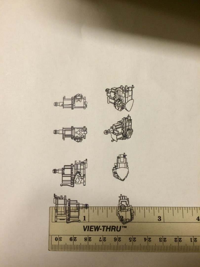
First, a shot of the plan sheet, with an imperial/metric ruler for scale. The whole assembly is an inch long.

Fuel Injection Pump Plan
So, the first thing I did was, similar to the other complex assemblies thus far, look at components pieces. There's a long cylinder, then blocky part, then a dividing plate, then another blocky part with some vertical grooves that has a blocky part sticking out the side, and some cylinders at the top. Note these are all incredibly technical terms that demonstrate my thorough understanding of the intricate assembly that is the injection pump (
 ).
).(I was able to identify the first long cylinder as the emergency stop, and some of the fixtures on the top of the last blocky part as feeds to the injector lines, feeds from the fuel filter, and a connection for the return line from the injectors. Since there doesn't appear to be an engine computer on this model, I assume it's mechanically timed with the belt and a cam shaft or something. So there's probably a cam-driven gearing mechanism to precisely time the injections.)
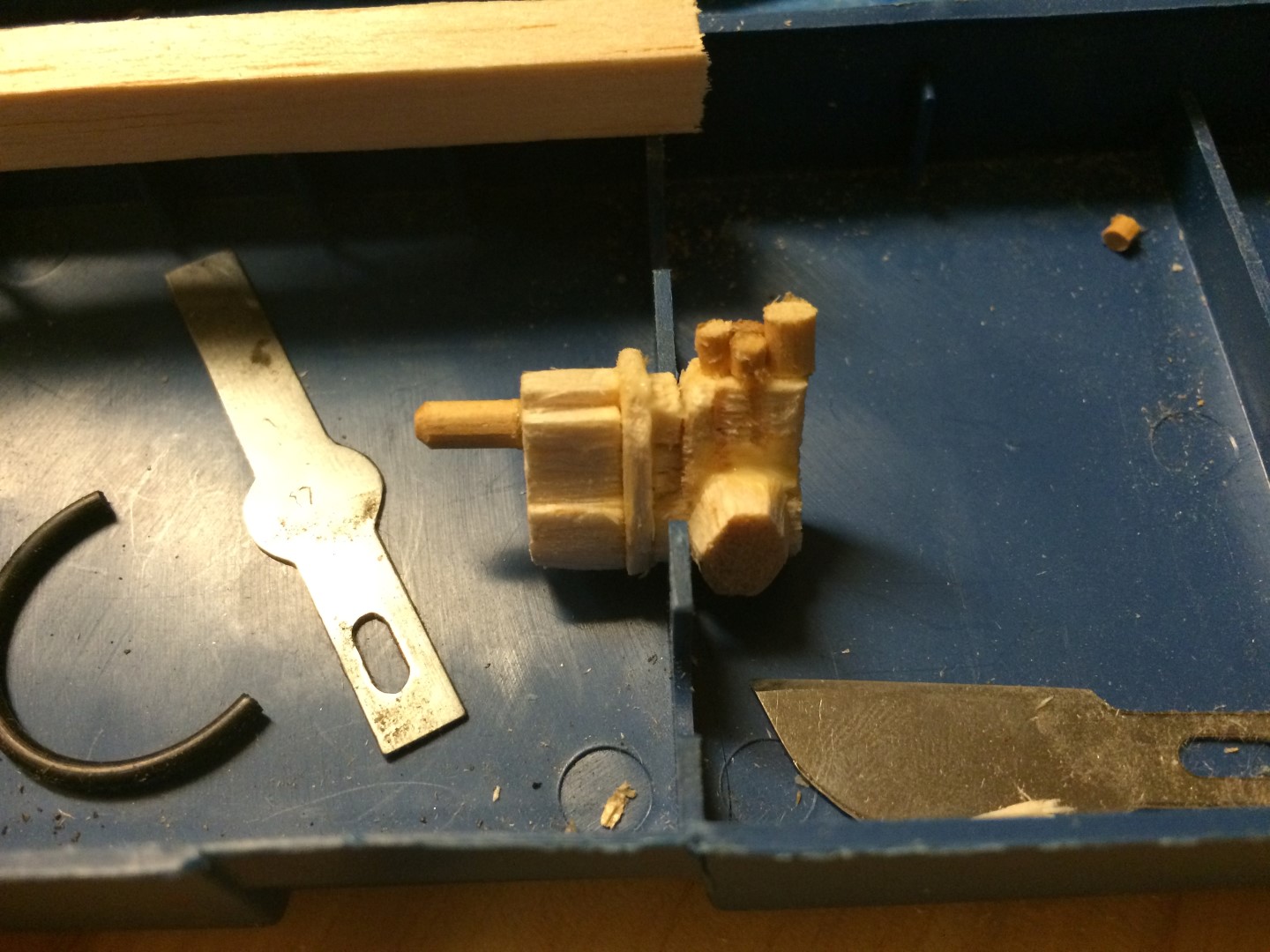
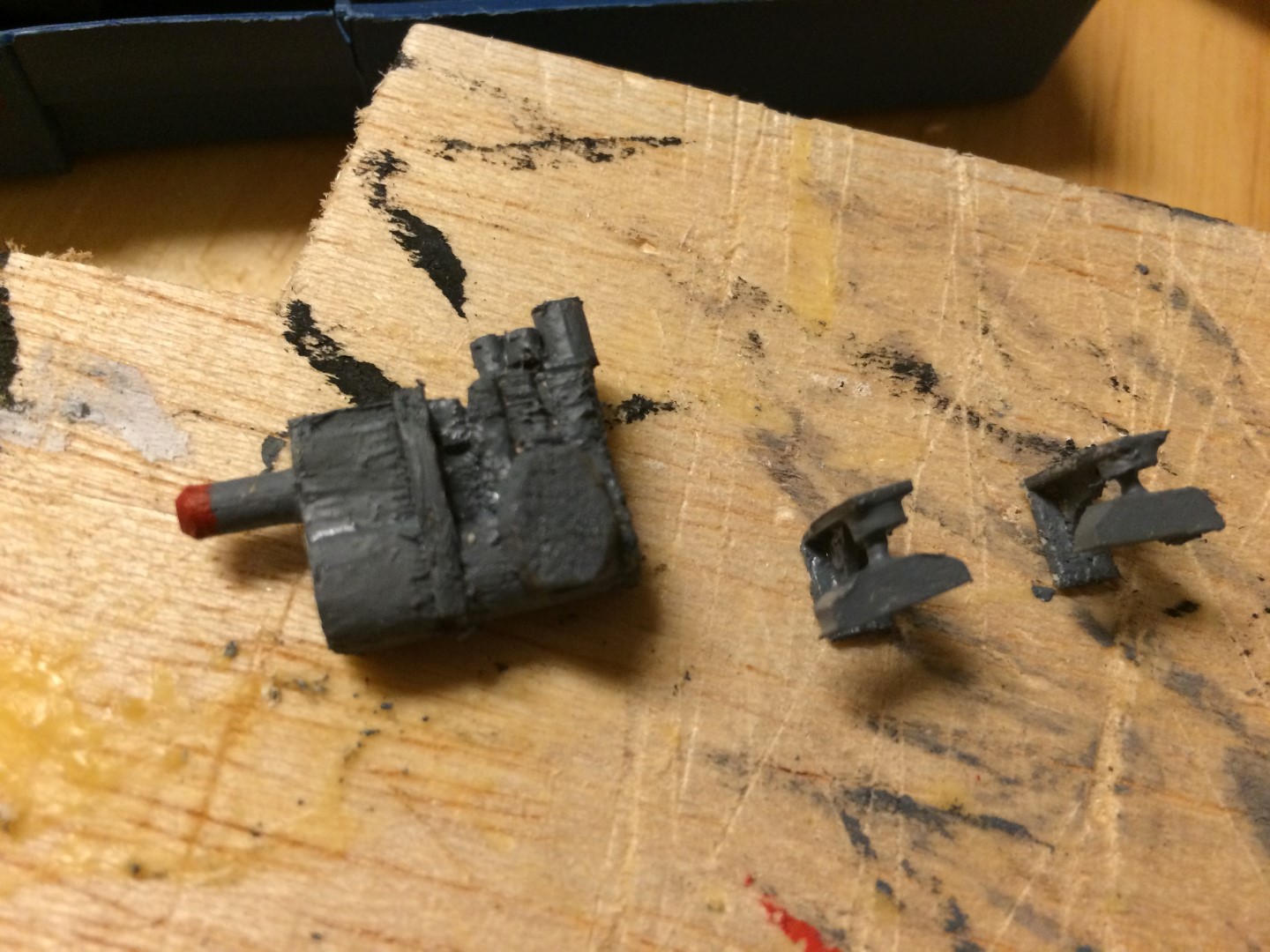
I made the E-stop cylinder first. I had to keep the parts in a contained location since they were sure to get washed away if I didn't.
Emergency Stop Pushbutton Cylinder
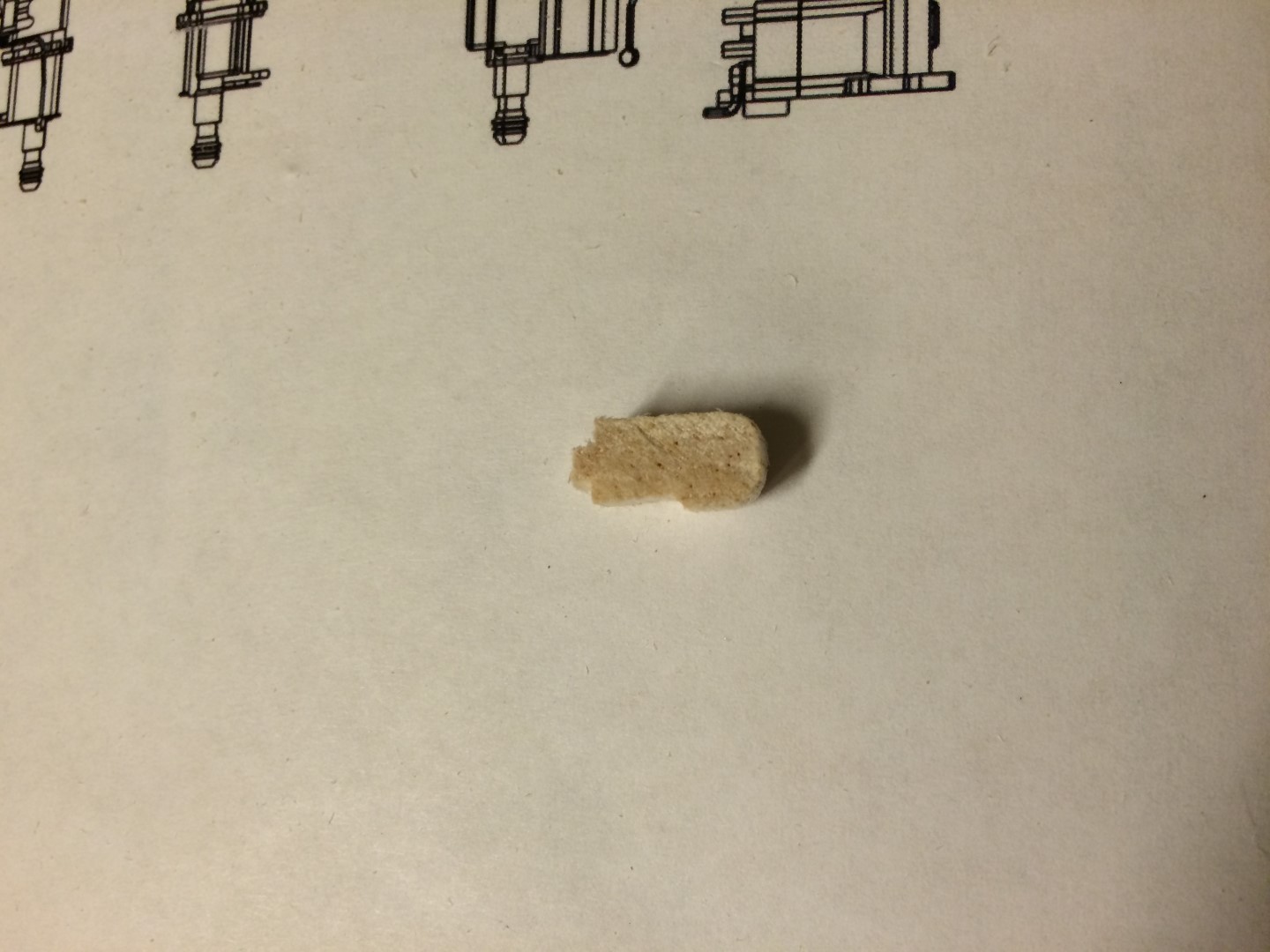
Next I made the first blocky part. I took a stick of balsa for which the height and thickness was appropriate, and cut it to length. Then I used a square file to 'cut in' the different reliefs into the side, and then a flat file to round out the bottom.
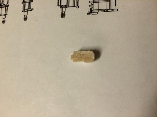
First Blocky Part
I used the same approach for the rest of the pieces - find an appropriately sized chunk of balsa and cut to size, then file as needed. I used a thin flat file to cut the vertical grooves in the second blocky part.
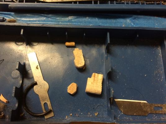
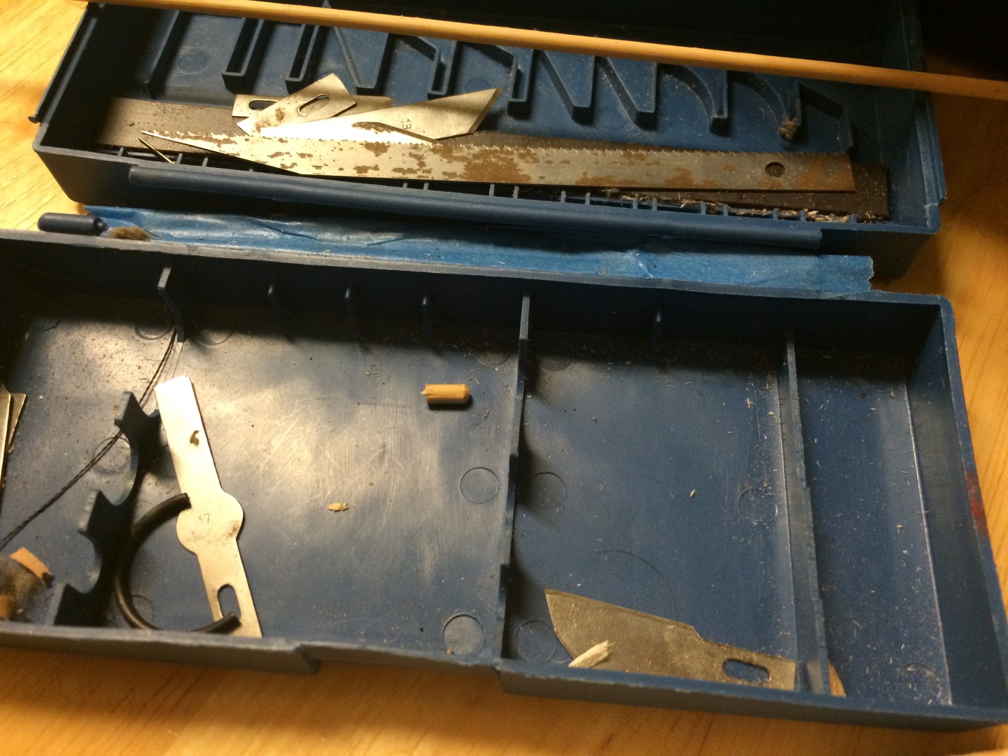
Most of the parts cut and shaped and safely put aside.
I used a toothpick for the injector connections, since my smallest dowel rod was 1/8" - too big for this size. Even the toothpick is a little large. But I again fell back on my conviction that essence is better than exactness, for this model. (There are certainly models where exactness is what defines them).
So, here are all the parts assembled.

Injector Assembly, Unpainted.
PAINTING AND AFFIXING INJECTOR PUMP AND ENGINE MOUNTS
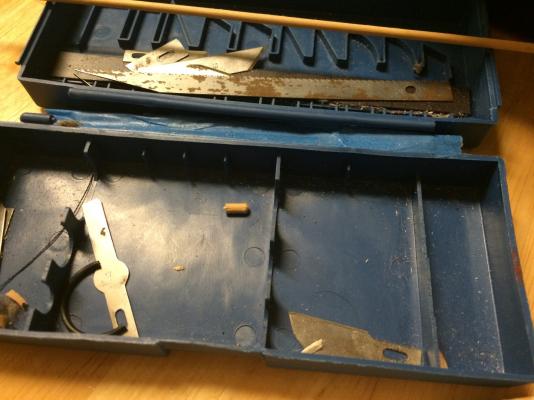
Remember those polystyrene engine mounts I made right off the bat but couldn't glue on? Yeah, neither did I until I found them rummaging through the top 'odds and ends' part of my tool box. It's a good thing I didn't put them on first - they would have been in the way at best and broken at worst.
Anyway, I painted them, and the injector pump...
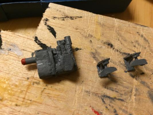
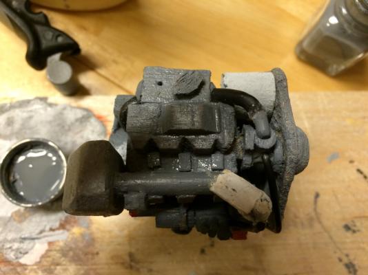
Injector Pump and Engine Mounts Painted
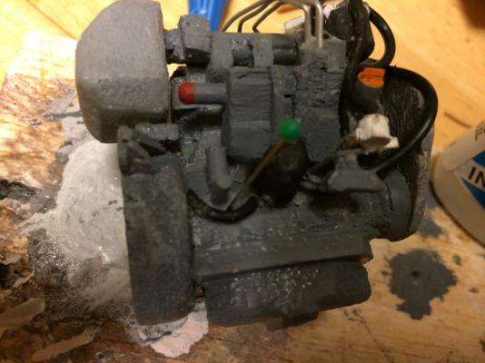
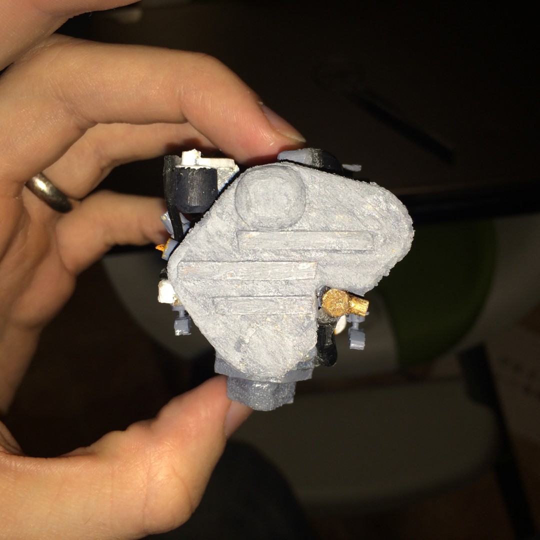
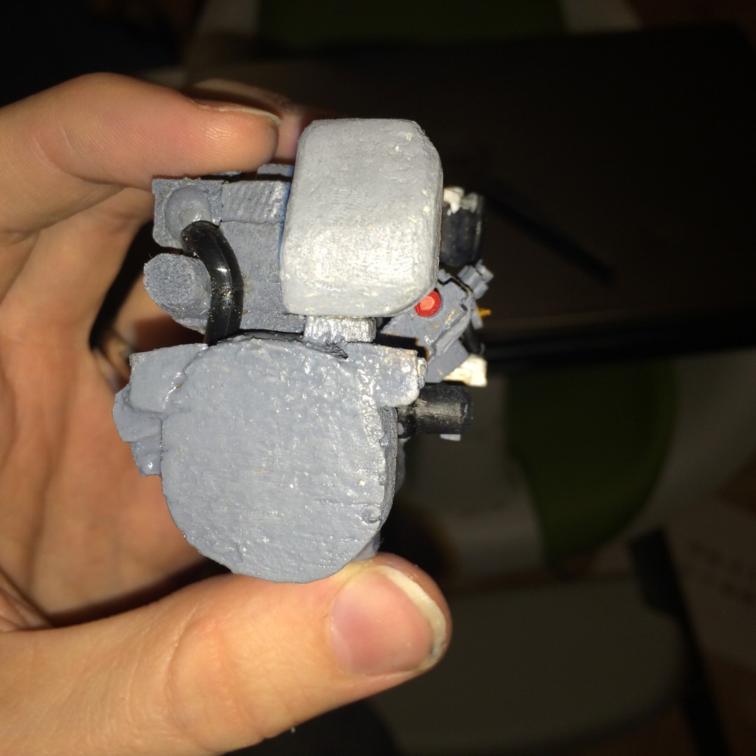
...and stuck them onto the engine. Below is a series of shots showing the current state.
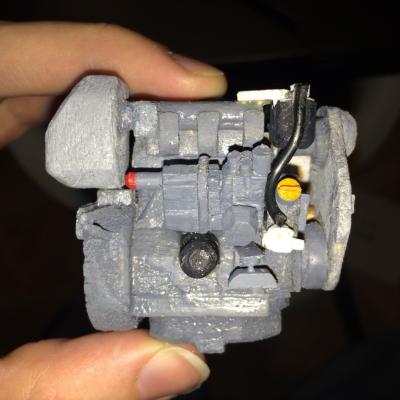
Engine Current State #1
Engine Current State #2

Engine Current State #3

Engine Current State #4
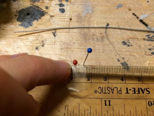
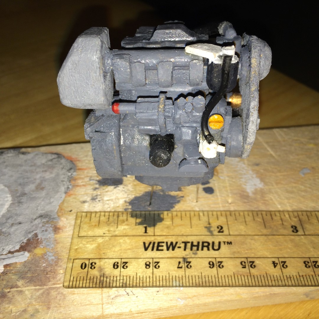
And, because flipping through large pictures, I sometimes lose scale, I added one of the engine next to the ruler.

Engine and Ruler, for Scale
Next up is, I think the exhaust outlet, and then it's just finishing up hoses. Oh, and the whole gear assembly for the saildrive unit.
-
Thanks Patrick!
I got some more time this evening to work on the model, so I can't keep the suspense about my hoses up too long. Oh well.
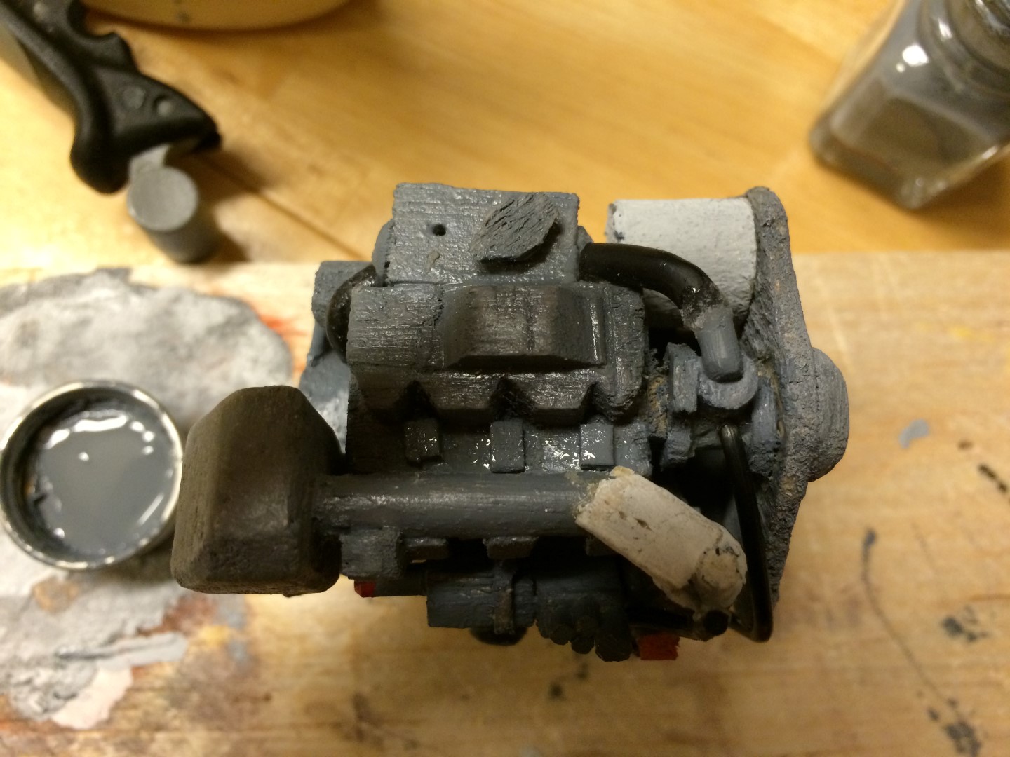
HEAT EXCHANGER END CAPS
So, the first thing I did was to make the dome-shaped end caps for the heat exchanger. There's an old adage that says 'work smarter, not harder.' Well, I think I lived up to that this time. I filed the dome shape into the caps BEFORE cutting them off the dowel. That way I had a grip while trying to do my filing. Then, I just cut it off at the tangent line, and voila, dome cap.

Dome Shape Filed into End of Dowel
Dome Cap Cut Off
Next I glued them onto the engine. I figured given their size, painting them in situ on the engine would be best. It turned out to be super simple and I didn't get paint anywhere I didn't want it!
I didn't take any pics specifically of that step, but you can see the new rounded ends of the heat exchanger in the next pictures.
HOSES, PART 1
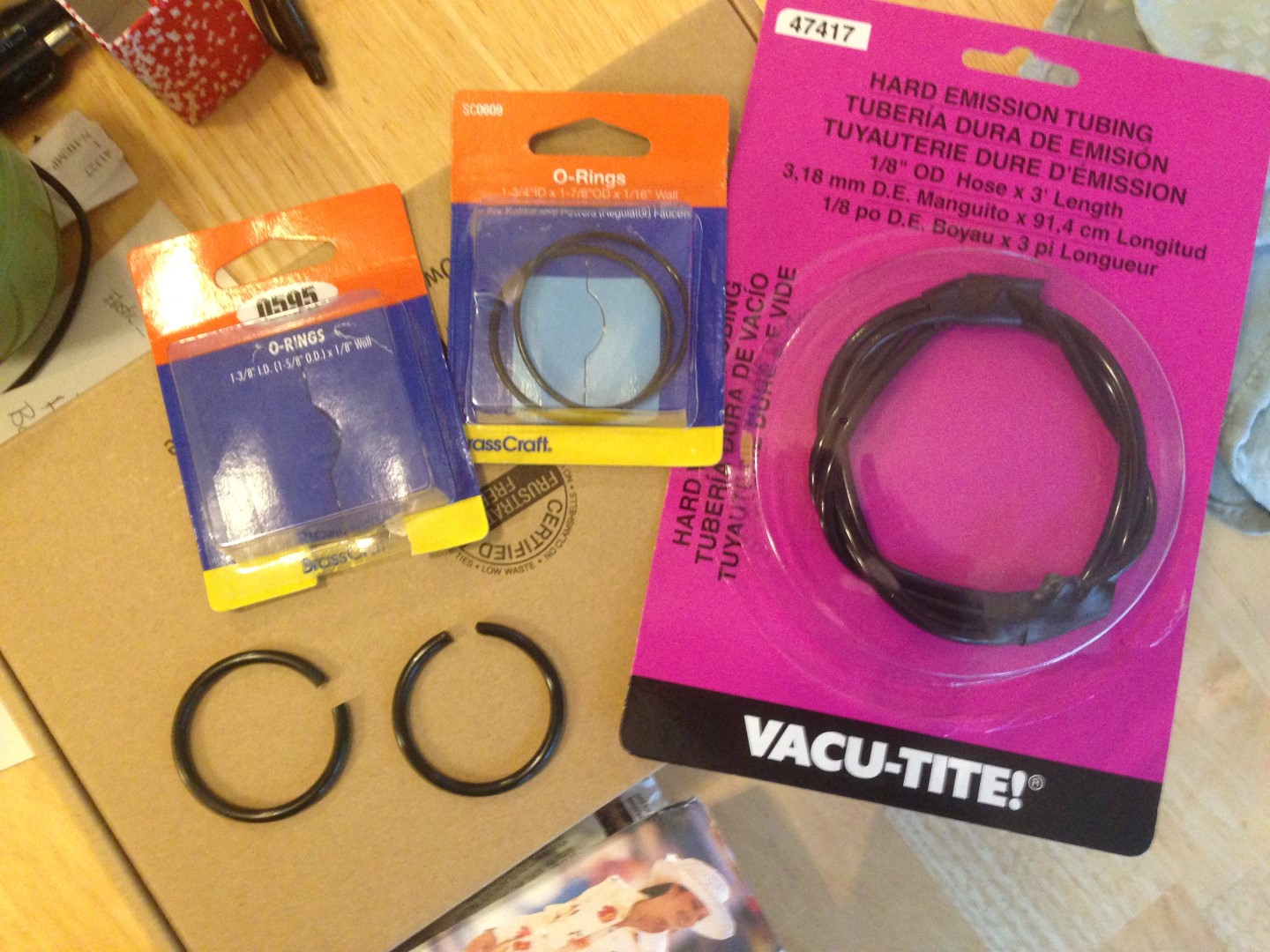
And now, my idea for the hoses I've been waiting months to implement: Rubber O-Rings from the hardware store.

O-Rings and Vacuum Tubing to Simulate Hoses
I also recently got some smaller diameter/smaller thickness o-rings for the smaller hoses. The ones in the picture above scale to about 3" hose in the real world - about right for main seawater hose and coolant hose for an engine this size.
And - it worked! so I don't have to show you a plan B and pretend it was my good idea

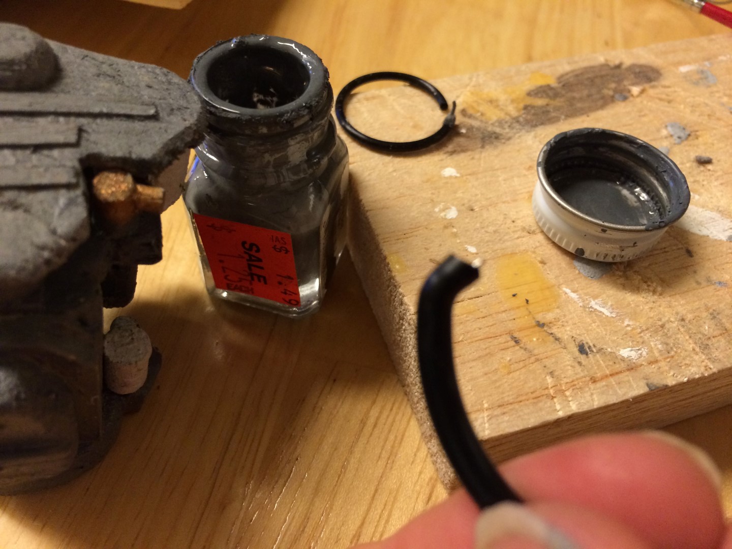
So, I started with the biggest, longest stretch - the main seawater supply to the heat exchanger. At first, I had this thought that I could use pins in the ends to secure the ends to the engine, but when I attempted, I had to press harder than I was comfortable, so I abandoned that idea. But, it led to another - I could use the pin to give the O-Ring enough rigidity to make sharp bends like there are at the connections.
Pin Driven into End

End Shaped at Angle For Seawater Pump Outlet Connection
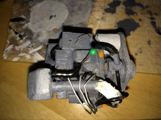
So I just started at one end, using thick super glue, and started gluing and pinning. Most of the time, I used the pins as guides rather than driving them through the O-Ring itself. There were a couple places where I had to do this because I was making it angry with bends it was never designed for (since it was supposed to be, you know, a ring.)

Side View of Seawater Hose
End View of Seawater Hose, Showing Connection to Heat Exchanger End Cap
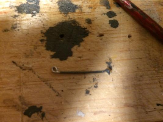
Next, I did a small diameter section of hose from the very little fuel system part (which is an electric on-engine fuel pump, I have learned) to the fuel filter. The challenge was that the connection at the fuel filter is a straight piece of small diameter tubing that the hose connects into at a Tee. So, I used a small piece of wire and ran it into the O-Ring perpendicular to the length. This ended up achieving the desired effect.
Wire into O-Ring

Small Diameter Hose In Place
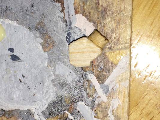
Finally, I did the short section of hose from the Coolant Pump to the Heat Exchanger. This was actually the hardest, since it was a short length and there wasn't anything to pin it to along the run. So I finally just applied super glue to the ends and set the engine at an angle that would make gravity and capillary action set the hose in place for me.
Coolant Hose (Top)
So far the glue seems to be holding. I am really stoked this worked so well.
Next on the list are the fuel system components (injection pump and injector lines) that are really complicated and that I keep putting off. Fortunately, I can't run more hoses until I get this done, since most of the remaining hoses connect to it or go around it in a way that I can't replicate without it there. So I guess I have to do it now.
(Given my amazing ability to avoid complex things I don't want to deal with, I'll probably actually end up doing the exhaust outlet or something next)
- captainbob, avsjerome2003, mtaylor and 3 others
-
6


40' Cruising Sailboat by BenF89 - 1:12 Scale
in - Build logs for subjects built 1901 - Present Day
Posted
Thanks Guys! It was a lot of studying followed by a lot of nail biting followed by a BIG sigh of relief and some hi fives at work.
As for the additional details I promised re: the boat........
GENERAL ARRANGEMENTS RE-DESIGN
Yup. I got a template for the lower deck, and used that to check the general arrangement I had developed in sketch form and then 3D model way back in the beginning, when I first set the scale to 1:12. Turns out that while I had MOSTLY got the hull form right by observing and guessing, I didn't quite get the shape right below the turn of the bilge (where it actually matters in a sailboat.) As a result, I had significantly less deck area to work with than I thought. The upside is that I was able to use the template I got to determine that a hull shell developed from my lines was close enough to right to use moving forward.
So I redeveloped the hull, scrapped the original arrangement, save for the cockpit size and companionway location, and started over. I printed off a sheet in 11x17 detailing the sheer plan, the lower deck plan, the companionway, and the cockpit. I pencil sketched a new arrangement over that. My second big 'breakthrough' in problem solving this arrangement was when I realized my 40 ft boat can't fit the arrangement of a 40' boat. The length isn't my limiting factor, the beam is. And no modern 40 ft cruising boat has less than 12 ft of beam. (Recall that, at scale, I have 10 1/2 ft of beam). So, I looked at boats with 10-11 ft of beam, which fell in the 30 - 35 ft range. I ended up using the arrangement of a Sabre 34 sailboat from the late 70's. (Of course, the Sabre 34 is really just a 'type' of sailboat for this size. There are really very few ways to fit a nav station, two double berths, a galley, a settee, and a head into a 34 ft boat. They end up being similar from an arrangements perspective.)
I penciled in my arrangement (see pic below), and then set out to model it.
Re-Design Initial Sketch
As I developed it in 3D, I made some additional changes that presented themselves as things came together. Of course, I do have a 40 ft boat, and a 34 ft boat arrangement fits in just 34 ft of the boat, leaving 6 ft of 'dead space' beyond what the 34 has. Well, I put some to use in a slightly larger than standard galley, some to use in a slightly larger than standard cockpit, and a chunk to use as an actual engine compartment. This was my favorite feature that I used the additional length for, as I know the challenges associated with engine access - both from pictures, anecdotes in books, and my own limited experience. So I was happy to be able to fit in a compartment with sitting-head space, accessed through a cockpit seat, that allows complete access to the engine and gear (as well as providing a space for aux equipment like a water heater and refrigeration/AC compressor/condenser, etc.
The other upside is that the arrangement is now much simpler, and therefore (in theory) easier to template and construct. And provides a good amount of open space to get in and actually play with it.
The series of screenshots below are representative of how I plan to actually present the boat - i.e. what is seen in the pic is what the boat will look like when complete, minus some details The point was to conceptualize how I would reveal the insides but retain the cockpit, and not have it look weird(er). Where pink shows up inside the cabin, there will either be a white polystyrene sheathing, or it will be finish planked. Where you can't see it from 'inside' the boat, it will remain unfinished.
Re-Design Plan View
Re-Design Stbd Fwd Isometric
Re-Design Port Fwd Isometric
Re-Design Inboard Profile CL Looking Port (Head BHDS hidden)
Re-Design Inboard Profile CL Looking Stbd
Re-Design Stbd Fwd Isometric with 'Pa's' for Reference
Below are a couple shots of the engine compartment. I haven't decided how/whether to create 'access' to this in the actual model. due to the delicate nature of the engine. So as it currently stands, the engine and drive will be there, but will be 'invisible.' One of those 'I know it's there' things.
Part of how I was able to make the arrangement work better also involved re-developing the cabin roof. I was able to get more use-able interior by widening the cabin top, primarily around midship. You can see the difference from the original concept in the comparisons below.
Original Concept for 1:12 Scale Arrangement
Revised Concept for 1:12 Scale Arrangement
So - to summarize where I'm at now. I have got a good, physical template for the lower deck. I used that to check the original arrangement, which didn't work. I re-arranged the interior based on the work I did developing the hull from the crazy offsets measurement work I did months and months ago. And now, I have a deck template and a working arrangement. (And an engine. Well, I need to do the gear.) I purchased a 12" x 48" piece of 1/8" modeling plywood to cut the deck out of, which will give me plenty of extra for some of the joiner work. I'm pretty well set to move forward into final production planning and then construction of the interior (FINALLY!) My biggest challenge now is tooling, namely my lack thereof. I haven't quite got an idea of how I'm going to cut these pieces out of 1/8" plywood. I have a few Exacto knives, and a drill, and some files. I can probably make something work with that, but I am open to clever suggestions.