-
Posts
3,152 -
Joined
-
Last visited
Content Type
Profiles
Forums
Gallery
Events
Posts posted by trippwj
-
-
Darn it. Do you have a strong keel clamp (the longer the better). How about spraying the bent area with windex until it's good and damp and then clamping it for a day or two?
Augie -
I have one of the Amati keel clamps that should be good to clamp the beastie near both ends. Would it make sense to put something wicked stiff along the keel when I clamp it to help press it back to plumb?
-
-
The clue about the Commandant USMC with the MoH gave this one away.
USS Neville (APA-9 and AP-16)
-
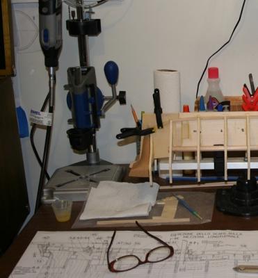
Continuing to move slowly with the Essex. I have installed the garboard strake supports on the port side, and getting ready to work on the starboard side.
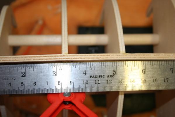
As I was taking these, I noticed what appears to be a bend in the bulkhead former about midships
I had been checking for squareness on the bulkheads and for straightness of the former while installing the bulkheads, so this caught me off guard!
I went back and took some additional high-resolution flash photos and found that there is a bend evident in the keel between bulkheads 10 and 7 with a max gap of 1.5mm from plumb at bulkhead 9 (length between bulkheads 7 & 10 is 16.7 cm, largest gap is at 6 cm). Will this create heartache and loss of sleep (not to mention hair) if I ignore it? Is this something that, short of tearing everything out and starting over, I can work around in some manner?
-
She is looking really nice - that cathead came out great!
-
Wayne your a sly old seadog, never said a word did you, and boy do you know how to make life hard for yourself.


I agree with Augie mate, but be careful with that 5x5 plank, it looks as though it's going to take the Garboard Strake, the positioning is going to be critical later on.
Good luck with both the translation and the build mate, and if you have no objection I would like to follow your journey.


Be Good
mobbsie
Key word there is "old"!!!
Welcome aboard, mobbsie - glad to have you along for the ride. I think Sjors has the popcorn machine set up in the corner.
-
Hey Wayne,Almost forgot how nice those older kits were without the pre-cut parts. Half the fun of making the kit was cutting out the parts and finishing them to fit.That's when kit builders needed a scroll saw. Mine just sits on a bench now out in the garage just waiting to sink its teeth into some 5mm ply

Frank
Greetings, Frank - will keep you posted on how that goes! If you want I can send you some to work on
 ;)
;) 
-
I will follow with interest as I also have this kit sitting in the closet.

/Mark
Greetings, Mark, and welcome. Thus far it has been enjoyable. It is quite a change as there are no instructions but rather seemingly haphazard drawings on the plans sheets. Most of the notations are just the dimensions, not guidance on installation. I did find a site with the sheets in English and Italian - they are not a perfect match (newer version of the kit than mine) but close enough that I can figure out what is being said!
My biggest concern is when it comes to cutting all those small pieces out of the wood sheets - something like 8 sheets with 10 to 100 small pieces on each one.
-
Hi Wayne
The Essex is a great looking kit with lots and lots of little details so that you can whittle away your free hours of shear enjoyment. I will pull up a chair and watch and will surely enjoy the show. I am still caught up in all of those hammock the DeAgostini web build log said that I needed 104 hammocks to lay horizontally, but I choice to install them bent in the center and hung vertically, sure did change the amount that I needed, I have ended up with 222 of those little hammocks all are installed but 10. I have been so caught up in these hammocks. And misted the launch of the Essex, and had to blow the snow twice this week, # 14 now, this sure has been a bitter winter so far. Enjoy.
Regards Lawrence
Thanks for the kind words, Lawrence. Glad to hear that there is some progress on getting some plans for the Annie M. Parker!
Your hammocks look fantastic on the Victory - I can only guess how long that took to get them looking so nice! As I recall fom other discussions, vertically is the way they were stowed.
Only had the one storm here this week - about 8 inches. Nice to have the ground covered again. If it is going to be cold, it may as well be snow covered!
-
Those pressed wood forms of the stern and bow drove me nuts getting them squared to match the center planking. They also caused a fair amount of twist to the bulkhead. If I had to do it again, I would do the balsa build up and fair method and plank like a traditional POB.
The pressed wood galleries are really nice and have potential. Maybe cut out the windows and re-frame and glaze?
I see you have a fair amount of time to spend on the jigsaw since these kits do not have pre-cut parts. One thing I liked about the printed plywood parts were that they made nice templates to make scratch parts out of hardwood. Hmm, I think I a feeling a bit of motivation to start back on my Endeavor. Thanks!
Scott
Scott -
Thanks for stopping by! I must admit to a degree of trepidation when it comes to cutting out all of those tiny bits - I guess the scroll saw will need to be brought out of storage. I have a nice space I can set it up in the basement - during war weather only (it is unheated and a tad chilly right now). Fortunately I have a great deal to do before I reach that stage!
The pressed wood bow & stern fillers went in well with no twist added, although I do have some sanding to do to get them flush with the bulkhead outer surfaces.
-
My dad didn't share a lot about his time in the Navy - mainly some letters he wrote to his parents when he was deployed. He went in during 1942, served until 1946 on Tin Cans - did a lot of R&D work improving sonar, a couple of convoy escorts across the pond. His interest in photography sprang from those days - they would take photos of the oscilloscope to show the expected display for specific conditions to use in training sonar operators. They had to develop them quickly and verify they came out else re-run the scenario.
-
S.os
It looks pretty nice.
I wish I hadn't lost my Blue Jacket's Manual. Seems to me there were diagrams of most everything in knots and splicing. Blasted shed leaked down through my whole seabag and a stack of text books I was keeping and turned it all to black mush. I used to be fairly good at splicing, although I did not use it much after A school. I'd been thinking of trying my hand at using splicing on my meridea running lines. I don't know if I can remember without my book for a refresher. I guess I can find some sort of references on the internet.
Was it 6 times the diameter of the line that the splice was supposed to go from it's start? or was it 6 times the diameter of the spliced part of the line?
Walt Biles
Geez, Walt - you prodded me to pull my Dad's 1940 Bluejackets manual off the shelf. For a short splice, both ends of rope are unlaid for about a foot. For an eye-splice, the line is brought back upon itself enough to give the desired eye size and then tucked into the body of the rope. For a long splice, and this one is a real kicker, the ends are unlaid farther than for a short splice. Big help there!
-
Sounds like it could be a new contest to try for the most distance. Next would be for accuracy and aerodynamics!
-
Coming along nicely, Tom. And my wife wondered why we kept all those tubs of Legos - Model building tools!!!!
- Mike Shea and CaptainSteve
-
 2
2
-
Wow, Sherry - those came out wonderfully! Have fun with those 120 little bitsy things...I am quite sure you will get them right!
-
Teddyedward - Welcome aboard!
The most effective way to get advice and suggestions is via a build log. See the post here http://modelshipworld.com/index.php?/topic/53-before-you-post-your-build-log-please-read-this-starting-and-naming-your-build-log/?p=210 for information on setting up your build log.
in terms of resources, there are many build logs for the Bluenose 2 here on MSW. You can glean a great deal of useful information from them. The order of rigging - opinions vary. Many experienced builders suggest doing as much of the pre-rigging as you can prior to installing on the model. Others strongly encourage doing it all on the model. Adding sails introduces a level of complexity i haven't dealt with yet, but I suspect they would be among the last pieces added since many of the blocks etc. need to be installed before they are hidden by a sail.
One book that may prove useful for you is The American Fishing Schooners, 1825-1935 by Howard Chapelle. In addition, there is a very good practicum for building a POF scratch built Bluenose available here http://modelshipbuilder.com/e107_images/custom/msbimages/eisnor/bn-1-4/Bluenose%20Practicum%20Standard.pdf (the section on masts, spars and rigging may be of use to you).
One additional resource which you may find useful is here - http://www.modelboatyard.com/bluenose2_articles.html
Good luck - looking forward to following along!
-
Thanks, all, for the information on the 5x5 mm pieces. Have gotten the Port side installed and preliminary fairing done - the rest will wait until i get ready to fair the full hull. Now on to the starboard side!
An additional question -
This does have the pressed wood stern galleries. If I were to try and scratch them, would I build up the stern framing as in a POF model? Right now I have the filler blocks in place that I would need to remove.
-
In the US, the foot is based on the International Foot which = 0.3048 meter. The US foot is essentially the same - the conversion just takes it to 10 decimal places (1 US Foot = 0.3048006096 meters). For those of us geeky enough to want more info, the National GS has a PDF format document from the National Bureau of Standards in 1959 (NBS is now NIST) called Refinement of Values for the Yard and Pound that defines the "U.S. Survey foot" as 1200/3937 meter or 0.3048006096 meters. For more detail on the SI units, see http://www.nist.gov/pml/wmd/metric/metric-program.cfm
The SI meter is now defined as the length of the path traveled by the light in vacuum during a time interval of 1/299,792,458 of a second.
- jud and Doreltomin
-
 2
2
-
There is some recent research (I need to find the sources - believe it was in The Mariners Mirror) that red was not necessarily as universally used as once thought (relates to cost of the pigment and other factors). For the Fair American, being a privateer, you could go with the buff or green and be as historically accurate as any other choice.
-
There were various styles used over the years. For a description (and diagram of one type) see the attached PDF from 1835-ish
-
Eddie -
The book by Peterson is definitely worth taking a look at, although it is focused on rigging a somewhat larger frigate from the same era. You may find that things lay out a touch differently on the smaller Snake. Another source, though much more complex, is James Lees The Masting and Rigging of English Ships of War, 1625-1860 ISBN 978-0870219481
Between the narrative and drawings in Lees and the exceptional drawings in Peterson you should be able to both understand and make any adjustments needed.
ENJOY!
-
-
-



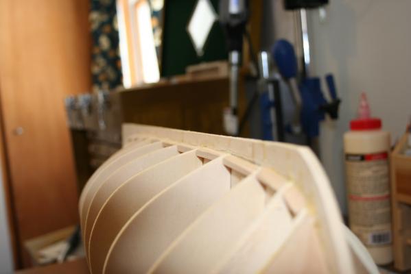
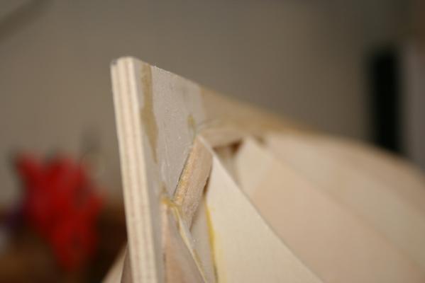
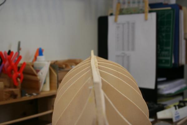
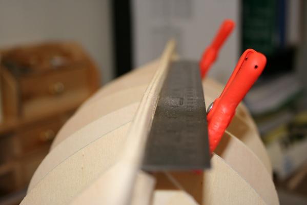
US Frigate Essex by trippwj - Aeropiccola - 1:70 Scale - POB
in - Kit build logs for subjects built from 1751 - 1800
Posted
Frank -
If clamping it doesn't work, then will probably resort to filler on one side and sanding it down on t'other to get it back to plumb! Planning to double plank it and copper the bottom, so would hide the deformity and repairs (I hope!)