HOLIDAY DONATION DRIVE - SUPPORT MSW - DO YOUR PART TO KEEP THIS GREAT FORUM GOING!
×


dafi
-
Posts
2,419 -
Joined
-
Last visited
Content Type
Profiles
Forums
Gallery
Events
Everything posted by dafi
-
 Still had some more rounds in the NMM, checked all available carronades, found them all different, but found some similarities. - The bolt of the lower part as near to the wall as possible, gives 2mm - Shortened the front of the sled gives 1,5 mm - makes 3,5 mm :-) - no feed for higher flor plate Ok let´s go for the infamous Texas carronades massacre ... ... new hole in the floor plate, new bolt on the lower part and shortened sled ... ... pushed back ... ... and now fits in the front ... ... also the radius fits much better :-) Have to admid the timberheads being quite close to each other. Now still is the mystery of the turning sled ... ... but I am sure we will find that out ;-) XXXDAn
 -
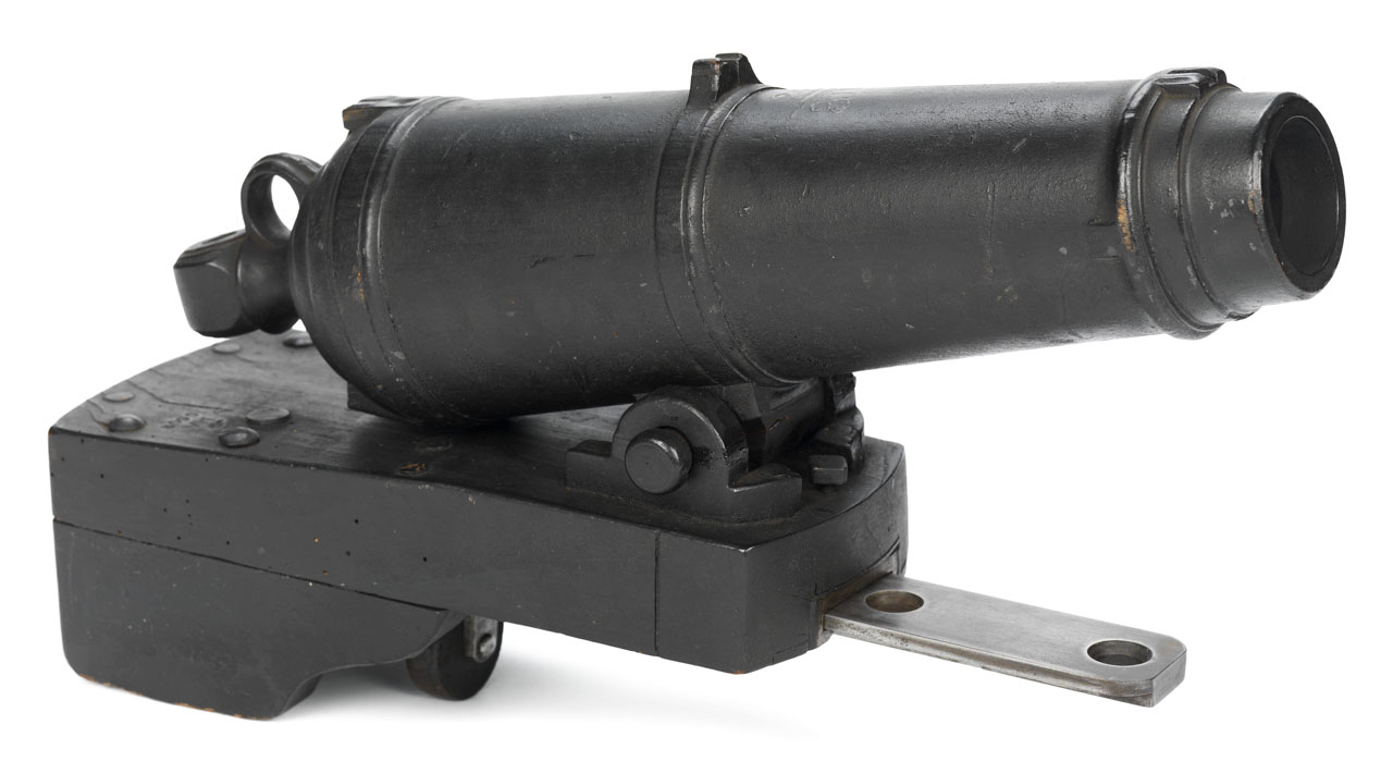
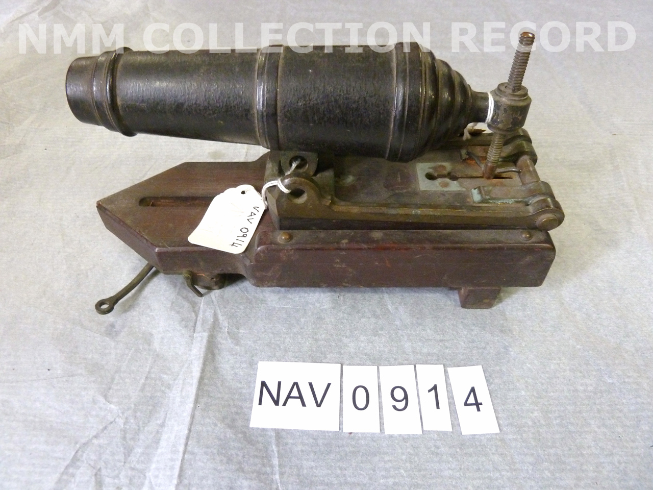
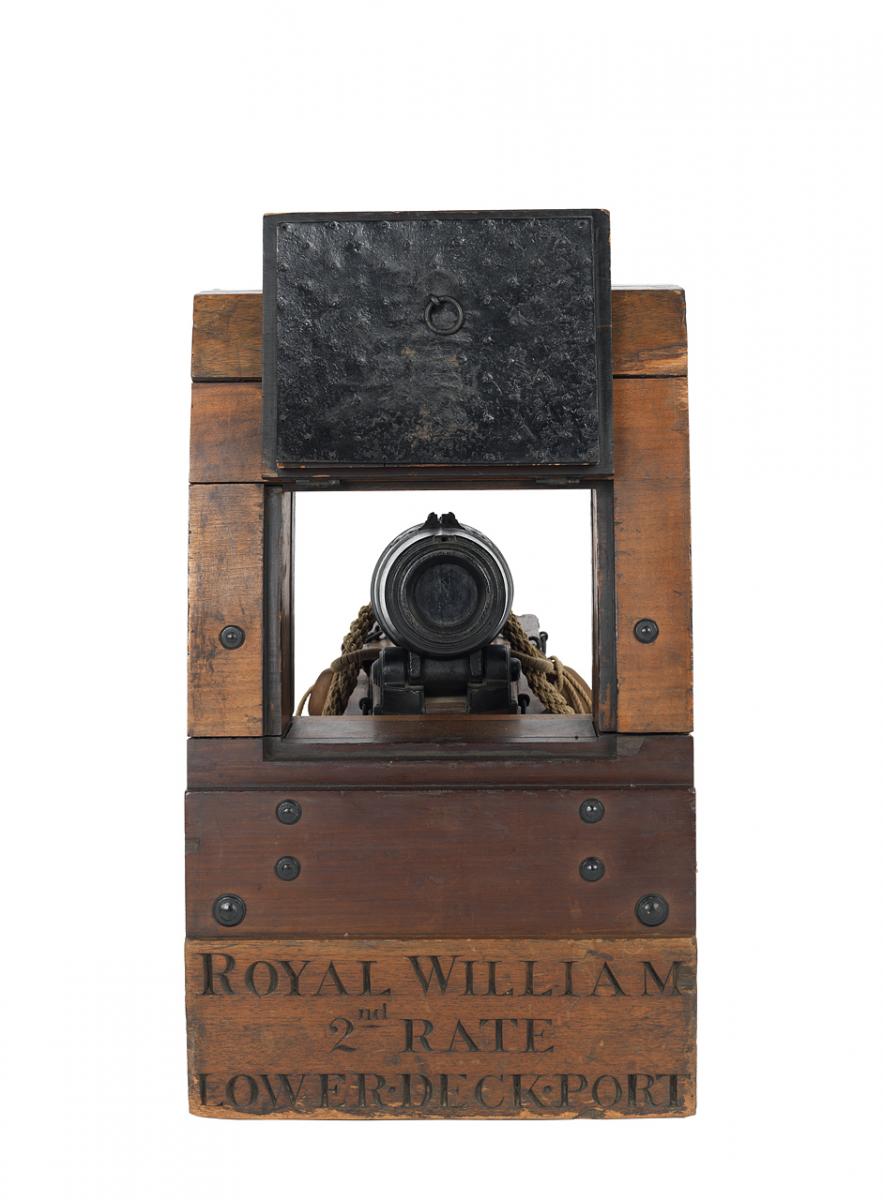
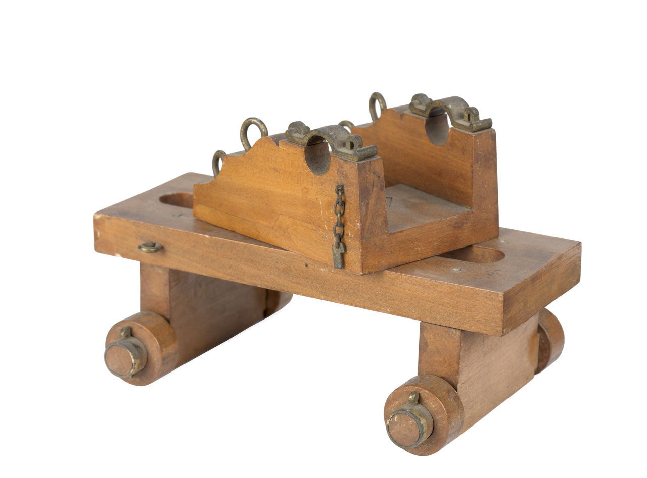
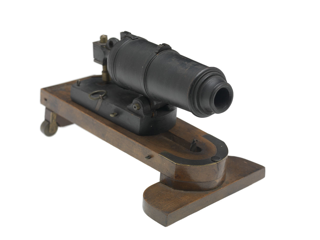
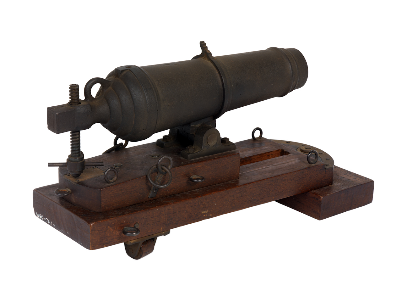
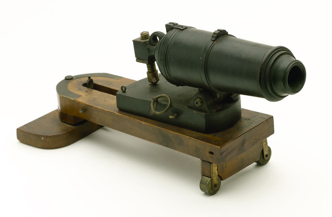
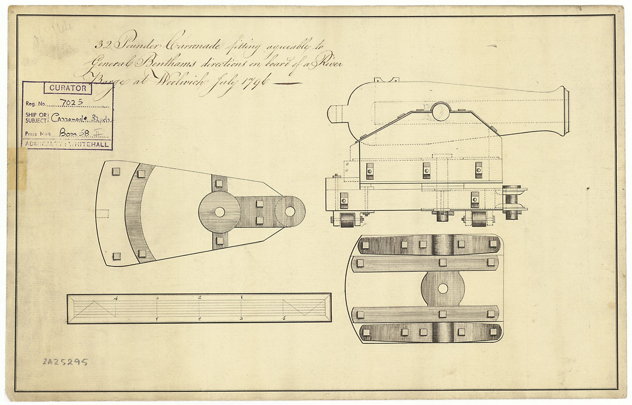
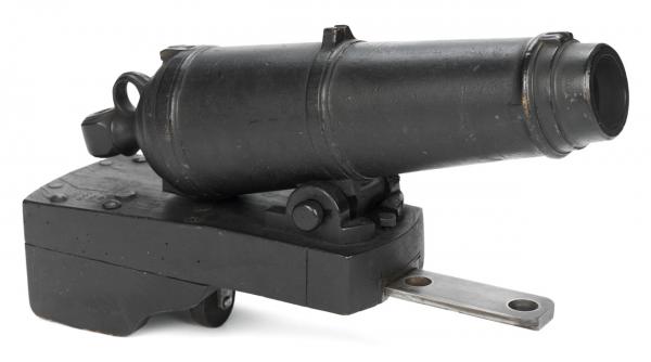
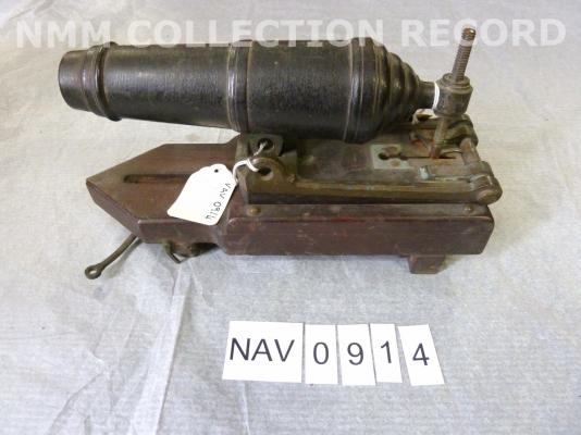
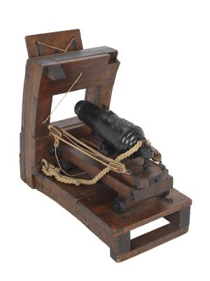
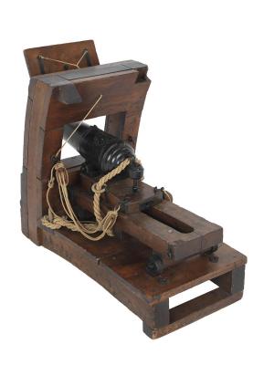
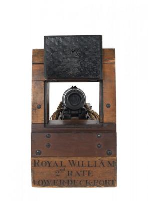
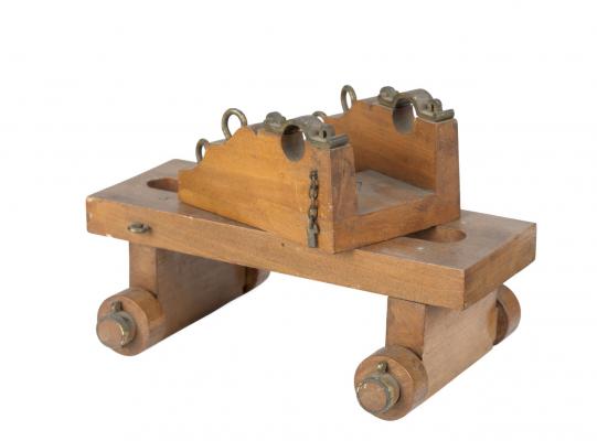
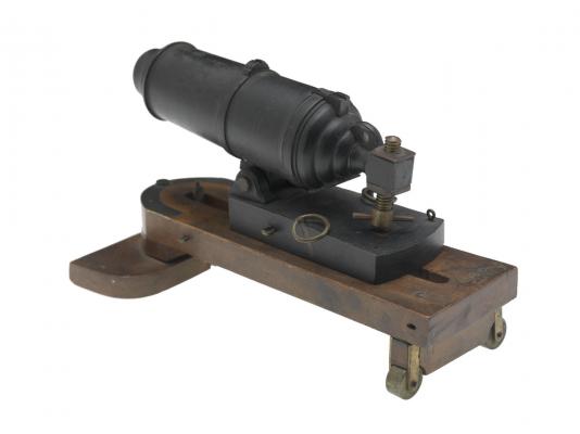
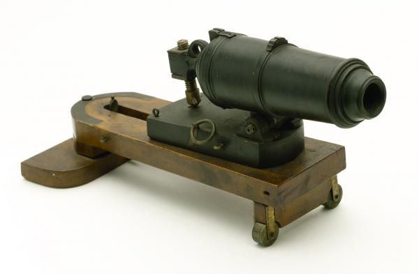
Thank you for all the hints. Some more NMM! Royal William Sectional design model depicting midship gun deck of the 'Royal William' (1719). Shows corronade. Model is decked, equipped and working. Model inscribed "Royal William 2nd rate lower. deck. port.". Date made circa 1800 http://collections.rmg.co.uk/collections/objects/68882.htmlSLR2927 Muzzle loading carronade Model of a carronade (about 1830) on a non-recoil carriage made entirely in wood with a metal swivelling retention bar. The gun is turned from a single piece of wood, painted black, and pivots on trunnions fixed to the bottom of the gun. The carriage is also made in wood and painted black. The bottom of the carriage has a metal rail running its entire length and extending from the front through which two securing holes are bored. Beneath the rail at the mid point of the carriage is a single transverse mounted wooden truck. http://collections.rmg.co.uk/collections/objects/68940.htmlSLR2985 Gun carriage for a 32 pounder Model of a wooden gun carriage for a 32 pounder. It has a raised flatbed on which the gun supports slide along for running in and out when firing and loading. The whole model is finished and varnished in natural wood and is complete with various fittings for mounting and working the gun, such as a pair of trunnion clamps, eyes for the rigging to work the gun and the brass edged track to work the slide mechanism. On the underside of the truck between the sets of wheels is inscribed "32 pounder by one inch scale.". http://collections.rmg.co.uk/collections/objects/68886.htmlSLR2931 Carronade model Wooden carronade model and mounting with brass fittings on swivelling slide. Mahogany slide. Date made circa 1840? http://collections.rmg.co.uk/collections/objects/43126.htmlNAV0914 Sea service carronade Instructional model of a sea service carronade on a sliding and pivoting wooden carriage. The gun has been cast and includes a sight, a prickhole and the mechanism for raising and lowering its elevation. It is mounted on a mahogany slide and the slide is mounted on a swivelling mahogany carriage. Both slide and carriage contain ring bolts for working the gun. The swivelling mechanism is pivoted on a rectangular piece of mahogany. At the back of the carriage, two sea service trucks allow the carriage to swivel in an arc. http://collections.rmg.co.uk/collections/objects/68878.htmlSLR2923 Carronade, 24pdr A model of a carronade on a pivoting sea-service sliding carriage (early 19th century) made in metal and wood, possibly walnut. The gun is patinated a dark bronze finish, has a number of reinforcing rings and has an integral front sight, aft sight, pommel and vent. The elevation thread, ring bolts, trucks and the curved edging strip around the front of the mobile pedestal are brass. The mobile pedestal and the housing for the horizontal rotation axis are made in a light-coloured wood. The sliding carriage is made in a dark wood, possibly stained or patinated. http://collections.rmg.co.uk/collections/objects/68873.htmlSLR2918 The last picture is quite interesting as it shows the sled pivoted by 180 degrees! XXXDAn


-
"... hot deal as the screw would just embed itself in the carrige. " That is why there is a metal plate underneath the screw. But that was my same question about the help of the wedge to ease the strain on the screw. See more here: http://modelshipworld.com/index.php/topic/10035-thinking-things-throu-carronade-carriages/ XXXDAn
-
Possibly need to rename the thread: Tinkering things throu ;-) Just for the model, I used a second guide ... ... and a breeching rope of 20 feet as this was indicated for 32 pounders. Fixed it gives a realistic looking overhang ... ... while in the front ... ... the radius is surprisingly limited. Cheers, Daniel
-
Thank you Sirs. Slow tinkering ahead ... ... creating more questions ... ... in the front the movement is limited by the eye bolts ... ... but in the back is the question how much overhang there was. Where was the limitation by the breeching rope? Sideways there were the wheels ... ... but interestingly all the contemporary drawing show a round bolt to hold the sled, possibly allowing a side turn, no second guide to be seen. Was this actually done. Ok, lets go for the trials ... ... made some timberheads ... ... the half circle was still moved as the timberheads were too far apart. Just for the model, I used a second guide ... ... and a breeching rope of 20 feet as this was indicated for 32 pounders. Fixed it gives a realistic looking overhang ... ... while in the front ... ... the radius is surprisingly limited. Cheers, Daniel
-
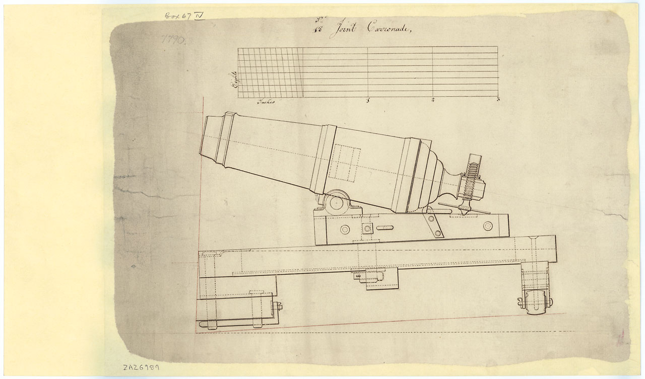
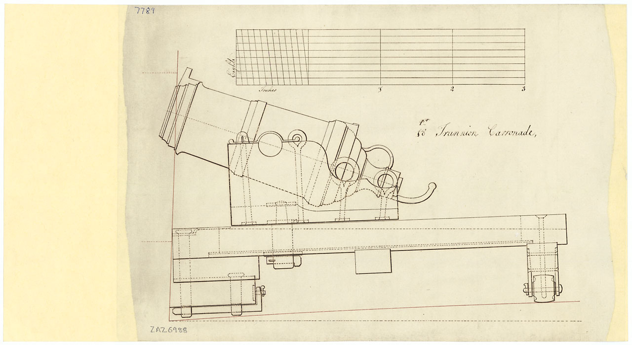
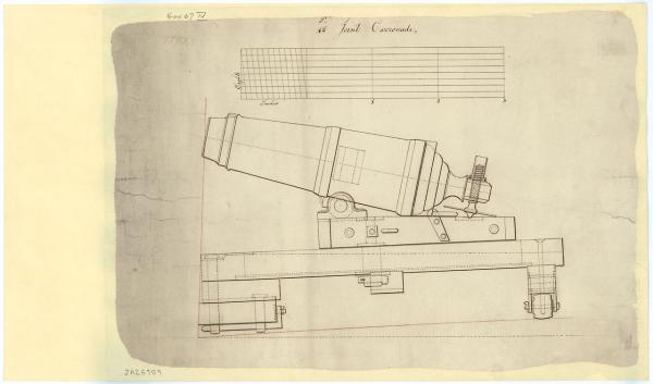
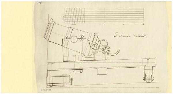
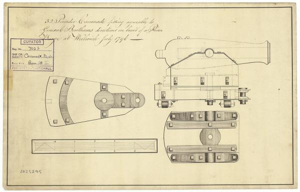
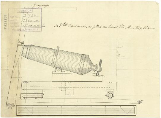
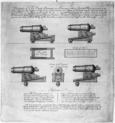
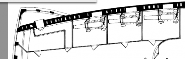
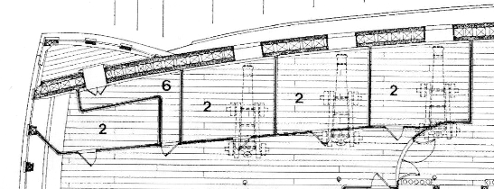
Here a bit of NMM NMM Description and illustrations of a 24-Pounder Carronade on a Carriage etc with key) (Misc 60A) Possibly a early model, with round bolt but second guide for the slide.. http://collections.rmg.co.uk/collections/objects/147421.html PAH7474 Helena (1804) Plan showing the elevation of a 32-pounder carronade as fitted to Helena (1804), a 16-gun Ship Sloop. A letter dated 12 August 1804 to Sir William Rule from Robert Seppings at Chatham Dockyard explains the reasons for the plan. Is this thing underneath a stop? http://collections.rmg.co.uk/collections/objects/83650.html zaz3859 32 pounder carronade (1796) Plan showing the elevation, carriage plan, and deck plate plan for a 32 pounder carronade, fitting agreeable to General Bentham's directions, on board a river barge at Woolwich. Date made Circa July 1796 http://collections.rmg.co.uk/collections/objects/85086.html ZAZ5295 18 pounder Joint Carronade Plan showing the port profile for a 18 pounder Joint Carronade on its Slide Mounting. Joint Carronades had a metal loop on the bottom instead of trunnions to fix it to the slide mounting. Note: The date is taken from B. Lavery, "Arming and Fitting of English Ships of War", page 131. http://collections.rmg.co.uk/collections/objects/86780.htmlZAZ6989 18 pounder Trunnion Carronade Plan showing the port profile for a 18 pounder Trunnion Carronade on its Slide Mounting. A trunnion Carronade was fixed by the trunnions either side of the gun to the slide mounting. Note: The date is taken from B. Lavery, "Arming and Fitting of English Ships of War", page 131. http://collections.rmg.co.uk/collections/objects/86779.htmlZAZ6988 ... and one more :-) ZAZ6989 Interresting: - All carriages have a round bolt with a coin to adjust the friction and no second guide at the slot - Is the thing underneath the carriage a stop? But I know at least one carriage where the bolt is behind the "stop" - If this is the stop, a pivoting around the bolt would be beneficial to load the guns, especially seen by the weight of heavy shop. Funny: The mount for the back ring of the breeching rope shows on the Vic in P. and in McKay on the top backwards, on all the drawings it is pointing foreward, which makes more sense. Stupid me, I followed McKay and the Vic. in P. (no bashing as I like his work!!!) Cheers, Daniel
-
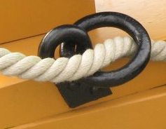
There was a thread in MSW.1 but it vanished ... It all starts that usually right handed people spun the yarn. These are laid/twisted several times, each time changing direction. Thus the "normal" ropes result in a Z-twist for conformity and easy splicing. If stronger ropes are needed, three or 4 ropes (sometimes with a core) are laid/twisted again with change of direction, this resulting in the S-twist. Those to be found on anchor cables and main and fore shrouds (mizzen to be checked). Steel somewhere mentions from which diameter the rope should be changed to cable, my memory says 9 inch. If thinner, cables were called cablets. It took me some time to find in Nares, that the guns used in the 1860ies used left handed S-twist ropes. In the making, at one stage, the change of direction is not done, thus resulting the rope to be more flexible to go round small diameters and being more elastic in strain - both perfect for the breech and the ring - , but on the other hand soaking more water, that is why not used in rigging (extra weight if wet). Older pictures of the Vic show right-handed Z-twist ropes as breech lines, those were changes against left handed S-shapes in the 2000ies. - Also a preventer breeching line was introduced in those days for 36 an 24 pounders - still would be very thankful for hints about those ones, Goodwin sounds quite confident about them as much as he is about the lay. Also for the same reason, about that time, the messenger was exchanged from a cable to a left hand rope, possibly because of the tight diameter of the capstan (a cable is much more sturdy) ... ... and also the lay still has now the same direction as the anchor cable, thus facilitating the nipping. Small notice: modern cable cars have their steel cables also done as a special left handed ropes to ease the wear by going around the wheels in the valley and on the top side. Hope this helps, Daniel
- 29 replies
-
- 1
-

-
- Rope making
- z twist
- (and 2 more)
-
Sorry Siggi, just saw your question by now. McKay shows them along the hull in an fore-aft position which works quite well. Cheers, DAniel
-
Thank you all for comments and likes! Izzy, I do not know about nori glue, but to file the material, I think most glues are not strong enough. The material I embedded the monogrum upside down is a normal plastic card/sheet, standard material. To make sure, I only sink in one monogram, which will be destroied by taking it out again. But it leaves a wonderful form for the other ones to be held in - just place the monogram upside down in the form, no glue required, just filing slowly and carefully :-) Cheers, DAniel
-
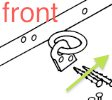
While building I found some of my usual questions about the carriages of carronades with sliding upper parts as seen on HMS Victory:-) Carriages: In the drawings that I know, the upper sliding part is linked by a round bolt to the lower part. This bolt moves backwards in a long slot of the lower part. In the front the forward position of the movement is limited by the eyebolts ... ... and drawings show a quite spectacular overhang in the backward position, that - seen the slot - could be even more than 50 %. How much did the breech line allow? As the wheels already allow a sideways movement ... ... it is intersting, that with the round bolt, the sled with the barrel would allow a turn too. Could this be? Coin: In drawings or models in NMM the guns are displayed without coin if a threaded rod for height adjustment is used. But seen the turning radius around the low situated trunnions would transfer all energy onto the threaded rod, and therefor on the point on the bottom of the rod where it meets the carriage. Would a coin relieve the rod in this situation? Questions over questions, Daniel
-
Ok trial number 4: Took a monogram and sank it by half into a poly ... ... broke it out ... ... and took the poly as holder to file down the backsides of the monograms down to half ... ... and bingo :-) Some other side theaters of war ... ... rolled the wire for the thread rod with the filr to give it some structure ... ... and carved the bearings of the trunnion out of Evergreen. On the last picture one can see that the sliding part has to slide over the mounts of the wheels, so it means, they have to be flush in the surface. So marked the position on the circle ... ... and used a dummy for testing. First drilled a basic hole ... ... ground a old scalpel into shape ... ... and formed the drilled hole. And the trials shows that it fits :-) So assembled the carriage and barrel, splashed some paint onto it, fitted the appropriate eyebolts and it looks ok ;-) Old and new side by side ... ... old - once state of the art - ... ... and a bit pimped ... ... and it seems quite ok :-) XXXDAn
-
Thank you Frank! On the last picture one can see something, that I was bothering about since some time. The monogram appears sitting quite thickly on the barrel. I already used the thinnest material available from my supplier, 0,2 mm equals 2 cm in original. The original monogram is about 5 to 10 mm mm but has much more washed outlines. Time to tinker a bit and to see what still is possible :-) Two versions were spooking around my wired minds for some time - lets go for the phantoms :-) Version 1 sinking the monograms with a soldering iron. Worked surprisingly well, it was quite easy to sink it evenly ... ... until I saw the bulges of diplaced material all around. Difficult to take out, ok forget it. Version 2 were thin castings, like those I do successfully for the coat of arms of the entry port. Took two monograms and hammered them into the poly ... ... casted twice ... ... but missing a good form success was not coming. Some carvings of the form did not help. Then came version 3, gluing the monograms and filing the edges off. Looked great without color but with color splashed over ... ... merda ... ...
-
Looking back in history, February 2010 "... and the carronades with wheels and elevation screw." For those days a vast improvement towards oob. But since then things went a bit nuts, so time to look for Carronade 2.0. The basic form fits so far quite well, fitted two more reinforcement rings on the original places, made from my tinnest Evergreen strips, but still sanded thinner and rounded with abrasive sponges. Also the iron sight was replaced and a base for the gun lock created. The bed of the carriage got the slot for the traveling part. The old coin and bearing were removed. For one of the guns a new sliding part was tinkered ... ... and I enjoyed the detail of putting in the base plate for the elevation screw flush with the surface. The rolls fitted for the carriage are 1,5 mm poly and comply to my understanding of a decent size of parts: fits into the "C" of a Cent ;-) Also the gunlocks do justice to this specification ... ... the flaps were bent ... ... and with the monograms we approach version 2.01. Cheers, Daniel
-
Hyho, small dafi was aloud to tinker some more bits ... ... first the freshly pressed ones ... ... by the way that is the way they looked in their former lifes :-) And as dafi likes to do messes ... ... but there is nothing better ... ... than a fresh caulked deck! XXXDAn
-
Fabulous Dirk, you win a beer next time we see :-) And we proudly announce ... ...hihihihihihihihi... ... my next modeling tool ... ...hihihihihihihihi... XXXDAn
-
Always a joy to see your progress. Cheers, DAniel
-
... good old times ... ... you can leave your head on ... ... and who discovers the parts from entry of 09.03.? Cheers, Daniel
-
Dafi was a taylor ... ... he shortened my coat and scarved my shirt ... ... he put my head right back in place, ... ... and stuck paper tails on my bum. ...hihihihihihihihihi... XXXDAn
-
*blow*... ... waving the dust away ... ... oh really, there is a building report appearing :-0 Lots of work means loads of pennies for the building :-) The only flaw is that there is little time for the builds, the only time for forums is when hanging in a boring telefone call or while the computer is rendering or saving. But it looks like times are coming back *joy* And as everybody sayz to start with something small ... Cheers, Daniel
-
H.M.S. Victory, Heller, 1/100, Onward and Upwards.
dafi replied to Izzy Madd's topic in Plastic model kits
Hy Izzy, Google pictures show the veneer pins looking as the ones that I deliver with my parts. Have a look, they sell these in the sewing shops in different thicknesses. The ones coming with shirts (here in Europe) are a tad thicker than the one I use. Also there ia a large variety of head sizes. But as seen in my report you can easily fix that :-) Cheers, Daniel -
H.M.S. Victory, Heller, 1/100, Onward and Upwards.
dafi replied to Izzy Madd's topic in Plastic model kits
A small selection "The 100-Gun Ship Victory (Anatomy of the Ship Series) " fom McKay http://www.amazon.com/100-Gun-Ship-Vict ... 229&sr=1-1 "HMS Victory: her construction, career and restauration" from McGowan with drawings from McKay http://www.amazon.com/HMS-Victory-Alan- ... 109&sr=8-1 "The Anatomy of Nelson's Ships" from Longridge http://www.amazon.com/Anatomy-Nelsons-S ... 365&sr=1-1 "Rigging Period Ship Models: A Step-by-Step Guide to the Intricacies of the Square-Rig" from Petersson http://www.amazon.com/Rigging-Period-Mo ... pd_sim_b_7 "Owners´Workshop Manual" from Goodwin http://www.amazon.co.uk/HMS-Victory-Man ... =8-1-fkmr1 Nice to have: "The Construction and Fitting of the English Man of War: 1650-1850" from Goodwin http://www.amazon.com/Construction-Fitt ... pd_sim_b_4 "Arming and Fitting of English Ships of War, 1600-1815" from Lavery http://www.amazon.com/Arming-Fitting-En ... pd_sim_b_5 Supplementary "HMS Victory" from Hackney (German Version): because of the planset included -
H.M.S. Victory, Heller, 1/100, Onward and Upwards.
dafi replied to Izzy Madd's topic in Plastic model kits
Hello Izzy, the good thing is, even without etch parts one can make a magnificent model out of this box :-) Have a look at my build and you will find most parts described how they can be build without using after market parts. But if you wish to use some, all parts are available separate, so one can pick the things that are useful. Another useful link is http://pete-coleman.com/forum/ This site is largely dedicated to the Heller-model with many hints and tricks. I hope this helps, cheers, Daniel