HOLIDAY DONATION DRIVE - SUPPORT MSW - DO YOUR PART TO KEEP THIS GREAT FORUM GOING!
×


dafi
-
Posts
2,419 -
Joined
-
Last visited
Content Type
Profiles
Forums
Gallery
Events
Everything posted by dafi
-
 Love it, great work!!! XXXDAn
 -
EXERCISE of the great guns. 1st. Silence. 2d. Cast loose your guns. 3d. Level your guns. 4th.Take out your tompions. 5th. Run out your guns. 6th. Prime. 7th. Point your guns. 8th. Fire. " The man who takes care of the powder is to place himself on the opposite side of the deck from that where we engage, except when fighting both sides at once, when he is to be amid-ships. He is not to suffer any other man to take a cartridge from him, but he who is appointed to serve the gun with that article, either in time of a real engagement, or at exercise. " Lanthorns are not to be brought to quarters in the night, until the midshipman gives his orders for so doing to the person he charges with that article. Every thing being in it's place, and not the least lumber in the way of the guns, the exercise begins with, 1st. Silence. At this word every one is to observe a silent attention to the officers. 2d. Cast loose your guns. " The muzzle lashing is to be taken off from the guns, and (being coiled up in a small compass) is to be made fast to the eye-bolt above the port. The lashing-tackles at the same time to be cast loose, and the middle of the breeching seized to the thimble of the pomillion. The spunge to be taken down, and, with the crow, handspec, &c. laid upon the deck by the gun. "N.B. When prepared for engaging an enemy, the seizing within the clinch of the breeching is to be cut, that the gun may come sufficiently within-board for loading, and that the force of the recoil may be more spent before it acts upon the breeching. 3d. Level your guns. " The breech of your metal is to be raised so as to admit the foot of the bed's being placed upon the axle-tree of the carriage, with the quoin upon the bed, both their ends being even one with the other. " N. B. When levelled for firing, the bed is to be lashed to the bolt which supports the inner end of it, that it may not be thrown out of it's place by the violence of the gun's motion, when hot with frequent discharges. See fig. 17, plate VII. 4th. Take out your tompions. "The tompion is to be taken out of the gun's mouth, and left hanging by it's laniard. 5th. Run out your guns. " With the tackles hooked to the upper-bolts of the carriage, the gun is to be bowsed out as close as possible, without the assistance of crows or handspecs; taking care at the same time to keep the breeching clear of the trucks, by hawling it through the rings; it is then to be bent so as to run clear when the gun is fired. When the gun is out, the tackle-falls are to be laid along-side the carriages in neat fakes, that when the gun, by recoiling, overhauls them, they may not be subject to get foul, as they would if in a common coil. 6th. Prime. "If the cartridge is to be pierced with the priming wire, and the vent filled with powder, the pan also is to be filled; and the flat space, having a score through it at the end of the pan, is to be covered, and this part of the priming is to be bruised with the round part of the horn. The apron is to be laid over, and the horn hung up out of danger from the flash of the priming. 7th. Point your guns. At this command the gun is, in the first place, to be elevated to the heighth of the object, by means of the side-sights; and then the person pointing is to direct his fire by the upper-sight, having a crow on one side and a handspec on the other, to heave the gun by his direction till he catches the object. " N. B. The men who heave the gun for pointing are to stand between the ship's side and their crows or handspecs, to escape the injury they might otherwise receive from their being struck against them, or splintered by a shot; and the man who attends the captain with a match is to bring it at the word, " Point your guns," and kneeling upon one knee opposite the train-truck of the carriage, and at such a distance as to be able to touch the priming, is to turn his head from the gun, and keep blowing gently upon the lighted match to keep it clear from ashes. And as the missing of an enemy in action, by neglect or want of coolness, is most inexcusable, it is particularly recommended to have the people thoroughly instructed in pointing well, and taught to know the ill consequences of not taking proper means to hit their mark; wherefore they should be made to elevate their guns to the utmost nicety, and then to point with the same exactness and having caught the object through the upper-sight, at the word, 8th. Fire. " The match is instantly to be put to the bruised part of the priming; and when the gun is discharged the vent is to be closed, in order to smother any spark of fire that may remain in the chamber of the gun; and the man who spunges is immediately to place himself by the muzzle of the gun in readiness, when, at the next word, 9th. Spunge your gun. "The spunge is to be rammed down to the bottom of the chamber, and then twisted round, to extinguish effectually any remains of fire; and when drawn out, to be struck against the out-side of the muzzle, to shake off any sparks or scraps of the cartridge that may have come out with it; and next it's end is to be shifted ready for loading; and while this is doing, the man appointed to provide a cartridge is to go to the box, and by the time the spunge is out of the gun, he is to have it ready; and at the word, 10th. Load with cartridge. The cartridge (with the bottom end first, seam-downwards, and a wad after it) is to be put into the gun, and thrust a little way within the mouth, when the rammer is to be entered; the cartridge is then to be forcibly rammed down, and the captain at the same time is to keep his priming-wire in the vent, and, feeling the cartridge, is to give the word home, when the rammer is to be drawn, and not before. While this is doing, the man appointed to provide a shot is to provide one (or two, according to the order at that time) ready at the muzzle, with a wad like-wise, and when the rammer is drawn, at the word, 11th. Shot your guns. "The shot and wad upon it are to be put into the gun, and thrust a little way down, when the rammer is to be entered as before. The shot and wad are to be rammed down to the cartridge, and there have a couple of forcible strokes, when the rammer is to be drawn, and laid out of the way of the guns and tackles, if the exercise or action is continued; but if it is over, the spunge is to be secured in the place it is at all times kept in. 13th. Put in your tompions. "The tompions to be put into the muzzle of the cannon. 14th. House your guns. "The seizing is to be put on again upon the clinched end of the breeching, leaving it no slacker than to admit of the guns being housed with ease. The quoin is to be taken from under the breech of the gun, and the bed, still resting upon the bolt, within the carriage, thrust under, till the foot of it falls off the axle-tree, leaving it to rest upon the end which projects out from the foot. The metal is to be set down upon this. The gun is to be placed exactly square, and the muzzle is to be close to the wood, in it's proper place for passing the muzzle lashings. See CANNON, and fig. 19, plate VII. 14th. Secure your guns. "The muzzle lashings must first be made secure, and then with one tackle (having all it's parts equally taught with the breeching) the gun is to be lashed. The other tackle is to be bowsed taught, and by itself made fast, that it may be ready to cast off for lashing a second breeching. "N.B. Care must be taken to hook the first tackle to the upper bolt of the carriage, that it may not otherwise obstruct the reeving of the second breeching, and to give the greater length to the end part of the fall. No pains must be spared in bowsing the lashing very taught, that the gun may have the least play that is possible, as their being loose may be productive of very dangerous consequences. EXERCISE to EYES of a ship "The quoin, crow, and handspec, are to be put under the gun, the powder-horn hung up in it's place, &c. "Being engaged at any time when there is a large swell, a rough sea, or in squally weather, &c. as the ship may be liable to be suddenly much heeled, the port-tackle fall is ro be kept clear, and (whenever the working of the gun will admit of it) the man charged with that office is to keep it in his hand; at the same time the muzzle lashing is to be kept fast to the ring of the port, and being hauled taught, is to be fastened to the eye-bolt over the port-hole, so as to be out of the gun's way in firing, in order to haul it in at any time of danger. "This precaution is not to be omitted, when engaging to the windward, any more than when to the leeward, those situations being very subject to alter at too short a warning. "A train-tackle is always to be made use of with the lee-guns, and the man stationed to attend it is to be very careful in preventing the gun's running out at an improper time." EXERCISE may also be applied with propriety to the forming our fleets into orders of sailing, lines of battle, &c. an art which the French have termed evolutions, or tactiques. In this sense exercise may be defined, the execution of the movements which the different orders and dispositions of fleets occasionally require, and which the several ships are directed to perform by means of signals. It is interesting that about 1800 there was no official standardised instruction for the gun handling, this was just to be introduced years later. This usual sequence was described by Falconer. To get a feeling what happens in this moments, I made a small display, which shows three different stages. On the left the gun is aiming, the middle one loading and the right one just prior the shot before the tackles are put in flakes onto the deck. 7th. Point your guns. Here we see the adjustment of the height of the gun by the handspikes. Here we can easily see the sense of the steps on the side of the carriage, it serves the handspikes as a stable support. The gun captain is giving the instructions, while the second gun captain with the blue head is ready to reposition the coin. Falconer mentions that first the height is adjusted, then the direction. The other men are busy to keep the gun steady. 8th. Fire. Here the moment before the shot. The crew are still steadying the gun with on the tackles, these tackles are to be laid in flakes onto the deck prior the shot and then the men to retreat to a more safe area amidships. Nice detail to be seen on the Master and Commander Bonus DVD: The two men with the handspikes on the hull at both sides of the gun, ready to jump and to jam the wheels after the shot for the gun not to run back out immediately after the recoil, as the tackles are not manned jet again. 9th. Spunge your gun. Here the loader is sponging the barrel. One nicely to be seen the exposed position and how far the sponge points outwards. Left is the cartride ready, right the wad. Also left the shot and right the second wad. The gun captain is closing the vent with his thump as described by Falconer. See also the tools right on the deck, the sponge, rammer, worm and the pot with water for the sponge. XXXDAn
-
Both ways are right depending on : - if not under tension / not being worked the messenger is on the bottom of the capstan. - under tension / when worked it works its way up to the shoulder of the whelps I first had it on the bottom but since I realised the change it is already refixed in an up position. This movement even is to be realised on my 1:100 capstan :-0 XXXDAn
-
Several hints: - Do not use pincers, use pliers with pointed head, they work much better, less danger of kazooong - Use the white cloth as suggested, but also on the floor and the rest of the table - and the best, put the eyelets on the leash: take a thin thread or wire to pass through the hole and you can find and retrieve the part quite easily :-) XXXDAn
-
Great!!! Thanks! As far as I can judge by the details that I already know, it is a quite faithful representation. Great to see the catheads properly. Nice to see another detail: The Vic first sat far too deep in the drydock and on top of it, the bow was even lower than the stern. After the King´s moaning, she had to be resettled to todays level. XXXDAn
-
Thank you guys, and Jan, as always, looks like I am an open book to you! This is one of the pictures that I am seeking still a better resolution! It shows some nice details of the deck structure in the bow section. If one looks around, there are loads of pictures of the empire attitude of the Victory, but only a few in a useful resolution, those ones I am seeking still. Here is one that confirmed some interesting bits, that I already guessed in other pictures: And very surprisingly - there are no whales and the hull is planked flush, no curve to be seen. No profiles to structure the surface, only thin battens as a split line for the color change, and this one follows exactly the line of the gun ports - not very elegant ... Ok- and I already believed that this could be a fast build. ... ... so I made a dummy .... ... and filled in all the well known artifacts of the original planking. Oh my dears, DAniel
-
Congratulations Frank, that really is the most tricky part imho in the whole etch set! Well done :-) Cheers, Daniel
-
Thank you Jan, the 2525 is the one I am already building ;-) But yes, for a long time already, she was turning around in my head - the empire Vic of 1910. Matchless in her appearance, she started to fascinate me as soon as I saw the first picture of this state some 30 years ago. By now I collected enough good pictures to have a good understanding of her hull and stern. Also the aft assemblies I get a clearer idea, even Nelson´s barque is already parked underneath the poop deck. Still looking for some high resolution pictures of the bow and the fo´castle, also those of contemporary ships, as this is a very outrageous design there ;-) So it is like in the sales: Everything has to go! XXXDAn
-
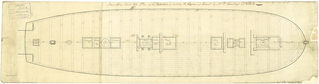
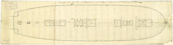
Here a picture out of NMM, the Cyrus of 1813 with planking details :-) XXXDAn
-
...hihihihihihihihi... As the lower deck of my other Victory will definitely still will take some time - in the Year 2525 - here a small in between meal. The usual start-up picture - everything as it is known to be 🙂 Where will this lead to? To a face, that only a mama is being able to adore - or a dafi ...hihihihihihihi...
-
In some simple words - I think the main mistake we mostely do is to consider the deck planking done with parallel planks that - as far as I remember - came up with the industrial mills around 1800 - correct me if wrong. The nibbing and all the other joints of planking meets waterway and so on looks completely different with the curved planks. So the waterway can be met without nobbing as it is a parallel curve. XXXDAn
-
Well done so far! I think for this scale, faking would be a much more appropriate way ;-) Here a nice version on a Airfix Prince. it is in german, but the pictures are sufficient I believe :-) 420 444 Also he gives a nice solution for the deadeyes a bit further on. Cheers, Daniel
- 110 replies
-
- 1
-

-
- heller
- le superbe
- (and 2 more)
-
Sharing is great - and big thanks to him if it was him who made me aware of the wonderful possibilities offered by the world of Tic-Tac :-) XXXDAn
-
And now something different - the difference ... ... the small irregularities in the bow do not bother me to much. From there do come the remains from the first picture, I replaced them by bigger plates. Still refined the corners ... ... and fixed missing nails. The false keel, first try with flattened 0,3 mm copper wire ... ... but this proved to complicated to assmble. Then better simple copper foil :-) Then still enjoyed some unusual views ... ... and brought back my small one into her normal position ... ... and had a deep breath as no bigger casualties had happened. Only the school table looks like was not glued ;-) XXXDAn
-
... doe, how to say ... ... I just looked - no touching involved ... ... but how did this happen ?!? Suddenly my sweet one found herself lying on the back ... ... and got the edges worked with the RB Riveter. Then changed the dermaroller from large-gauge ... ... to narrow-gauge. And here we go :-)
-
Oh you are scared of model part´s suicide?!? That is new, I better go to a psychiatrist with my dear shipdaughter to avoid more losses ... ... there is still enough V1.0 on her ... ... and V2.0 that were already redone ... ... and V3.0 that was also overcome ... ... and the V4.0 that ... ...hihihihihihihihihi... ... XXXDAn
-
... only a little bit ... ... Jan I am so sorry I lied to you ... ... wasn´t intended ... ... did not touch it - just looked ... ... came off by itself ... ... soooooo sorry ... ... ... XXXDAn
-
MAAAAAAAAAAAAAMMMMMMM, he did it again, and he lied ... XXXDAn
-
Fastening of the false keel
dafi replied to dafi's topic in Building, Framing, Planking and plating a ships hull and deck
Also one can see a lot of staples missing. The staples of the first keel were flush in the surface, so the slots are still visible if one has a close look. Those of the first keel appear to be closer than those of the second one. Also the ones of the second one have different lengths: Into the "true" keel and into the first false one. I was looking quite close, but still difficult to see a pattern. DAniel -
Fastening of the false keel
dafi replied to dafi's topic in Building, Framing, Planking and plating a ships hull and deck
This one ... http://en.wikipedia.org/wiki/John_Gault ... or this one ? http://www.greatdreams.com/blog-2012-2/dee-blog279.html XXXDAn