HOLIDAY DONATION DRIVE - SUPPORT MSW - DO YOUR PART TO KEEP THIS GREAT FORUM GOING! (Only 72 donations so far out of 49,000 members - Can we at least get 100? C'mon guys!)
×


dafi
-
Posts
2,426 -
Joined
-
Last visited
Content Type
Profiles
Forums
Gallery
Events
Everything posted by dafi
-
Matt it is! 🙂 XXXDAn
-
Not to forget, these instructions were done more than 45 years ago and base on the 1920 reconstruction. Thus said one understand the color "cadmium yellow" being indicated in the instructions. And yes, I have pictures of the ship in cadmium yellow as it once was 🙂 Yellow ochre, sunflower yellow or yellow ochre blended with red and white (latest result, but sure not last), also feel free a bit for your own taste. The correct shade of color will surely never be revealed as even "newer" ships like Bismark there are raging discussions about this topic ... XXXDAn
-
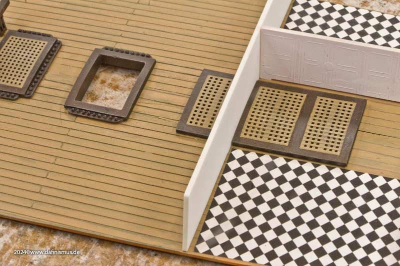
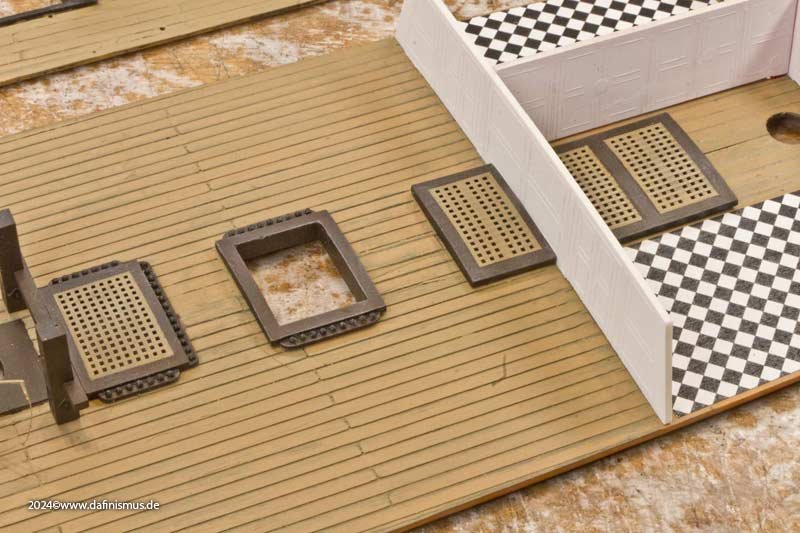
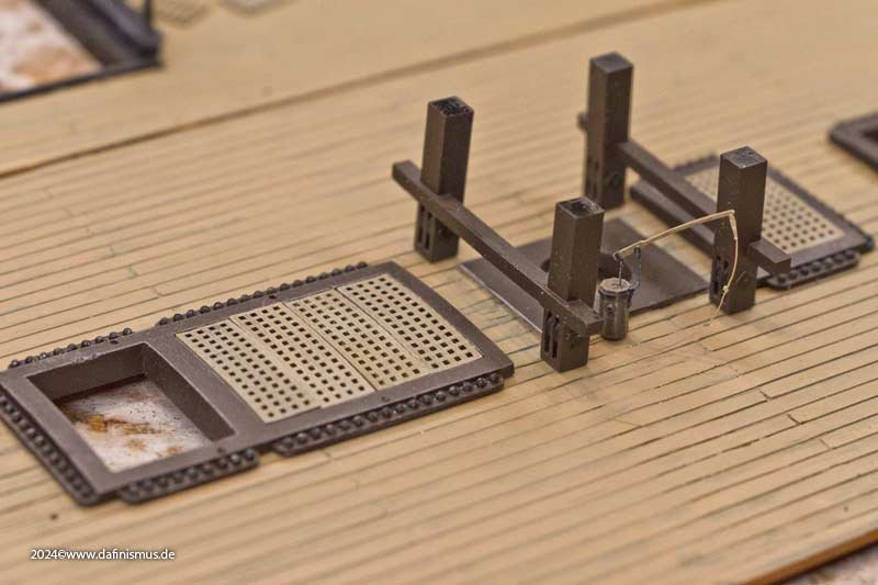
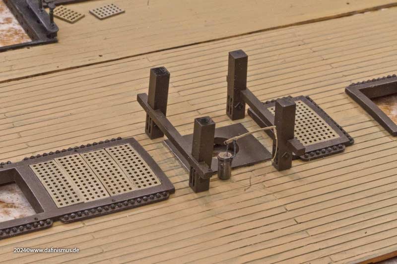
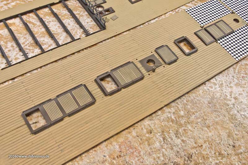
 And this was the result of what I was able to complete during the public crafting session at the trade fair. The gratings also have the correct different thicknesses for the longitudinal and transverse battens on the underside. The admiral's quarters area was given a chequerboard floor. Here you can also clearly see the rollers of the bitts in the deck below. And the forecastle looks much more structured and tidier too. Well, that's it for now 🙂 XXXDAn
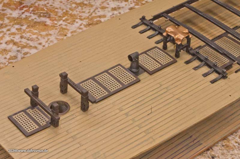
-
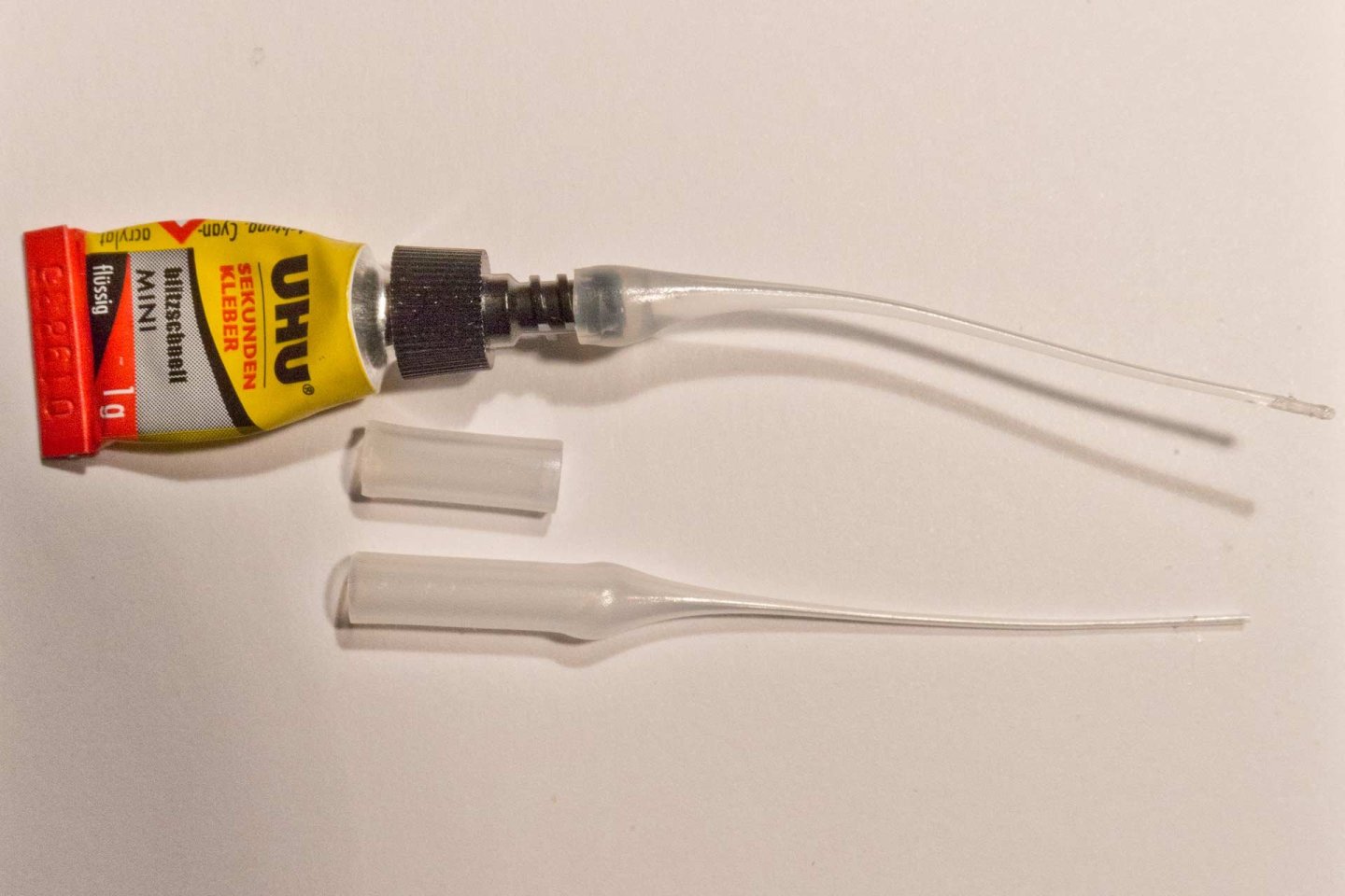
And for really tiny applications these applicators are unbeatable. They do not need to be closed and stay open for a long time. If closed, just cut off a quarter of a millimeter and its fresh again. Only safety hint: Start pressing gently until the air bubble rises. If it does not rise the tube immediately it is closed and needs to be cut. And if you cut after having applied too much pressure it will release quite a bit of glue until the over pressure is released. Otherwise this cheap things reduced the amount of wasted glue immensely! XXXDAn
-
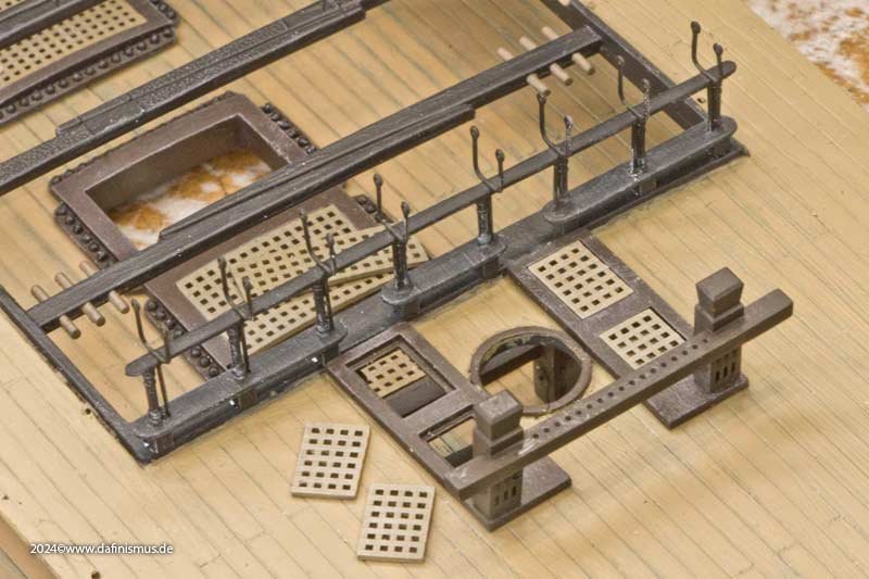
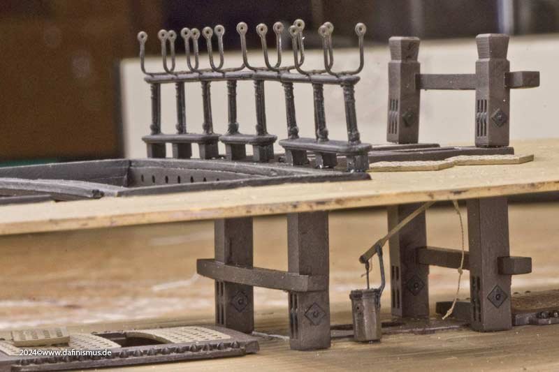
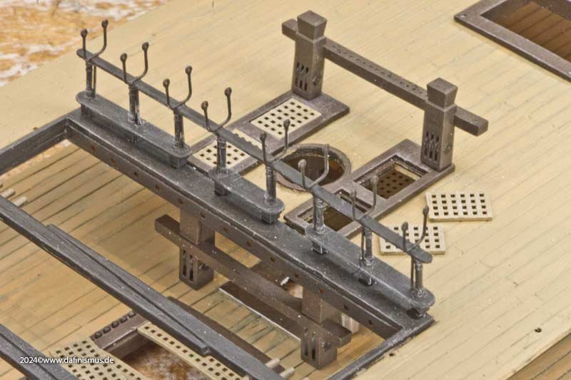
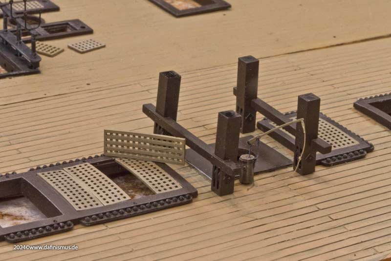
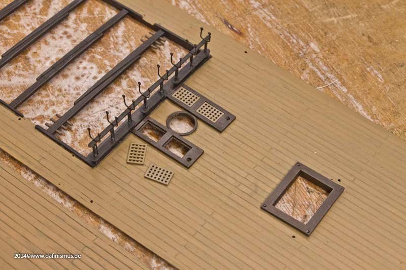
Oups, and I forgot to tell you that before the planned mess, we first had to test fit the new parts. Non-existent openings in the admiral's quarters were marked... ... cut out ... ... and adjusted to the bulkheads. The coamings and gratings were also adapted to their openings, or vice versa. And at some point, the upper battery deck was completely covered with coamings. The same procedure was followed for the forecastle and aft deck. The coamings are not as high here, as there were open decks underneath. In the area of the main mast, the gratings can be taken out, as there are some ropes leading to the bits in the deck below. This makes it easier to belay them. I also installed those bits and, as a little treat, a new hand pump was also installed there. Then the coamings were given their colour. The gratings were then masked off and painted light brown, then inked very thinly with black ink and brushed with white. And then there was the slave labour: gluing in the cannonballs... ... and securing them on the underside with thin-flow superglue. Finally, I doped the railing with the net holders... ... and add some thickness to the gangway with white Evergreen on the underside ... ... and this part of the task is finished.


-
🙂 🙂 🙂 XXXDAn
-
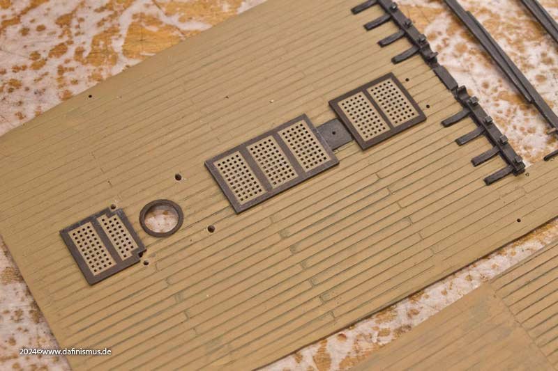
Next, I had to come to terms with the not *quite* correct planking pattern. A few beers later, I was fine ... Then I realised that the plank gaps were much too wide and would be far too prominent for my liking when filled with paint or wash. So I came up with the following plan: I sprayed the deck black ... ... and then scraped off with a blade so that the black paint remained in the depths like preshading. As always with my best plans, it ended up being a big mess. Then I tried out different shades of brown, both solvent-based, acrylic and water-based, in various opacities. It resulted in a pretty patchwork. The forecastle in particular was quite colourful ... ... which is why grey tones were used on the gangway. But what can I say, I really didn't have such a grimy deck in mind. So I sprayed it again and stripped it off again. In the meantime, I had remembered the other moulded parts, especially the gratings, which I had tuned to wood. That was the specification it had to match. And even though there are usually no major colour differences in the wood on original decks, except for traces of moisture, preshading with black prevents it from looking too much like a painted steel deck. You just have to throw your imagination a few little treats now and then to keep it happy. It was just a matter of finding the right balance. So I applied three glazed coats of paint until the black was only very faintly visible. Interestingly, the plastic of the upper deck was a light beige, while the lower deck was reddish brown. This was easily remedied by applying a grey glaze under the brown glazes. This technique also brings the area under the forecastle, which has no plank engraving, to life so well that engraving was not necessary and simple pencil strokes can substitude the engraving. I think that, given the limited visibility of this area, this is a good effort-appearance ratio. So, quickly in with the printed parts... ...and take some beauty shots.


-
Before heading to the trade show, things were naturally crazy for me – splinters were flying once again. One of the things I wanted to show was a comparison between the original kit parts and what you can actually make out of them. To do this, the decks had to be prepared. First, the old gratings had to be removed. Then the good parts of the deck were protected with gaffer tape and the old coamings were sanded down with a coarse file ... ... and the remains were removed with a blade ... ... or helped along with a fine file. For the finishing touches, I sawed a batten to the right width and covered it with sandpaper, which allowed me to achieve a nice even surface. Since the new coamings are also supposed to cover the thickness of the decks, I had to cut larger the openings of the companionways a little. A red pencil line serves as a mark. This was trickier on the upper deck, as the deck is not divided in half. But here too, I first had to cut out the grating ... ... cut out the coamings with the flat blade and finish them in the same way as the lower deck. For the wide openings at the rear with the thicker coamings, I made a 45° relief cut with the scalpel, which meant there was less material to remove horizontally. This made it much easier to work with the blade. And then again, enlarging the section by the width of a pencil. For this exhibit, I deliberately chose not to use a purchased wooden deck or one built one like on the other model, but to experiment with what could be achieved with paint. Now it was getting exciting ...


-
Captain Dafi, personal logbook, addendum: Recently, it was time once again for public tinkering at the game fair in Stuttgart / Southern Germany. I had brought quite a bit of material with me again. A little reminder of Èvian 🙂 And my Soleil in full sun—simply ROYAL! One of my topics was the comparison between the parts that come from the kit and what you can make from them. Here is a comparison of the two upper decks. And as usual, there was plenty of delicacies to enjoy: pumpkin-sweet-potato-carrot-potato-ginger-soup special recipe dafi — yum! Enjoy, Daniel


-
I always understood that this was much more a french feature and the english preferred the bolts not running through but being secured by a heavy wood thread in the frame? Could this be correct? XXXDAn
-
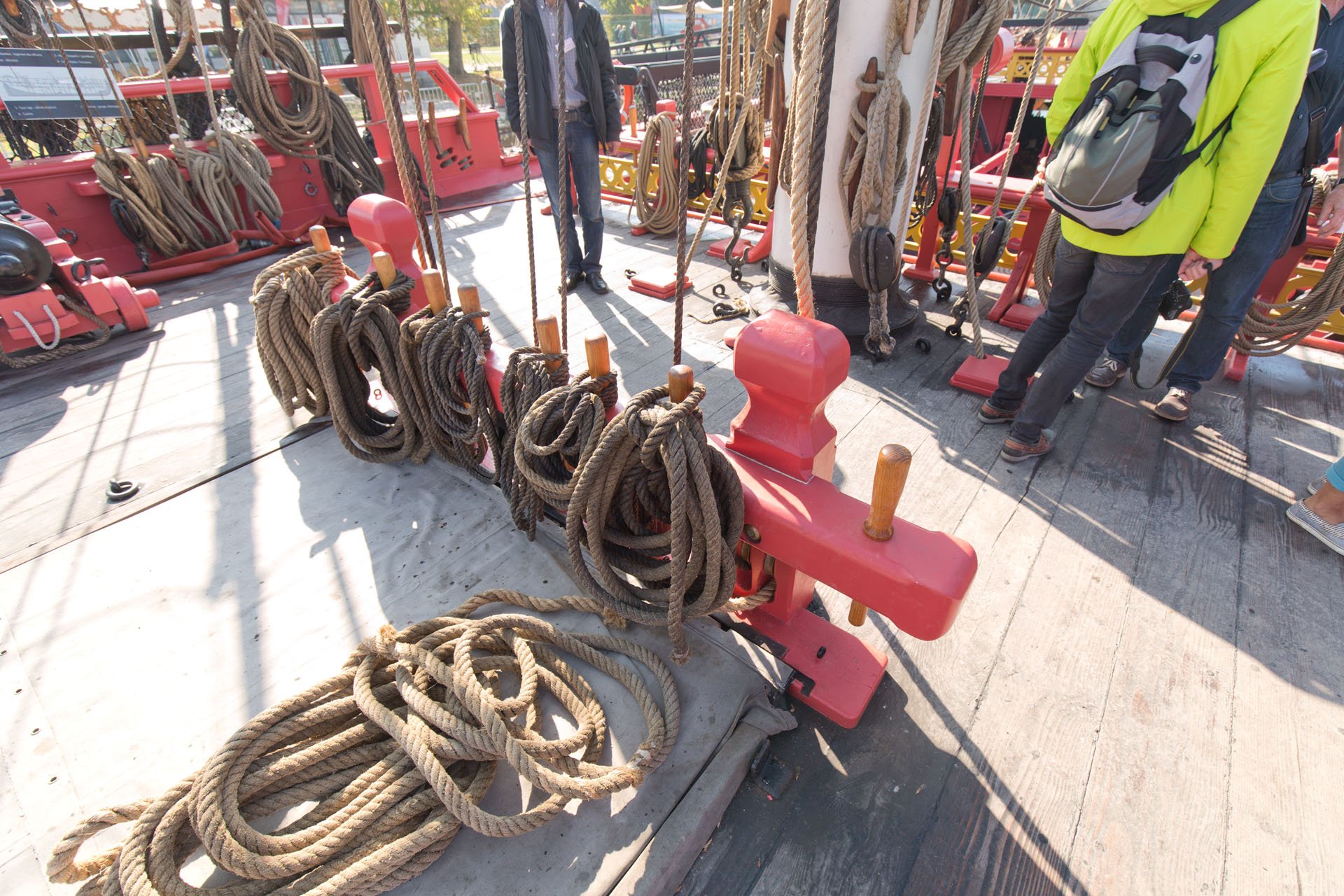
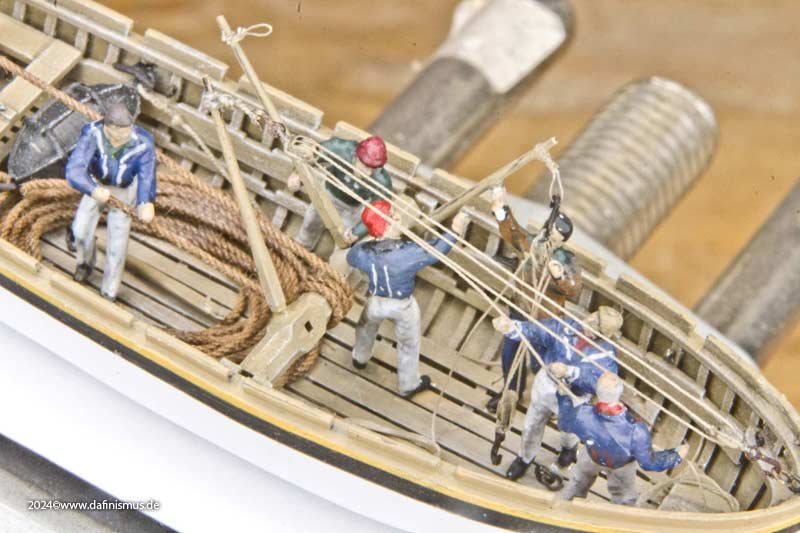
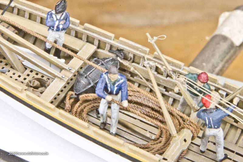
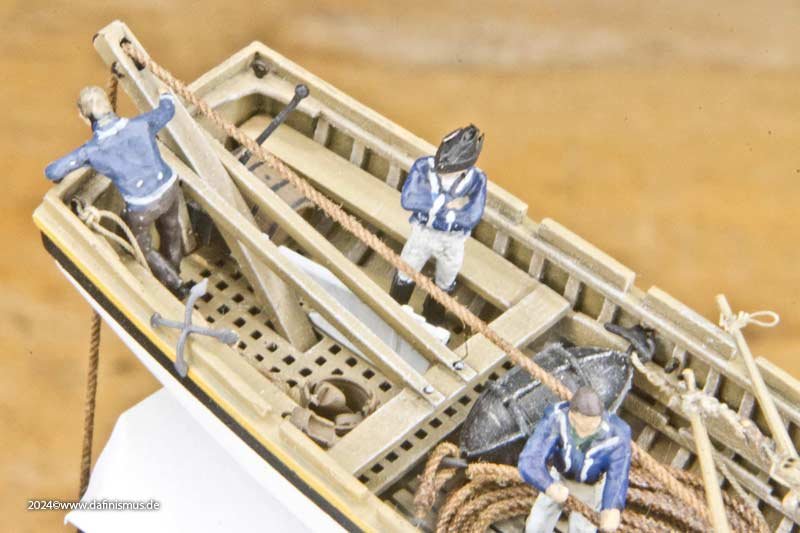
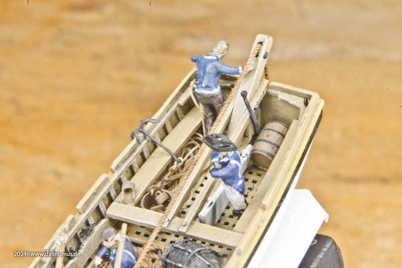
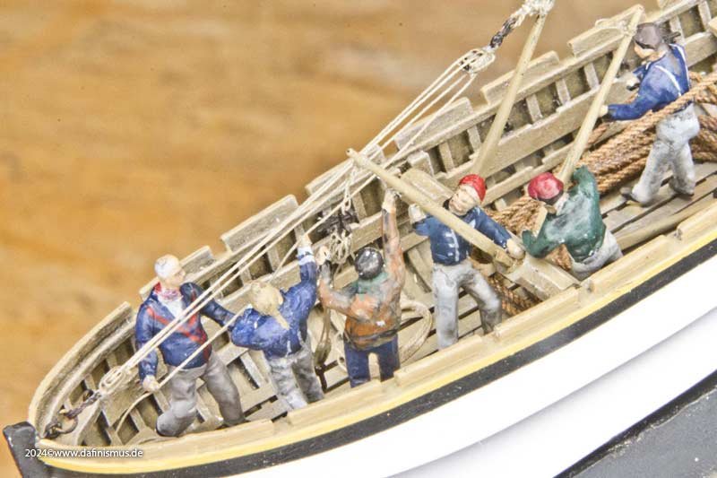
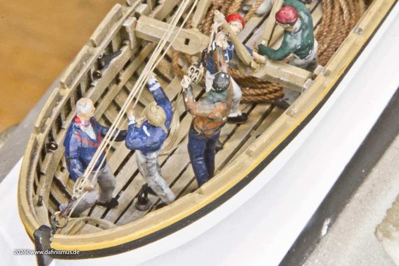
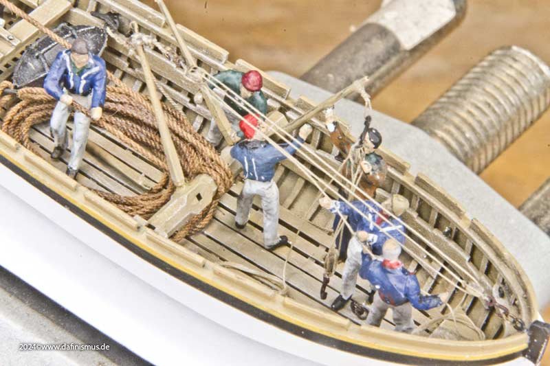
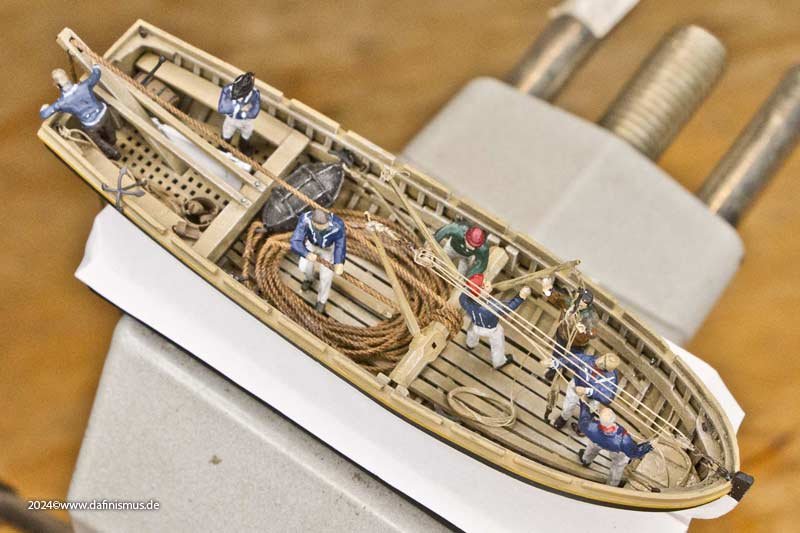
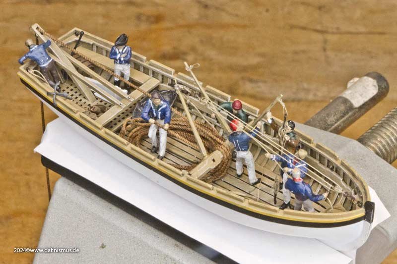
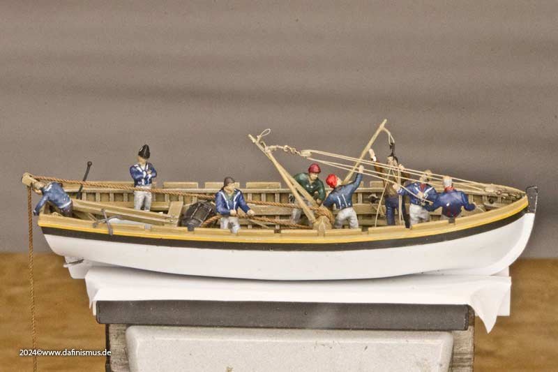
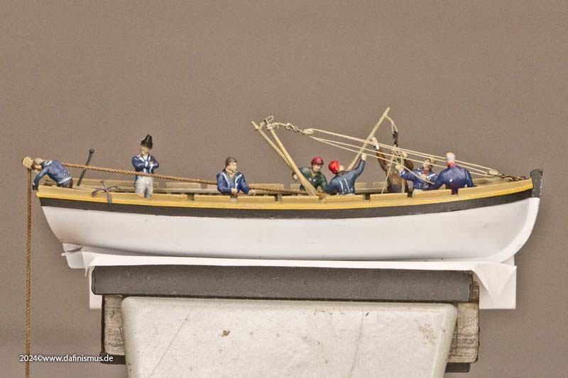
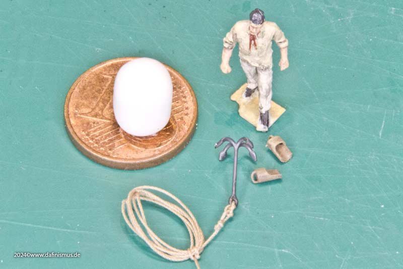
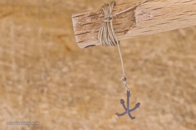
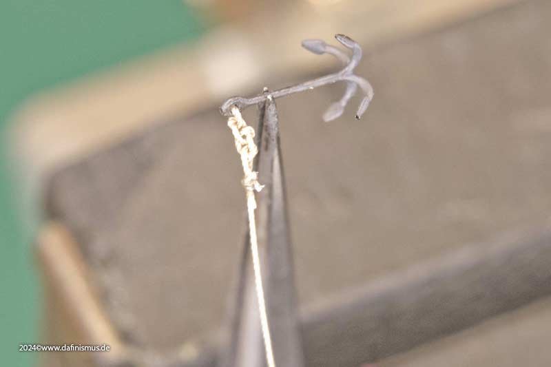
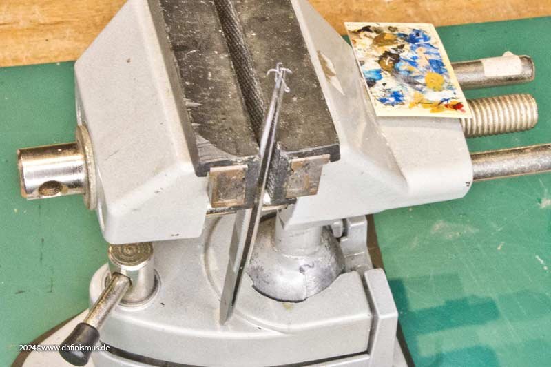
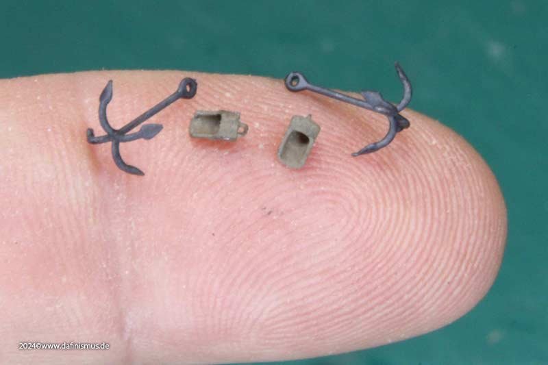
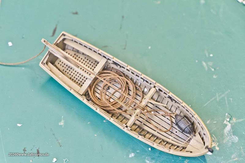
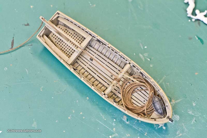
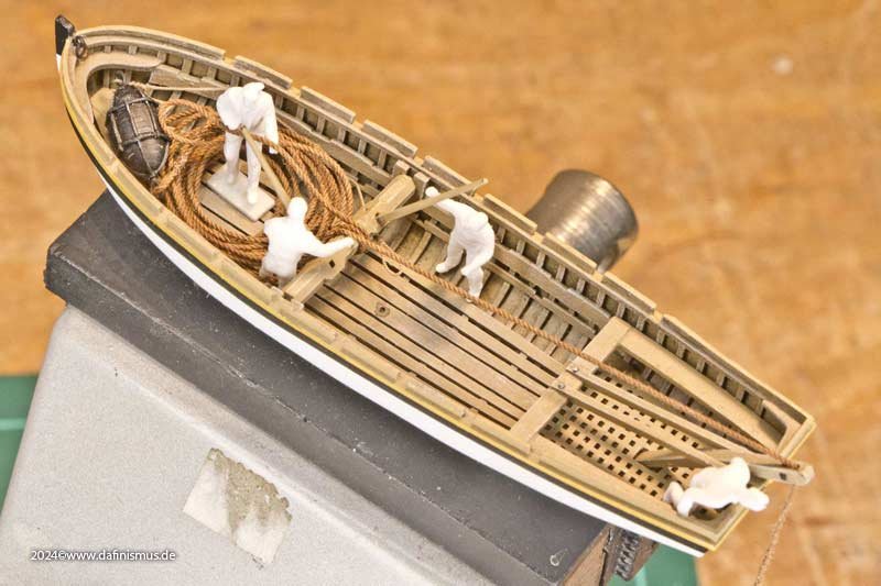
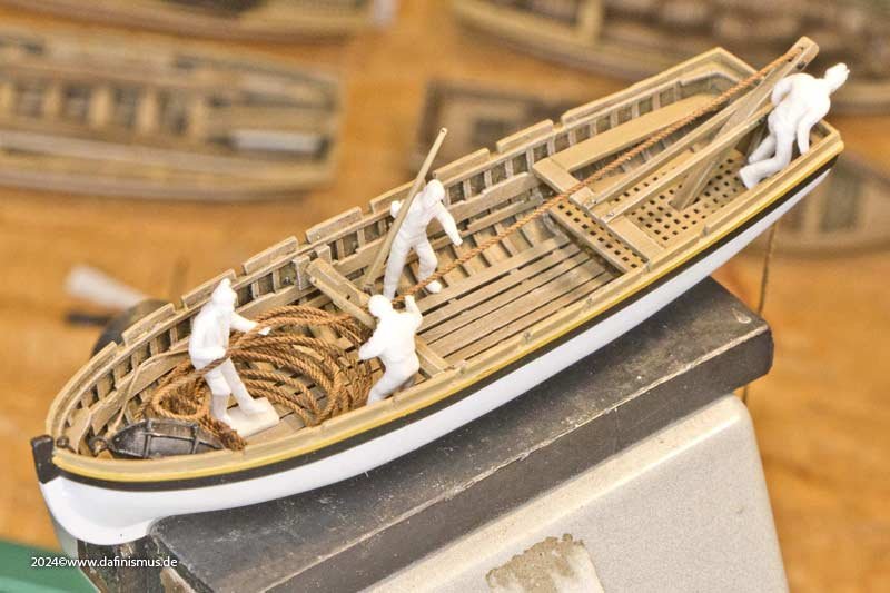
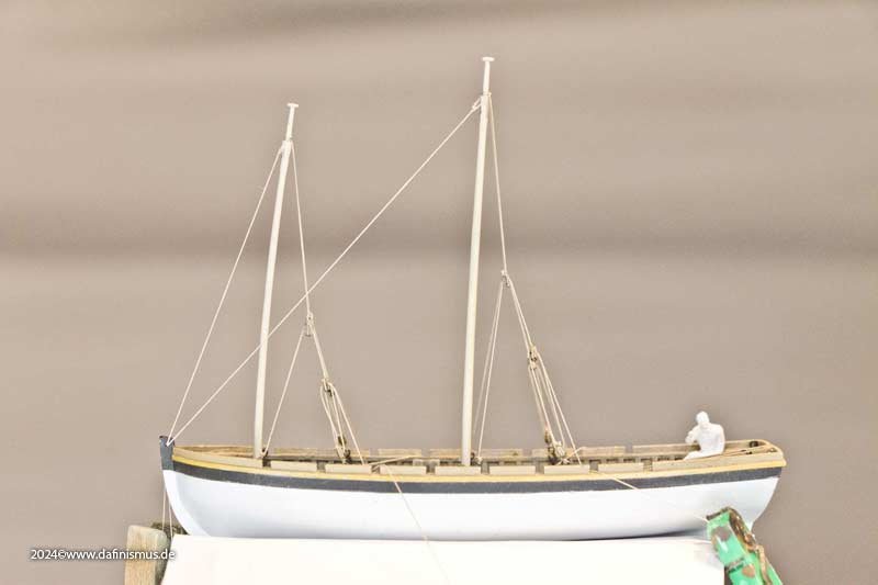
I was in model-building deprivation, with no time to do anything and not even to document what I had already built. The version of the Launch with sails has to be stored in the back for now, as martens have damaged it by chewing on the sails ... That's why I continued with the version equipped with a davit for anchoring and fishing. Here some pictures last stage. First, there was the question of where to put the cable that had been hauled up. Instinctively, I had stowed it in the bow during the first test. But in order to attach a pulley to the capstan that can only be attached forwards to the stem and the cable accordingly had to go to the rear. So I decided to store it in the middle of the boat, which is also better balanced, and you can see that this is a good solution. But first, a little bit of small stuff, which also makes a difference http://www.shipmodels.info/mws_forum/images/smilies/icon_wink.gif The pulleys are pre-assembled; this one should hang loosely, so I shaped it with wallpaper glue. The grapnel anchor and ladles have also arrived. To tie in the anchor rope, I clamped a pair of tweezers in my vice. And then I built a nice bunch with the rest of the rope. And here it is the small menagerie. And now it got pleasantly exciting, but see for yourself... While two lads secure the pulley, the capstan bar is being changed on the other side. The lieutenant keeps a watchful eye on the whole process, while one man checks to see if anything is happening at the back end at the cable. In the middle, one man holds the cable taut and clears it neatly. That setup certainly wouldn't have worked with the rope at the front in the bow, as crowded as it already is there. Cheers, Daniel
-
I always would like to warn to take the museum ship/reconstruction in Portsmouth as a reference. Actually that was the hardest learning for me to ignore this wonderful exhibit on my trip down Victory roads 🙂 Not moaning or beefing around at all those people that were and still are keeping her alive untill today, but for ressources and other reasons it is far off being a reference. It is a wonderful inspiration, it really is, but not more. Showing the treenails or the covers for the nails in the model? Simply a question what one wants to achieve with the build. Do you want to show the construction principles - then show the nails. If you like a realistic view omit them. Simply a personal choice. All the best, Daniel
-
Wales
dafi replied to -Dallen's topic in Building, Framing, Planking and plating a ships hull and deck
But it is very tricky to take everything past ≈1860 as a referenece (if not for that very special time) as the ships were heavily reworked with view on the costs and the fact that those ships mostly went into harbour duty. There is not "one" place for the wales as it followed the "fashion" of the times and the needs of the ship. As the internal structures were always improved, so were the outer parts too. If I recall well, the wales on Victory changed place during the great repair in 1803. And in ≈ 1860 they were completely replaced by a smooth and cheap planking as only harbour duties were done. And even today (or at least before the last restauration) Victory´s wales were just a fake by being much thinner than the looks suggested and being invisibly augmented by steel bolts to give some distance to the frame ... XXXDAn -
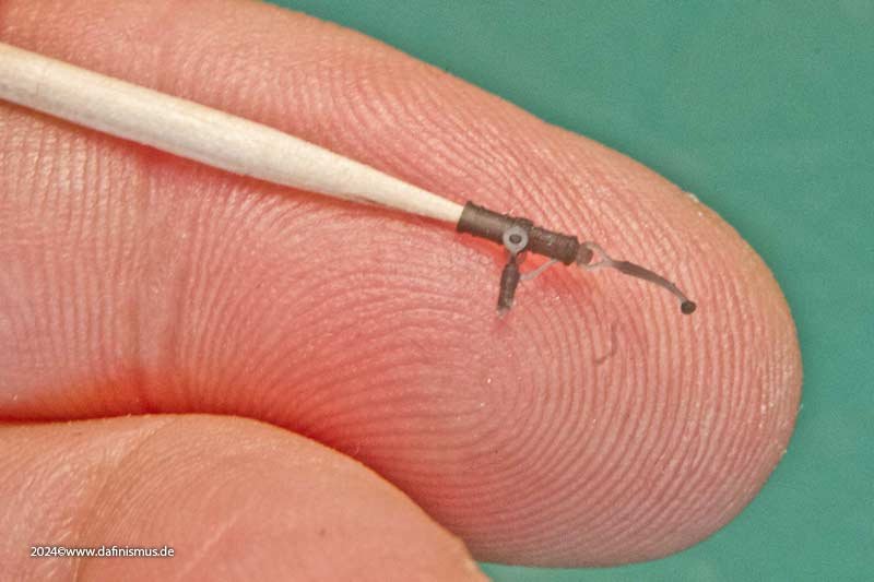
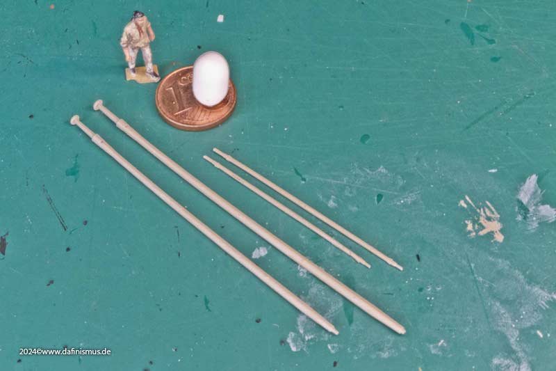
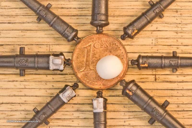
Thank you for all the thumps up, as always very appreciated! And I am always delighted by the fine structures that are now possible in printing. Once again, parts whose diameter is half as wide as my papillary ridges, these are some of the finest parts of my products 🙂 XXXDAn
-
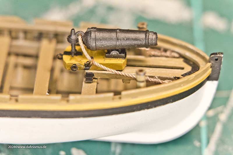
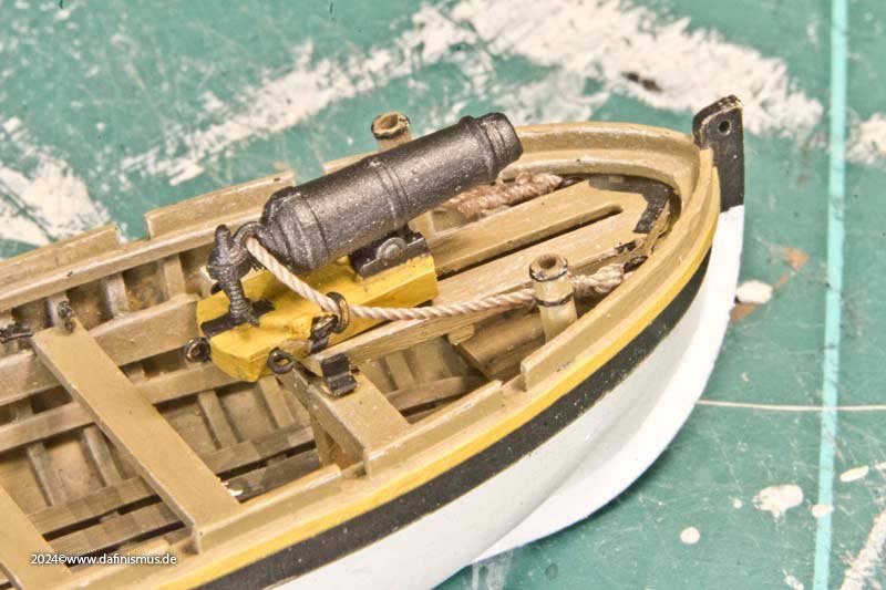
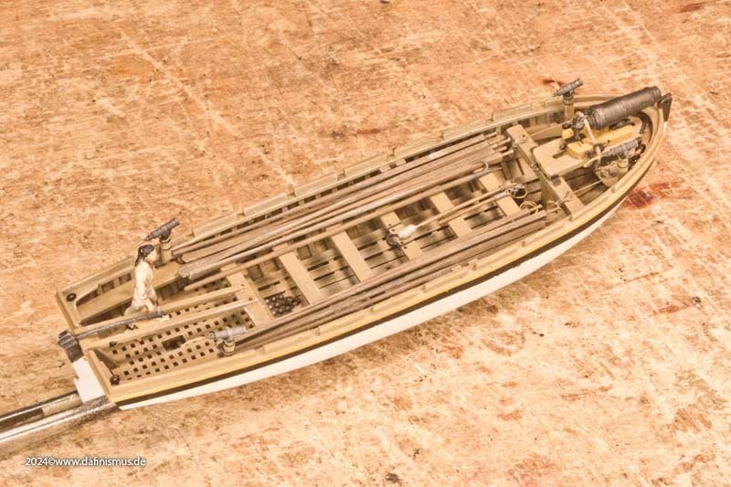
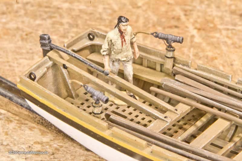
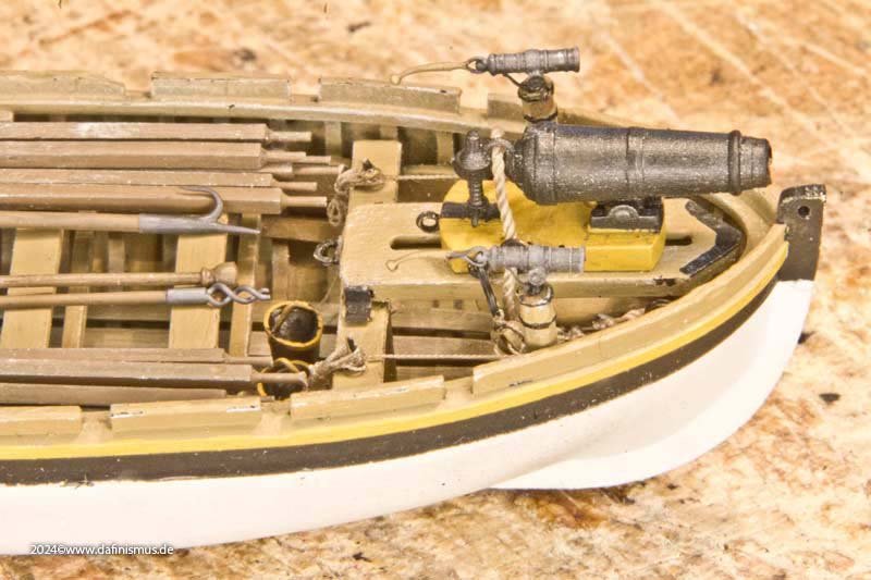
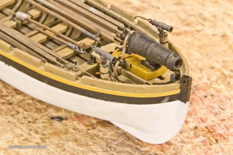
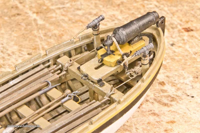
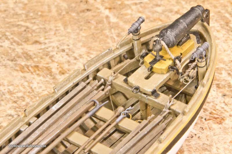
As I have wrecked the sails, there is a forced break at this point to ‘reweave’ them. Since my day-to-day business leaves little time for this, it is taking longer than expected. Therefore, I am continuing with a rowed version as an interim action to build. According to the armament list, the Victory had a 24-pounder carronade for the big launch, for landing operations and similar tasks. It is time to continue with this little vignette. To this end, I have acquired a 24-pounder from my Constitution model, removed the first thwart, reinforced the second one, and already have a passable support. I have also added the swivel guns from the fighting tops of the my Constitution. First, I checked the length of the breech rope. The green underlay is good for rigging the small blocks, as you can push two needles into it as holding points. The blocks themselves were slotted into the vice as already described. And then it was finished http://www.shipmodels.info/mws_forum/images/smilies/icon_smile.gif The tools for the carronade are already included, shortened in comparison to the other guns. The cannonballs are stowed deep in the boat in the rack. All that's missing are the small salt boxes for the powder cartridges and a toolbox. Enjoy, Daniel
-
Mara thread - what colors do you use for fabricating ropes
dafi replied to Sterling59's topic in Masting, rigging and sails
I still wonder if this block is a Stay Tackle Pendant / Fore hatch Tackle Pendant. Also it appears as it has an iron thimble around the stay. Often a sign that it should slide up and down. But there is a small seizing just beside that seems to block it - also what about the snaking in between the main and preventer stay. By the worming this block is attached at the main stay. XXXDAn -
Mara thread - what colors do you use for fabricating ropes
dafi replied to Sterling59's topic in Masting, rigging and sails
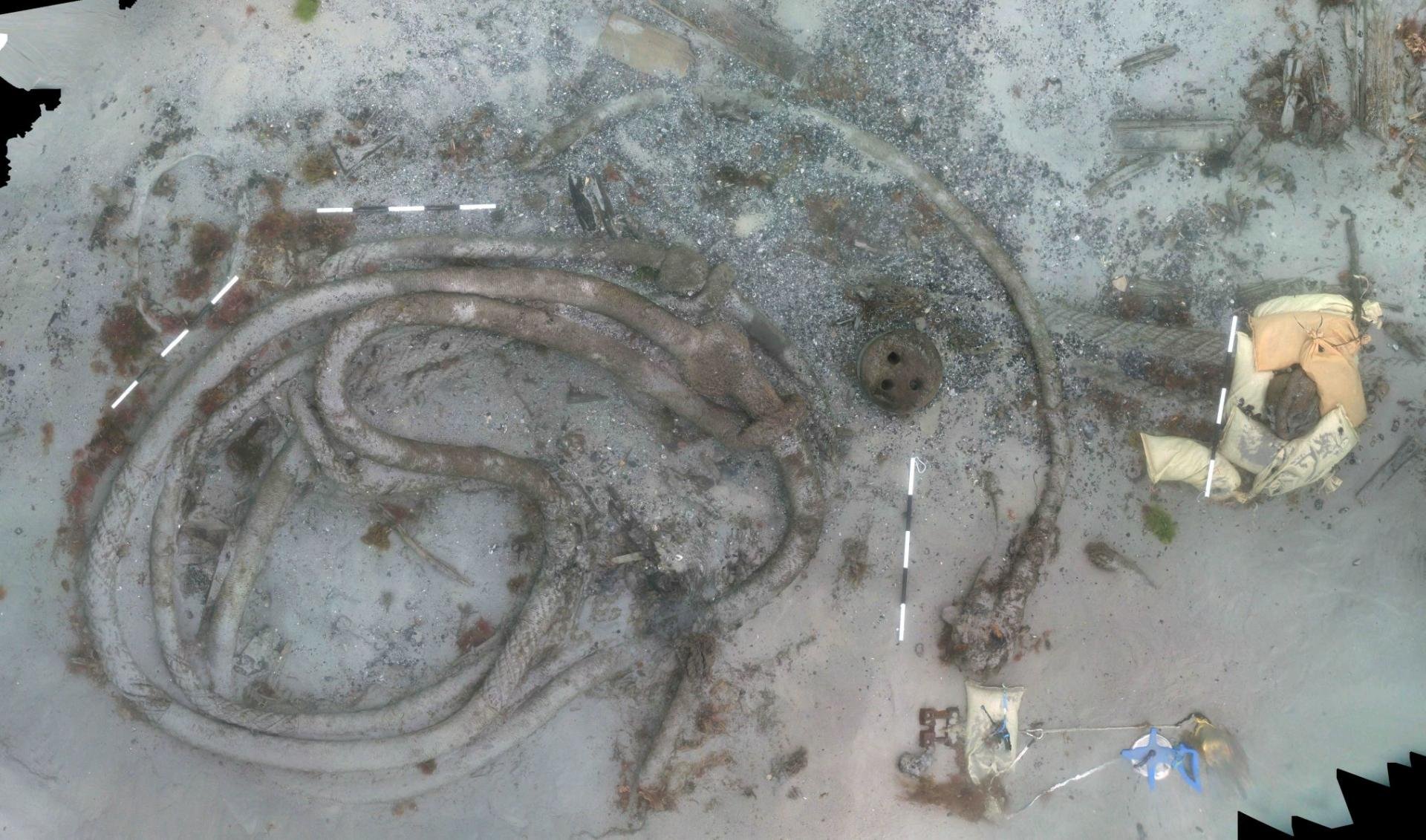
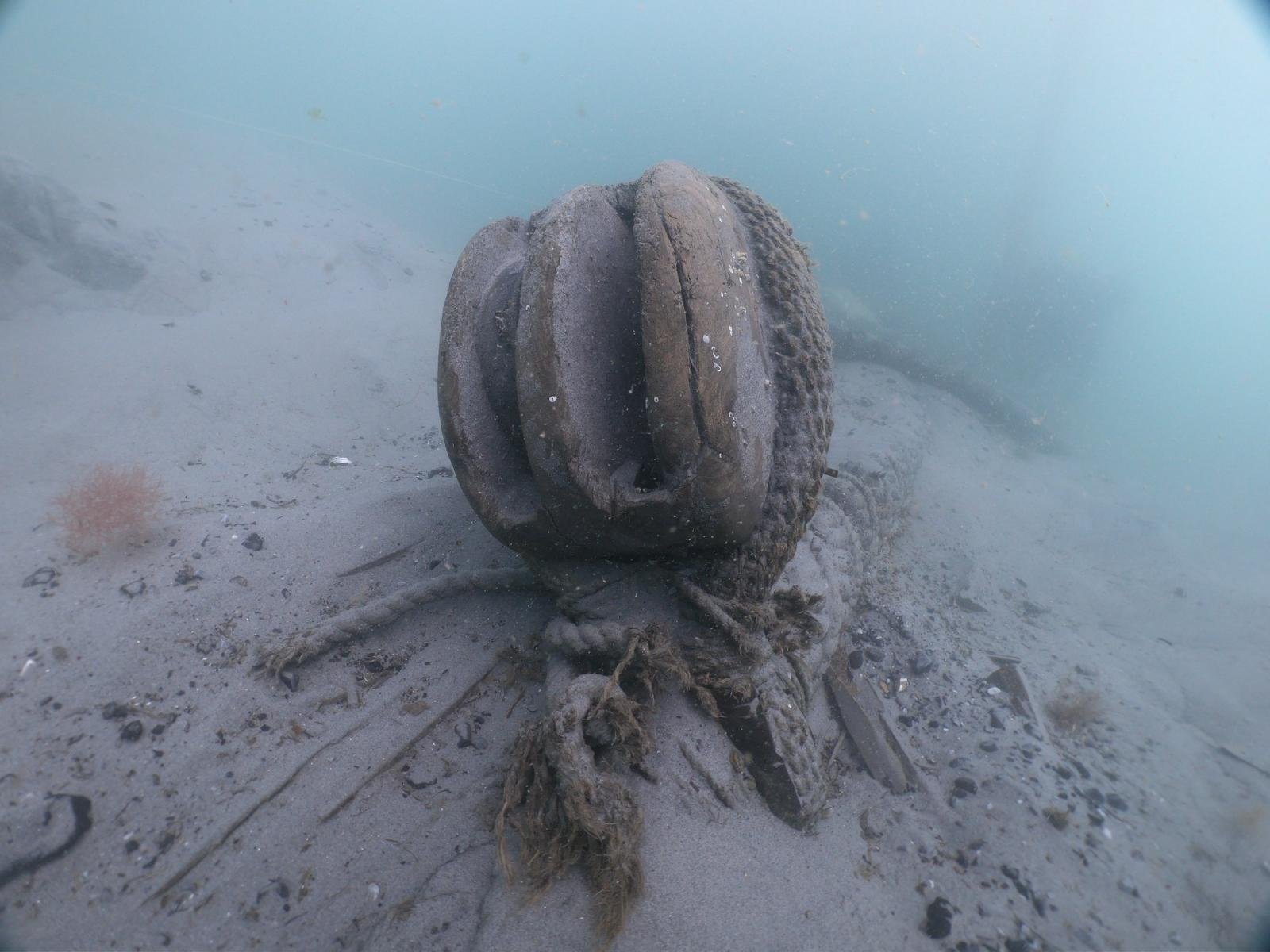
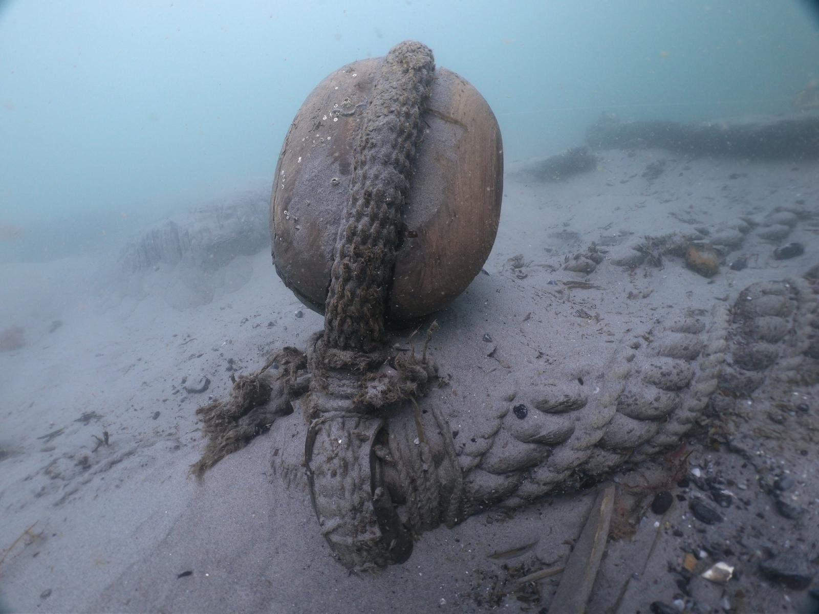
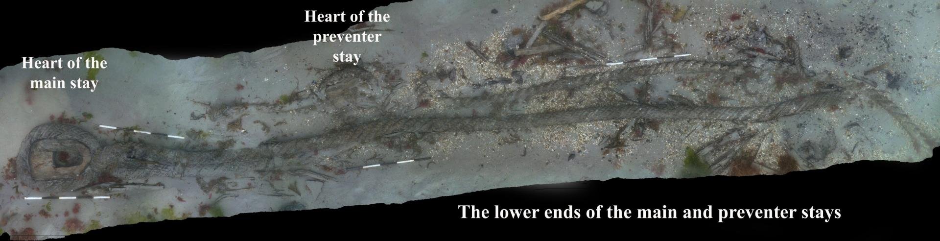
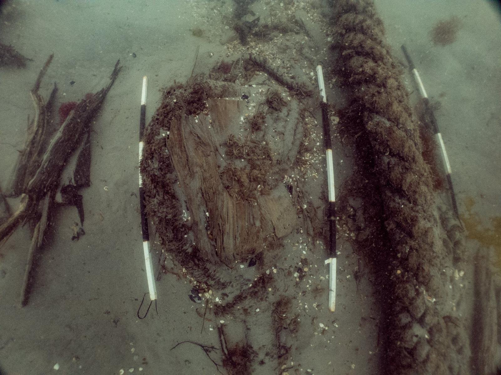
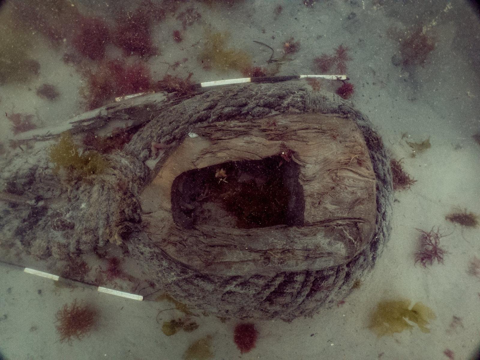
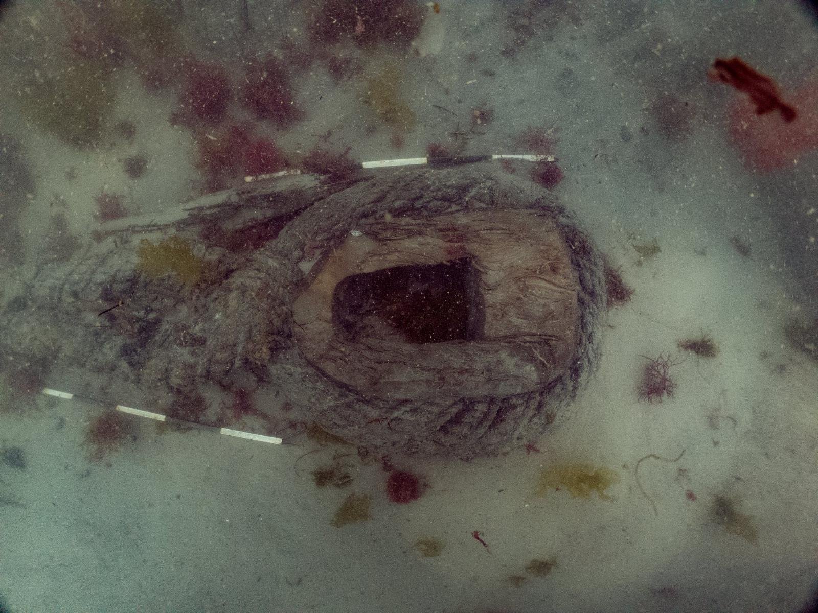
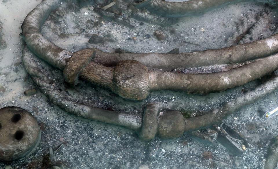
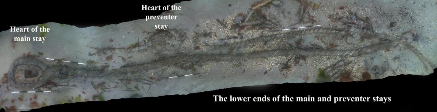
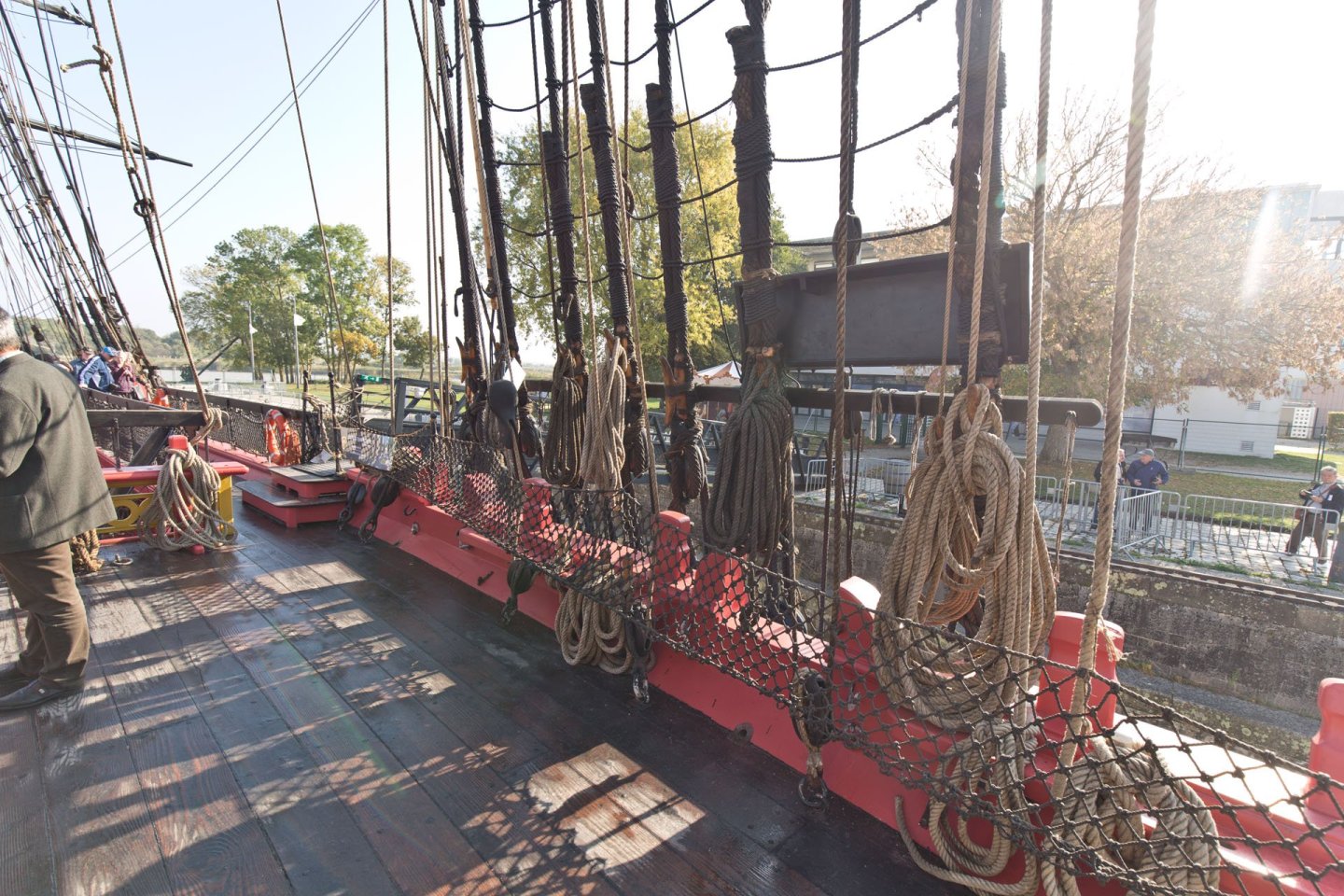
Just to support Chuck´s and Greg´s observation: When I started to hit the french forums, I was surprised them not doing the "usual" diffentiation in color inbeteen the standing and running rigging. Even more they were surprised that we or better I did. Eversince I orientate myself more on the style I saw on Hermione: different colors due to different level of tarring and also different bleaching by sun and salt. To the question if parts are wormed but not served I would like to show you the pictures of Invincible´s stays, nice to see the different worming, serving and the differences of stay and preventer stay 🙂 The mainstay wormed the whole length, served around the masthead up to the mouse, the preventer no worming along the length but wormed and served around the masthead. All pictures taken from the Facebook site of Invincible wreck. Enjoy! XXXDAn


-
Mara thread - what colors do you use for fabricating ropes
dafi replied to Sterling59's topic in Masting, rigging and sails
My 27 cents as for the color, as seen at Hermione: 50-thousend shades of brownish grey 🙂 No one is alike the other and even the shrouds are not completely black 😉 XXXDAn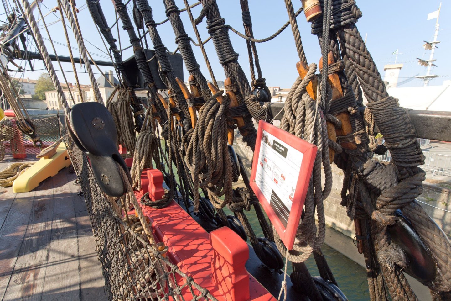

-
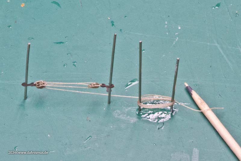
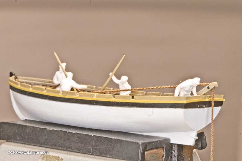
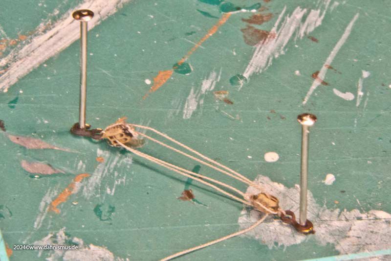
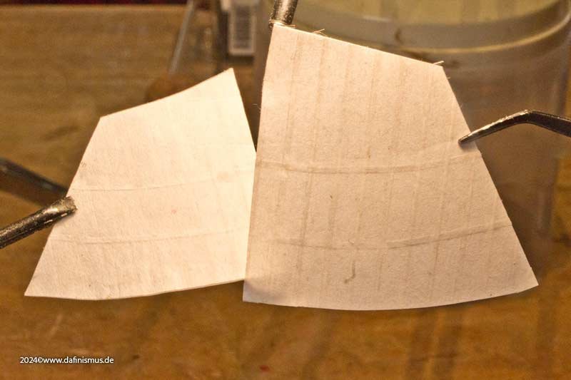
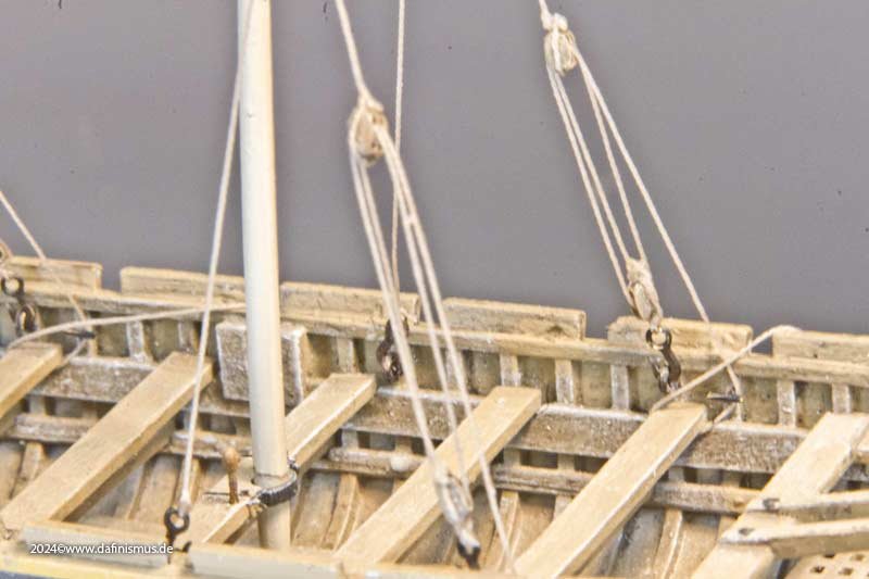
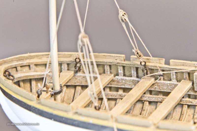
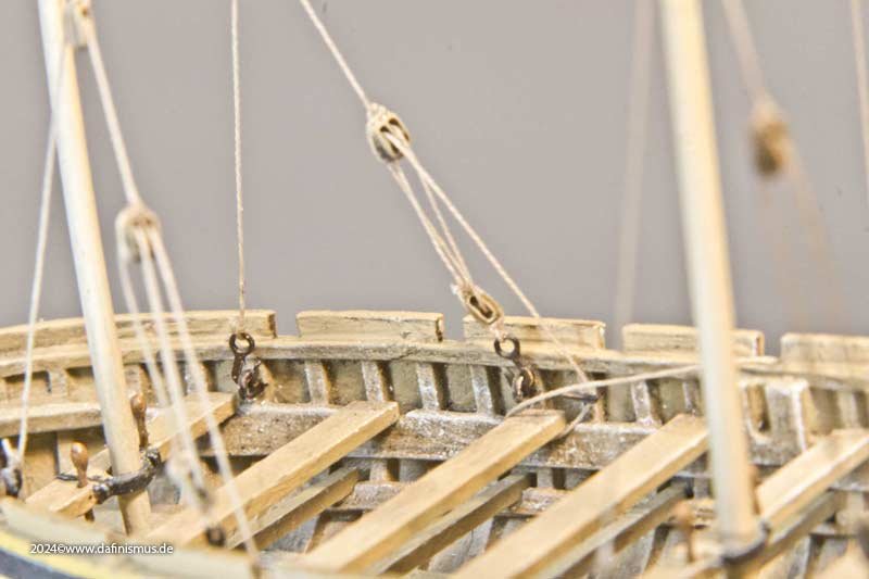
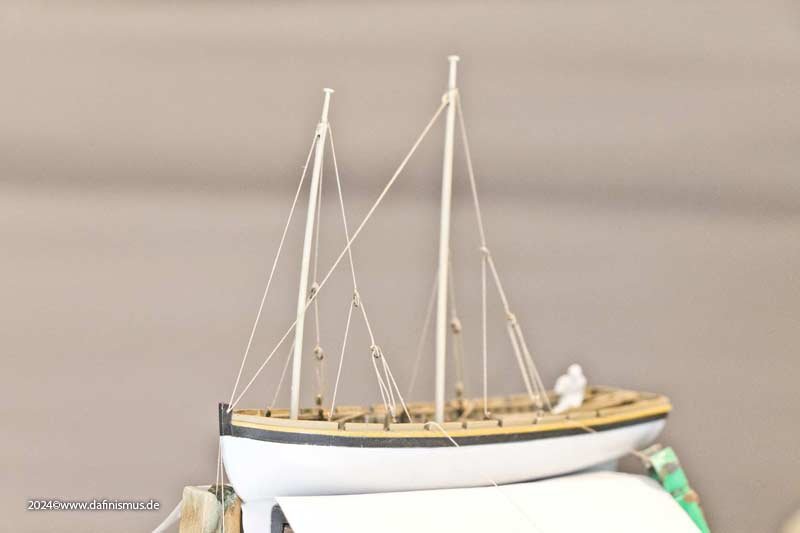
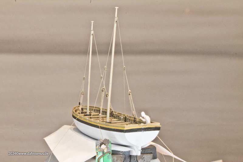
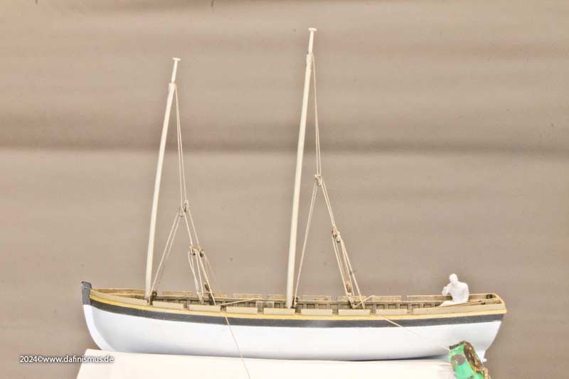
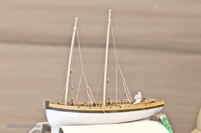
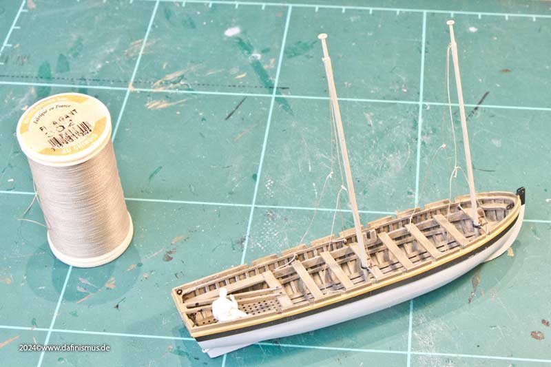
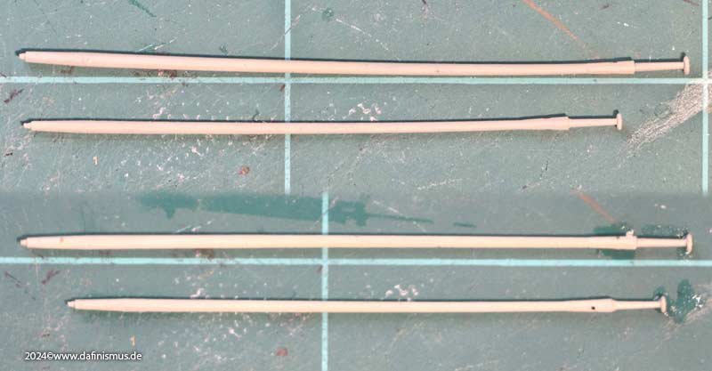
Time to continue with the big launch. The masts have been redesigned, with details taken from Steel. I keep noticing that thin printed parts such as oars and masts warp after painting. See the upper half of the picture. After a quick dip in hot water, they are straight again, see bottom half http://www.shipmodels.info/mws_forum/images/smilies/icon_smile.gif I simplified the rigging of the launch and combined various sources. As with the Hermione boats, the eye bolts were no longer attached to the top of the gunwale but underneath on the frames. It looks much clearer. Here is the first dummy rig with the newly positioned attachment points. Once rigged, it looks like this. I actually wanted to work without stays, but due to the stubborn rigging, this is hardly possible without curvature. The mainstay should then of course lead to the foot of the foremast. Here are the attachment points in detail. The running end is wrapped around a cleat, but not yet stowed. And the sails are also waiting to be processed http://www.shipmodels.info/mws_forum/images/smilies/icon_smile.gif XXXDAn
-
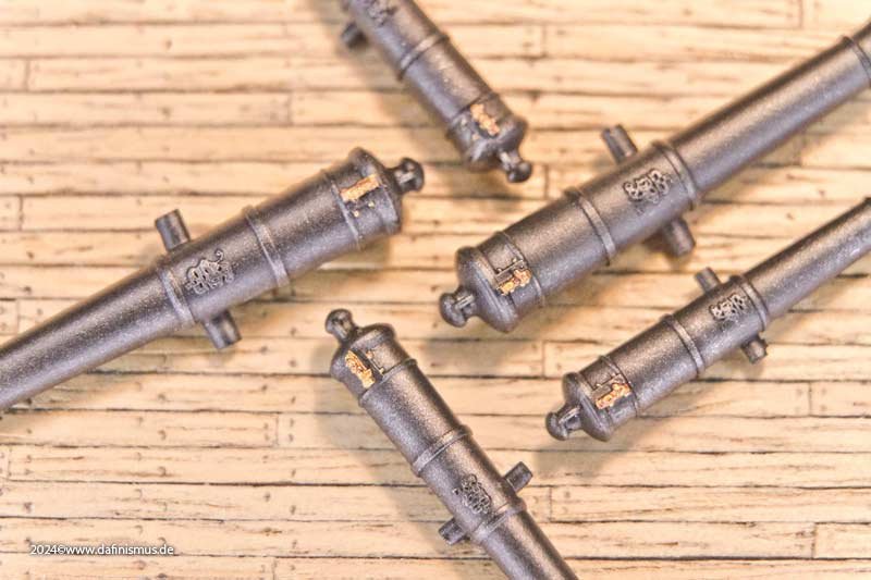
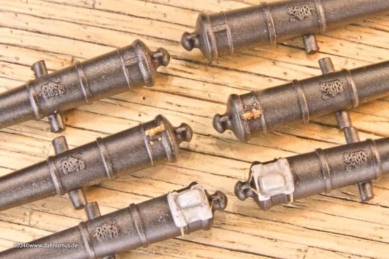
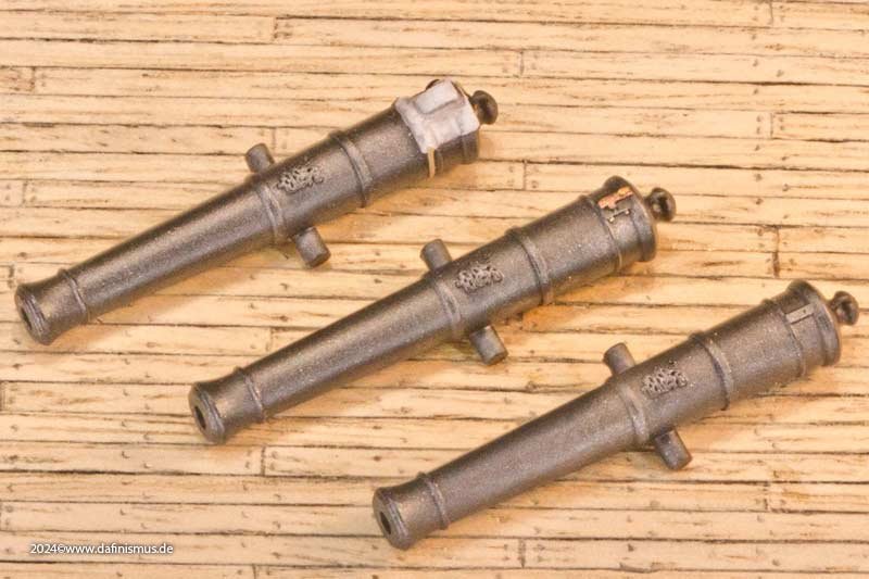
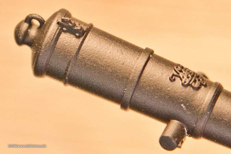
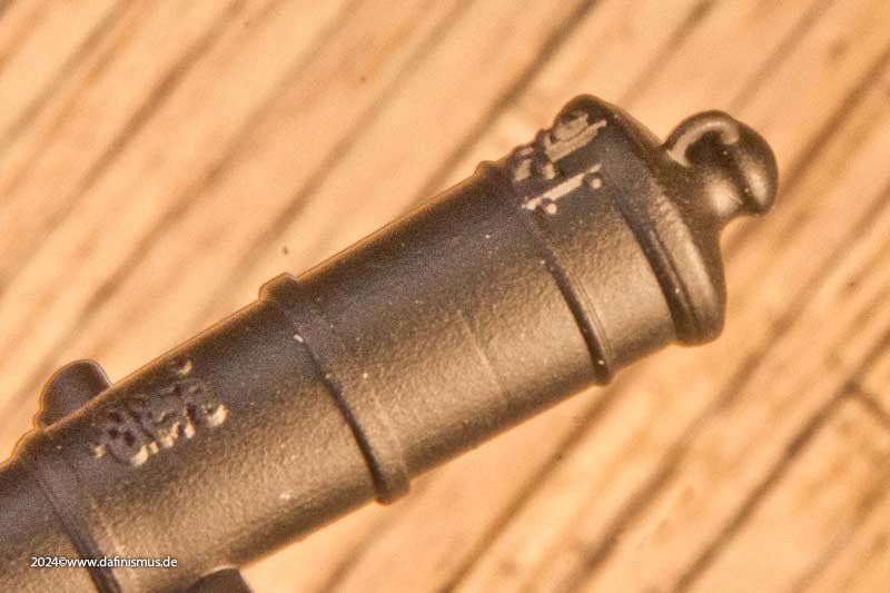
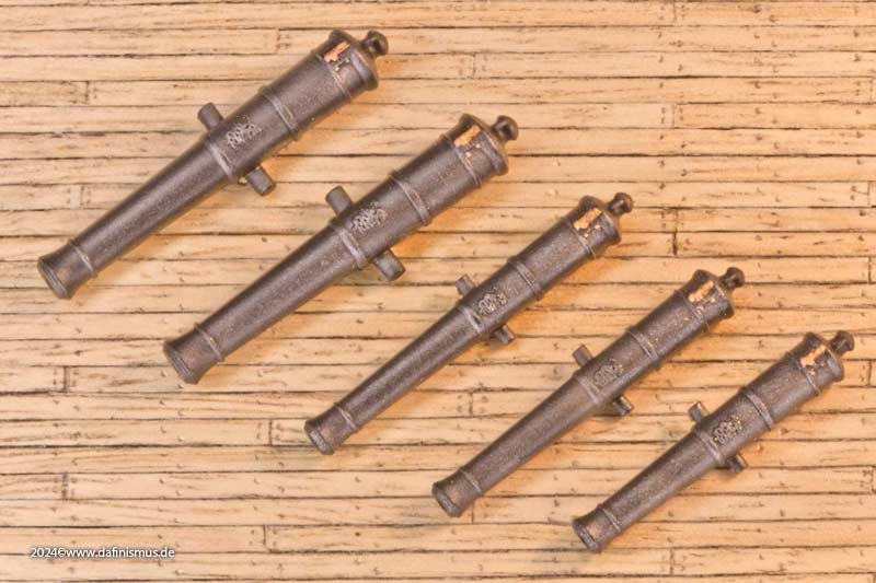
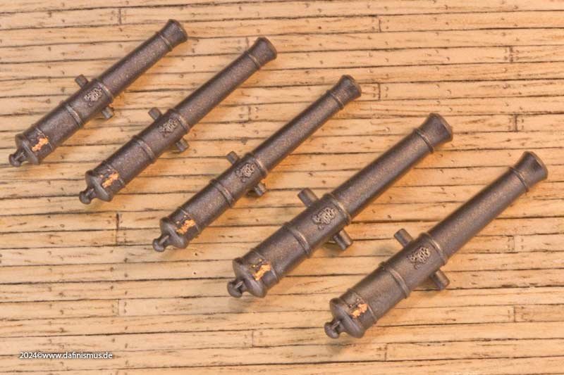
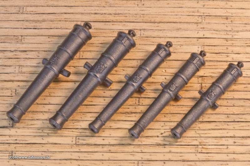
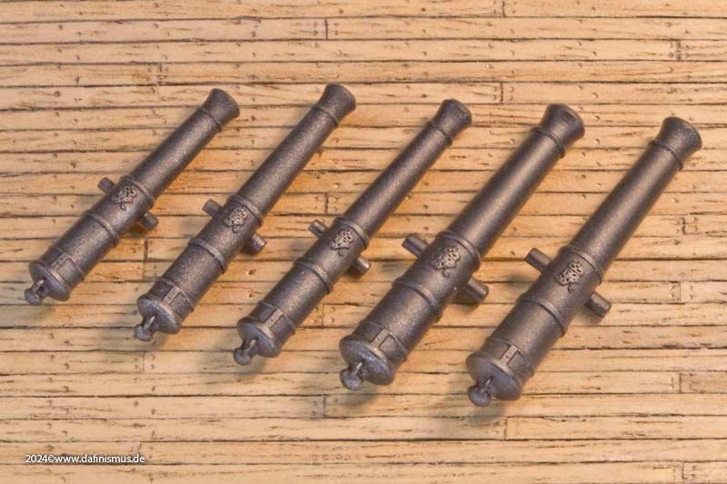
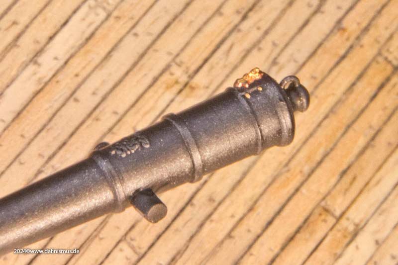
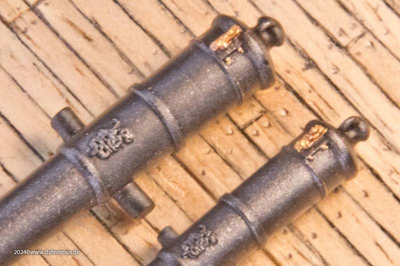
In the meantime I was working a bit on the big guns, here are some samples. More on that adventure here :


-
I had once an analysis to the "3 feet below the yard". It is measured from the top of the yard in my opinion, other points of taking the measure do make no sense imho. Short Executive Version: The simplyfied definition "3 feet underneath the yard" would possibly read on the working basis like this: Stirrup 3 Feet long, with enough overlength to do 3 turns around the yard and nailed to the top of the yard. Hangs behind and underneath the yard. XXXDAn
-
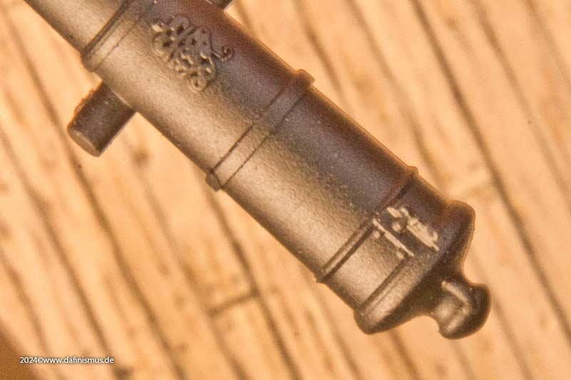
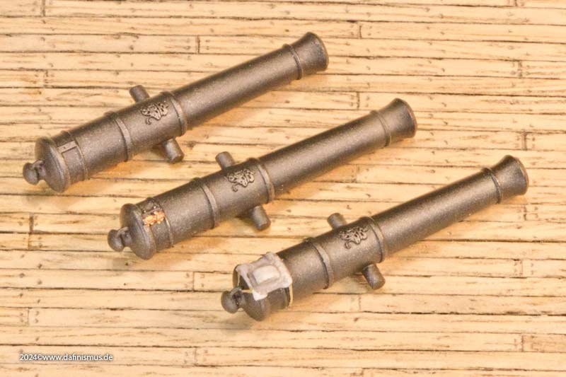
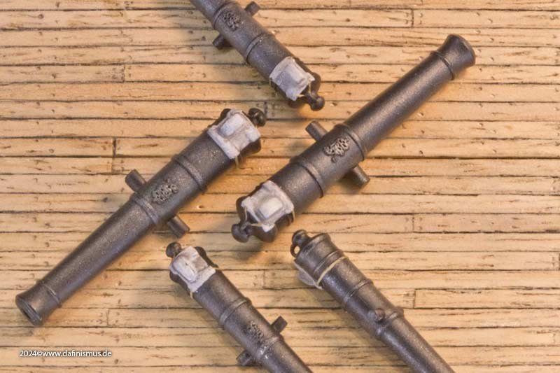
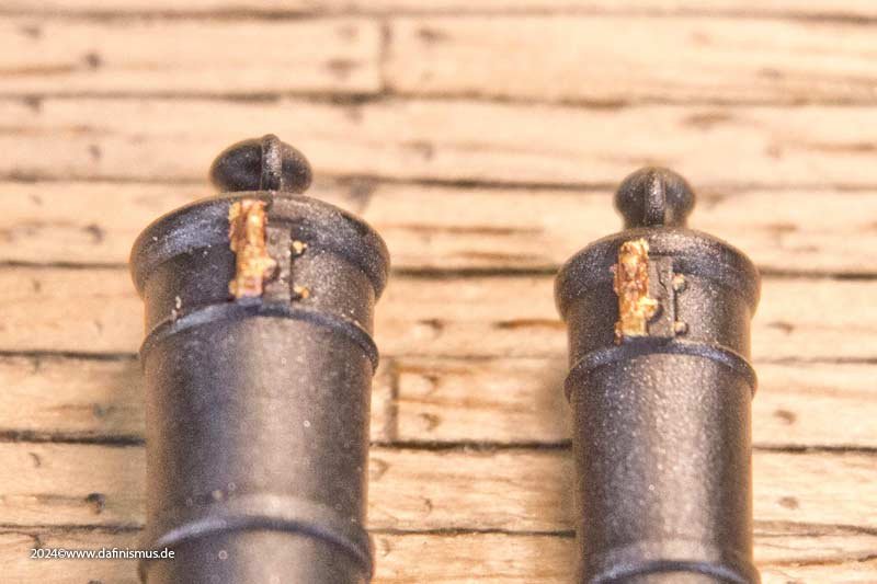
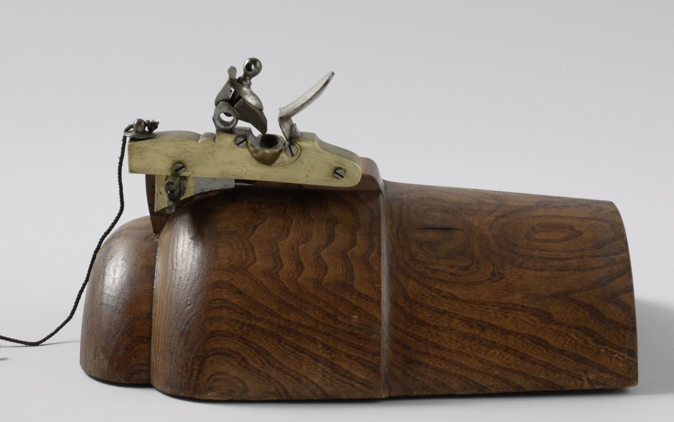
So one never stop learning, one never stop learning ... So, the gunlock has been moved to the correct position, and I hope it's now a little closer to the original 🙂 Flanged to the starboard side of the ignition pan of the barrel, the retaining bolt(s) pass horizontally through it, so the barrel itself does not need to be weakened. The pan of the lock protrudes above the pan of the barrel. There were also corresponding changes to the lead cover, with the cap moving slightly off-centre. Accordingly, there are again three variants of the representation, with cover, flintlock and open ignition pan. The flintlock shows that the printer is at its limit, and when the metallic paint is added, it looks a bit washed out in close-up. Here is the lock with just primer, which adheres better. And here is the dimensions-based visualisation. Have fun 🙂 XXXDAn


-
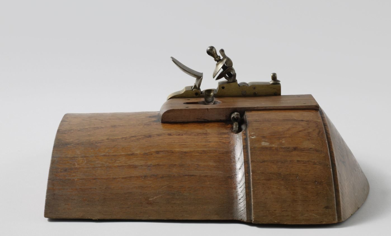
Thank you druxey for your kind corrections! All the pictures that I have from Victiry´s guns are that bad in quality, that I only was able to see it once I knew what to look for. Here are some better ones from the dutch Rijksmuseum showing the principle (Both pictures are not the same lock!) A TREATISE ON NAVAL GUNNERY by GENERAL SIR HOWARD DOUGLAS, Bart. FOURHT EDITION, REVISED, 1855 Page 397ff SECTION III - ON LOCKS AND TUBES FOR NAVAL ORDNANCE. 370. The general introduction of flint-locks into the British naval service resulted from the efficient firing of the " Duke," of 98 guns, on a celebrated occasion, that ship having been previously fully equipped with gun-locks by her captain, the late Sir Charles Douglas, who commanded her from April, 1778, till November, 1781, when he was removed into the " Formidable," as Captain of the Fleet, in which ship he likewise intro duced these and other improvements in naval artillery. The equipment of the "Duke" with flint-locks to all her guns was effected in a manner so characteristic of the ardour and energy of that enlightened and scientific officer, that the author trusts he may be excused for adverting to it in a brief statement of facts, which will, perhaps, be deemed somewhat interesting by the pro fessional reader. On Sir Charles Douglas's appointment to the " Duke," he brought before the Admiralty and the Ordnance several propositions for improving, facilitating, and quickening the service of naval ordnance. The car tridges were at that time all made of paper, which required the operation of worming guns after every discharge, on account of the lower end of a papercartridge remaining generally at the bottom of the bore in a state of ignition. To obviate this, Sir Charles Douglas proposed that the cartridges should be made of flannel. He recommended, and urged repeatedly, the full equipment of his ship with flint-locks, by which the use of the slow-match and the powder-horn for priming might more or less be discontinued ; and as tin tubes would manifestly be dangerous and highly objectionable on the fighting decks of a ship, he recom mended that quill-tubes should be substituted for them. 371. Neither of these propositions was immediately or fully adopted ; paper-cartridges, the match, and the priming-horn continued for some years in general use. It appears by official documents * that no locks were supplied during 1778 to the " Duke" at Plymouth, where she was commissioned in April of that year ; but in the following year she was furnished, at Portsmouth, with two locks for 24-pounders, four locks for 12-pounders, and two for 6-pounders ; total eight locks. Yet the " Duke " was fully equipped with gun-locks in the celebrated victory of the 12th of April, 1782, to which that ship and the other three-deckers, the " Formidable " and the " Namur," so greatly contributed. By what means then had the " Duke," in the previous years, been completed with these important implements ? By Sir Charles Douglas, out of his own funds and by his own energies : he bought a sufficient number of common musket-locks, which being let into pieces of wood, as into the stock of a musket, might then be fastened with iron wire to the guns." He purchased flannels sufficient to make bottoms for paper-cartridges, goose-quills for tubes, and the ingredients necessary to fill and prime them. On Sir Charles Douglas's appointment to be Captain of the Fleet he was succeeded in the command of the " Duke" by Captain, afterwards Lord Gardner ; and, in the battle of the ensuing year, the quick and efficient firing of that ship was so conspicuous and powerful as to enable the gallant Gardner to widen the gap which his leaders had made in the enemy's line, and so open the way for Rodney to pass to a memorable victory. That glorious day settled the question of the locks, by bearing down all further opposition to the introduction of improvements which the prejudices of the time deemed useless and unnecessary refinements ;* but that battle having likewise put an end to the maritime part of the war, no measures for the supply of locks to naval ordnance appear to have been taken till 1790, when " brass locks'" of a new pattern were provided, and continued in general use throughout the late war. These no doubt contributed greatly to the efficiency of our practice, to the accuracy and rapidity of which all French authors attribute the superiority of our gunnery in the actions and battles of the early part of the war, the French not having adopted locks till 1800. 372. The flint-locks of the pattern of 1790 remained in general use till 1818, when the double-flinted lock, likewise adopted by the French, of the author's invention, a drawing of which was given in the former editions of this work, was ordered for general use in the navy. [...]
-
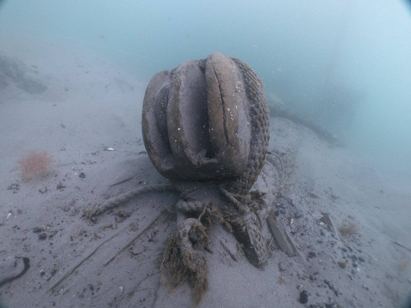
Thank you very much druxey. I took the orientation from the picts of Victory´s guns, but without this hint the side shift wasn´t to realise for me. Too much black barrel around 😉 No problem to move to the side. The advantage of printing. So the artefact of the cover in Thorsminde also could be complet? I always guessed that one side broke off. But seen the assymetrical position it could be still intact? XXXDAn


-
Thank you druxey! Looks to be worth a visit 🙂 Here some more links: https://bucklershard.co.uk/ https://bucklershard.co.uk/shipyard-trust-launches/ https://bucklershard.co.uk/attractions/bucklers-hard-museum/ https://bhshipyardtrust.org.uk/ (under construction)