HOLIDAY DONATION DRIVE - SUPPORT MSW - DO YOUR PART TO KEEP THIS GREAT FORUM GOING! (89 donations so far out of 49,000 members - C'mon guys!)
×


dafi
-
Posts
2,426 -
Joined
-
Last visited
Content Type
Profiles
Forums
Gallery
Events
Everything posted by dafi
-
 As this feature is also shown in drawings of the Victory as mentioned above, I had a closer look at the possible purposes. There are many ropes on the mizzen mast but little space. In case of "overpopulation the lines could possibly be handled fom the quarterdeck, as I know from personal experience that the gaff peak and fall need larger crews to get hoisted, leaving little space on the poop for all the other lines and duties. Just a thought but logical to me. The fair lead would keep the rope in place and avoids scarfing an the edge of the higher deck. To be operated properly this would possibly also needs a pulley on the lower sitting deck to get the rope in a suitable workable height. XXXDAn
 -
Thank you for the feedback druxey, very appreciated! The futtock staves will only be trimmed once all the shrouds are in place and fixed, in case I need to reposition them for any reason. And for the spelling, I first had futtock but when double checking my translation in Marquardt german edition*** his translation for the term was with a "b" in the start to my great surprise. So I just found a spelling mistake in this classic 🙂 XXXDAn ***PS: And it is a book dear to me, as the copy I use has a personal dedication from him to me, as I helped him with his original homepage back then 🙂 https://karl-heinz-marquardt.com/ PPS: I corrected the wrong spelling. A buttock stave is actually an expression existing in german regarding a stiff person, one says he/she has a b...
-
Here you can clearly see the difference between the wooden dead eyes from the early stages of my model and the new printed ones at the top of the shroud. With the wooden dead eyes, I had to close the unsymmetrical holes and re-drill them. It was a lot of work. In addition, the lower dead eyes have an incorrect all-round groove: As with the upper dead eyes, this is wide to accommodate the heavy shroud. For the lower dead eyes, however, the groove should be significantly narrower, i.e. only a slot, which only had to accommodate the thinner iron fitting. The appearance is also more even. In addition, the groove is not circumferential, but interrupted in the area of the connection to the iron or shroud. This also prevents the juffer from rotating. And even a careless model builder like me gets a subtle hint from the resulting bulge in the shroud if he is about to bind the dead eye the wrong way round ... In the picture you can see the comparison of the lower dead eye on the left with the narrow groove and on the right the upper one with the wide groove. XXXDAn
-
The next step was dead on onto the dead eyes 🙂 Before I started, I lifted the fighting top and checked that all the shrouds were in the right order. And indeed, there were two pairs on the starboard side in the area of the landlubbers hole that were lying crosswise. Then the shrouds below were assigned to their dead eyes. God bless the inventor of the hair clips! There is almost nothing better for pre-tightening some rigging than wooden clothespins in combination with gravity. Then came a rough binding on both ship´s sides to get an even pull on both directions. As I had reinforced the mast well with a wooden rod at the time, there was no movement in any direction. It still looks wild, but it does the job. To stabilize the rigging further further, I inserted the futtock stave. This stave is served over its entire length, in the original its a rope slightly thinner than the shroud, for the modeI I chose a core of 0.5 mm brass wire for stability reasons. The official calculation is slightly different, but by analogy the following measure gives the same figures: Distance upper edge of cross tree to lower edge of mast cap ... ... is the same as the upper edge of the cross tree to the futtock stave. Once the futtock stave was in place the "white glue serving" was also brought to the correct length. Afterwards, I will continue the serving evenly below the sausage by a few millimetres and also use black paint to ensure a uniform appearance. At the moment only the outer shrouds are attached so that the other shrouds can still work. Nevertheless, this already stiffens the whole construction. This also allowed me to start tidying up the dead eyes. Four seizings for the dead eye in the shroud, and crossing of the lanyard on the back of the dead eye and tied to the side after a few windings. And then it's on to the happy dead eye tying http://www.shipmodels.info/mws_forum/images/smilies/icon_smile.gif XXXDAn
-
Then came a new adventure, the shrouds. Somehow, all the interesting things I wanted to try always came to the point where the shrouds would have been installed. So I couldn't avoid it any longer, so I set off on a new adventure. I ordered the cables for the shrouds and stays from www.modellbau-takelgarn.de. They had the complete range in tenths of a millimeter increments, and the standing rigging is a deep brown and not the usual bluish deep black. The brown allowed me to achieve the color I wanted. First I made the ropes a whole lot darker with heavily diluted black artist's ink. What a mess that was. The lawn in the garden still looks sunburnt, but the new appearance is now a deep deep brown compared to the original. ... To dress the eyes around the masthead and the first shroud, I went back to the glue fake method that I had already used for the bopstays. To do this, I measured the area to be dressed and always made a marker knot at the borders with a makeshift yarn as a glue border. Then I applied the fake dressing. This involved the eyes below the crosstrees on a length corresponding to the masthead´s height and the foremost shroud along the entire length. The procedure was always the same: apply a generous layer of white glue with a small wooden stick then spread the glue well with your fingers using the three-finger method and smooth with spit, allow to dry, then repeat and finally seal with black paint. The shrouds were now ready for further assembly. Next, I determined the circumference of the masthead ... ... and made a template. A 10 mm round stick was wrapped with paper until the required 11 mm of the test loop was obtained. The loop of the shroud was fixed with a pair of clamping tweezers ... ... tied with 10 knots - 5 at the top and alternating 5 at the bottom ... ... and the package neatly secured with a seizing. The two pendants were given their thimbles. As there is an odd number of shrouds, the rearmost one was joined to the opposite side in a horseshoe splice. And then there was the first trial assembly. Pendant starboard, pendant port, first pair of shrouds sb, first pair of shrouds bb and so on. This allowed me to check whether the aft shrouds would fit under the aft cross tree - they didn't at first. So I raised the pairs of shrouds again and successively turned all the pairs further forward. And then it did fit. When the stays came to lie on top, everything was tightened up even more and now keeps the rear cross tree well clear. XXXDAn PS: Here you can see again how model builder's impatience would take revenge if you had already glued the mast cap or even the fighting top ...
-
My understanding always was that the capstans were used using the top rope scuttles to lead the ropes via a blocks on the capstan´s level deck to hoist the boats. But seeing the drawings, the complexity of coordinating the 4 ropes and the attached calculations of resulting weights, the conclusion of no capstan but enough men being used is the far more attractive to me 🙂 XXXDAn
- 27 replies
-
- 2
-

-
- capstan
- small boats
- (and 1 more)
-
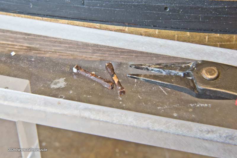
Thank you Patrick! Next I noticed that the boarding spikes were still missing. There are two rings to be doubled on my etched parts set, so I stapled the through-holes together using 3 suitable wires. And even this corner improved as a result. XXXDAn
-
After objection to the visible separation of the bitts at deck level, what I do best was done, demolition ... ... on the right the old two-part bitts and on the left the new one-part bitt http://www.shipmodels.info/mws_forum/images/smilies/icon_smile.gif The next step was the planking of the deck. To do this, I built a first template ... ... only to realize that this shape impairs the view too much and shadows everything below. So V2 with the first few meters of the gangway. After that, I first had to extend the substructure. The first impressions of the deck during planking are always a bit gruesome ... ... but after sanding it fits. As always, I put some cotton pads in to clean up the edge of the waist. And being very high-spirited, I decided to use another original kit part. But the holes for the eyebolts were too big, so they were sealed with 1 mm Evergreen round material and re-drilled with 0.5 mm. A few more etched ring bolts from my set resulted in a nice new corner on the ship. XXXDAn
-
Main mast area, summer 2024: Some new deck pillars have found their way onto the ship, increasing the number of original kit parts used immensely but because of this, some of the incorrectly placed ones had to make way for others. Some coamings were also newly created ... ... and then the internal structures around the main mast were added. XXXDAn
-
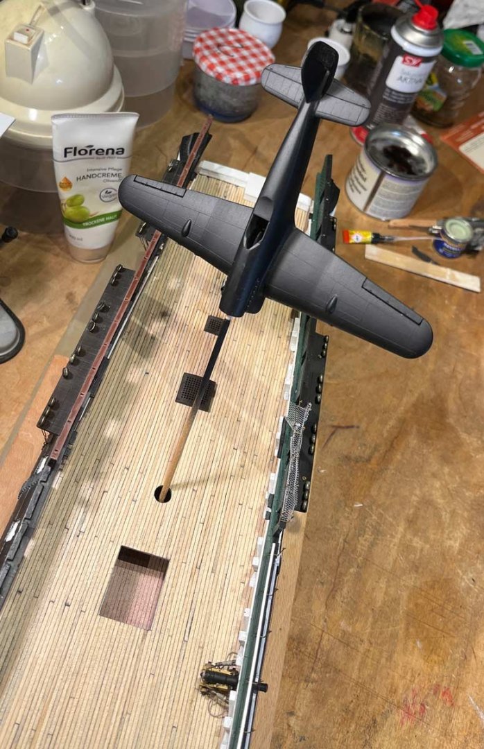
Something strange happened on the way to the shipyard ... ... no, it´s neither England 1940 HMS Wellesley against Luftwaffe nor Okinawa 1945 USS Bunker Hill and japanese kamikaze ... ... XXXDAn https://www.google.de/search?q=hms+wellesley&biw=2319&bih=1379&tbo=u&source=univ&sa=X&sqi=2&ved=0ahUKEwiPhd6J09PJAhXKXRQKHcDMBdAQsAQINg&udm=2 [URL=https://en.wikipedia.org/wiki/HMS_Wellesley_(1815)]HMS Wellesley Wikipedia uk[/URL]
- 58 replies
-
- 3
-
-

-
- Revell
- Constitution
- (and 1 more)
-
Anyway you need different sizes for the different yards 🙂 I took 1.8 mm diameter for the top yards and 1.4 mm for the topgallant, a good balance in between appearence and handling. Do not forget the ribs in between 🙂 For the gaff and boom I use 1,5 diameter with the same length but no rips. And here some parrels in their natural habitat on the topgalland yard of Hendrika Barthelds. Much smaller as the sail is smaller too, no ribs and one can see, some loosness and space on the rope, as some of the balls have exploded in a recend storm. The able seaman (not me landlubber) was replacing them shortely after this picture was taken 🙂 XXXDAn
-
If the knots are getting too big, that it a good sign that the yarn for the ratline is oversized! Circumference 1,5 Inch on the lower masts on big ships, otherwise just 1 inch. Just calculate the diameter for your scale 🙂 And with some training, the clove hitch goes as fast as an overhand knot but looks far better in an even appearence. XXXDAn
-
I think the warm water is a better option than the hair dryer, as it is better controlable. As most paints are not touchy against water, it should not matter. If it is, just wash off all paint in the process 🙂 Still replacing is one of the best options 😉 XXXDAn
-
Have alook at paintings of the said period and nation. Best clue you can get. XXXDAn
-
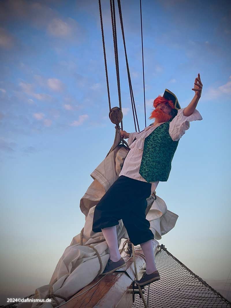
It was marvellous, especially as, unlike modern yachts, the old lady really is sailed as it was done some 400 years ago, so we had 1 skipper, 2 able seamen and us 25 landlubber who had to lend all hands as instructed. Almost everyone is needed to set the gaff sails. Hoisting in and stowing the headsails is also a marvellous task, especially the outer jib with the largest sail mass of the three sails and the smallest space to work on, as the net actually leaves no room for feet. And the mass of cloth can really put up good fights, especially with some wind incorporated. And knowing that, unlike the sailors on the Victory 250 years ago with their much larger sails to cope with, we were are at least well secured out there ... In the past, it was the sailors who built models, today the modellers come to the ship FCC to understand what they are actually building. And there are few places one can get closer to this than folding an outer jib 🙂 XXXDAn
-
Happiness is a warm gun ... ... nooooo ... Happiness is once again being able to stick your nose in the wind ... ... with space above it ... ...and space below. Just let your gaze wander to the horizon. It's funny how everything suddenly looks so small. And let the little blue spot - aka Sweetheart - drop a little kiss from above. Or wave to the boys in the jib net ... ... or take a leisurely stroll at the front of the jib boom and enjoy the wind, sun and waves at over 8 knots. And look forward to the evening, because the 3 headsails ... ... I was allowed to salvage and stow it every evening while still underway, so that everything looked safe and smart in the harbour. And this is the old Lady, the Hendrika Bartelds ... ... just to be happy XXXDAn

-
But of course I did! There was no other way getting me the rum - they found out I can´t sing AND drink at the same time ... XXXDAn
-
Strengthening the mast, but at all times not only war, means also in bad weather 🙂 XXXDAn
-
The best parties always take place in the kitchen. First of all, of course, we need the kitchen worktop. Coincidentally, one of the prints I had made for the Revell Constitition fits like a glove, no wonder, almost the same scale and the design was based anyway on the design of the British 😉 Anyway, the kitchen and hearth are only worth as much as the life that takes place there. The first three men assigned to kitchen duty were quickly pressed. Frederick Bush, the 24-year-old, hunky German is fetching firewood, Irishman Thomas Foley, at 47 one of the oldest crew members on board, will be working on a meat-like structure and Hans Yaul from Switzerland will be chasing the protein-rich maggots out of the cheese with his big knife. Number 4 was more of a challenge. It's always nice when the kits come with little men, but they're usually not the right kind of hands-on character. Here on the right is a sailor from the Constitution kit. Any sailor would immediately fall over on land with his legs in a row like this, so I first changed the leg position to a stable three-point position and also tilted the head slightly for the dynamics. After all, he should be fuelling the stove. However, the test position then showed a completely incorrect and far too static posture for this. So he bent his back and brought his second arm into a working position. Now he finally looks like somebody doing a job. Number 4 is alive 🙂 I then used one of my misprints to prepare the wood filling. The grill at the front of the Brodie Stove has 3 sections, so apparently you can fire it in 3 sections depending on what capacity you need. This is also the log length that dear Frederick has in his arms at the moment. Afterwards, the lower decks are secured against falling objects with cotton wool pads ... ... and the grill is carfully loaded with firewood. We now know that our dear Lord of the Fire is 28-year-old James Caton from Brazil, with the logs that Frederik has placed in front of him and two bags of coals next to him for a nice, even heat. And here you can already see why I had to shorten the height of the Brodie Stove compared to the original drawings: of course it has to pass under the deck beam and the two lids at the top should still be accessible. That's why there is a gap of exactly one deck beam width between the chimney and the lids at the top. How these two boilers could be effectively operated and cleaned with this limited access is still beyond my understanding. Just like the automatic turning mechanism of the grill spit at the front. I know of English country houses that have a similar system, but there are usually much larger fires at work. The mechanics of the drive chain and the corresponding bearing of the spit are also not yet technically comprehensible to me in detail, even if they are based on identical plans in the NMM. Furthermore, you have to bear in mind that the whole stove in Portsmouth is only a replica based on the plan just mentioned. I think back then, the stove size and installation situation were customised for each ship. Whether this is all correct in the replica is therefore not known. And fortunately, the difference in height is no longer noticeable once installed in the model. And while we're on the subject of size and deck height, Frederick, with his height of 1.9 metres, which was unusual for the time but not uncommon, also has a problem here ... ... that standing is just about possible, but the next deck beam is already lurking for his head. So he was clever enough to adopt a slightly more stooped posture to wriggle himself past the firewood, the coal bags and the water barrels. In the small cooking chamber you can already see that with two people it's going to be a tight squeeze, especially if there's someone else working on the stove. I have deliberately avoided decorating the worktop like the breakfast buffet in Portsmouth, as everyone brings what they need for cooking from their mess and has to leave a clean worktop afterwards. After all, this is the only cooking area for 800+ crew members. And that's the end of the small picture in the picture, just a few more impressions 🙂 Prost Mahlzeit, XXXDAn
-
Thank you druxey! Well, Augsburg is now over and all buyers of my block collection have received a free update that includes the Steel specifications. I hope I haven't forgotten anyone, if not please let me kno 🙂 And after all those blocks, time for a chang 🙂 A long time ago I had already presented the built Brodie stove. Cooking place for 800 men. First mishap - I had actually misplaced it for almost a year ... Second mishap - space test and the stove turned out to be 2 mm too high ... In the meantime, because of the unavailability of the original, I had made it again in print ... ... on the right the recovered stove, in the centre the first print - also too high - and on the left the right-scaled version, here the printing technique actually helped to quickly define the correct size, as I had scaled the stove in 2 % steps and could therefore simply place the results on my deck and select the appropriate size. And the winner is: XXXDAn
-
It was nice again and my little one with the black and yellow stripes really enjoyed the trip 🙂 As every 2 years there was a big meeting in Augsburg, around 70 modellers, some with their partners, met, chatted with each other, had a nice evening together and many even had a great Sunday breakfast together. Here are a few pictures of my little one with her accessories. I was also able to take part in and witness a Guinness of World Record attempt: Matthias registered his ship in a bottle as the largest free-hanging ship in a bottle. Now we're just waiting for the certification 🙂 Well then, a nice greeting from both of us, DAniel and Vicky