HOLIDAY DONATION DRIVE - SUPPORT MSW - DO YOUR PART TO KEEP THIS GREAT FORUM GOING! (89 donations so far out of 49,000 members - C'mon guys!)
×


dafi
-
Posts
2,426 -
Joined
-
Last visited
Content Type
Profiles
Forums
Gallery
Events
Everything posted by dafi
-
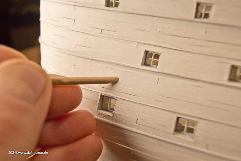
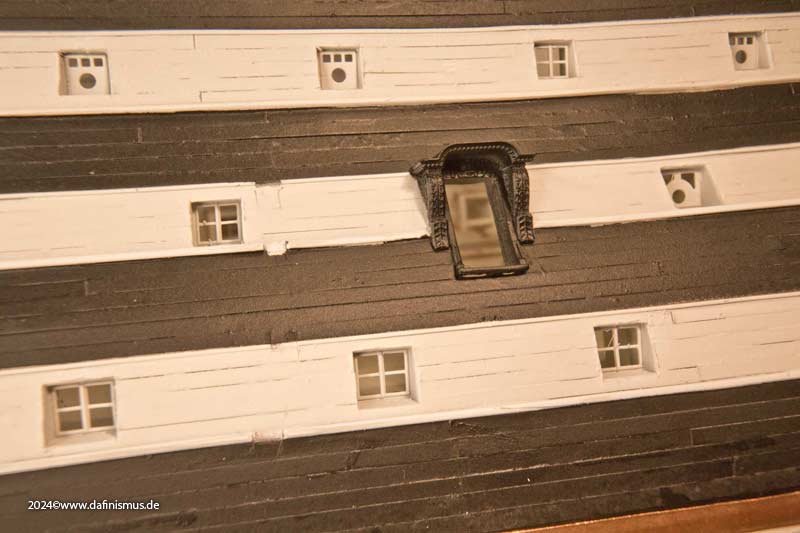
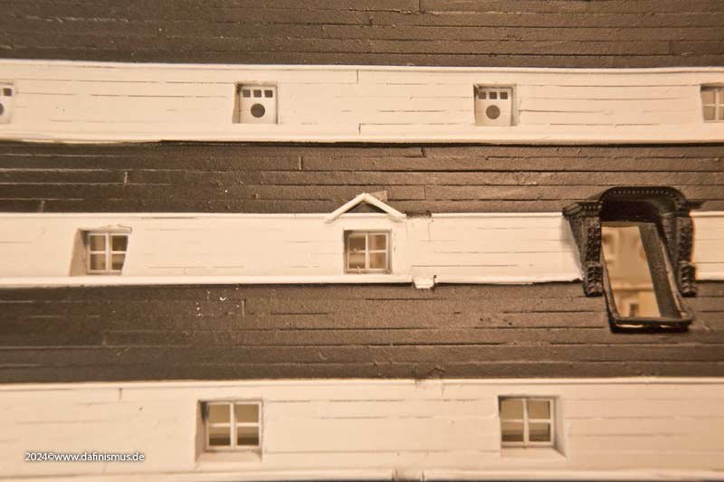
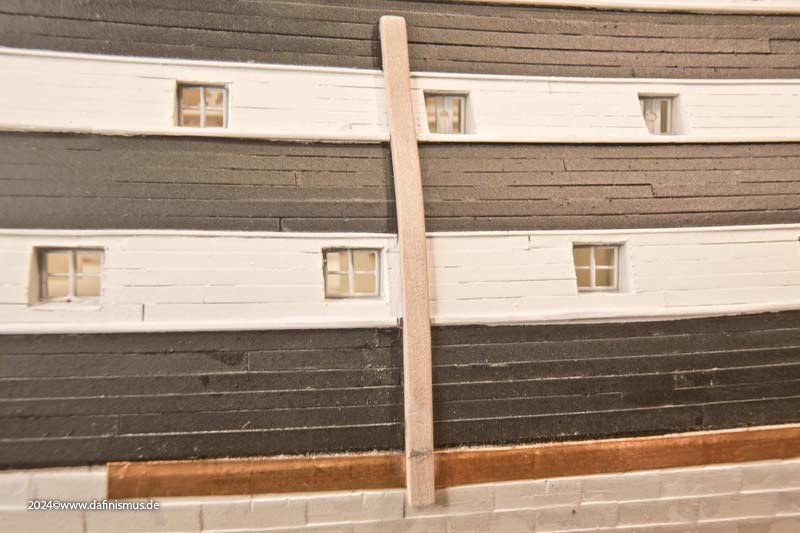
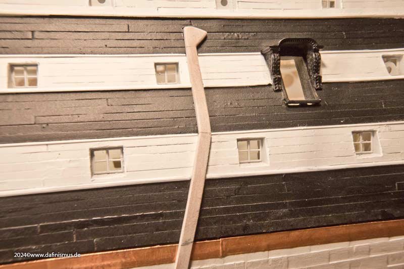
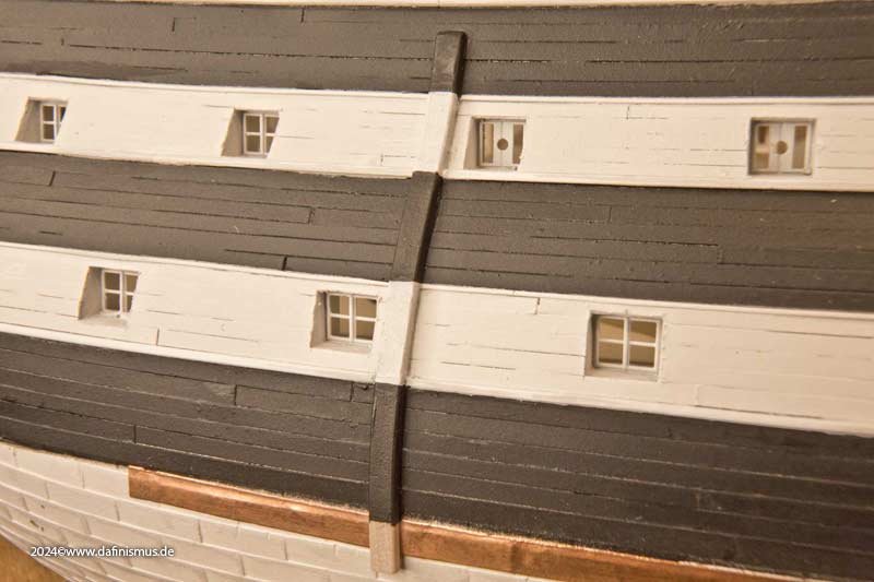
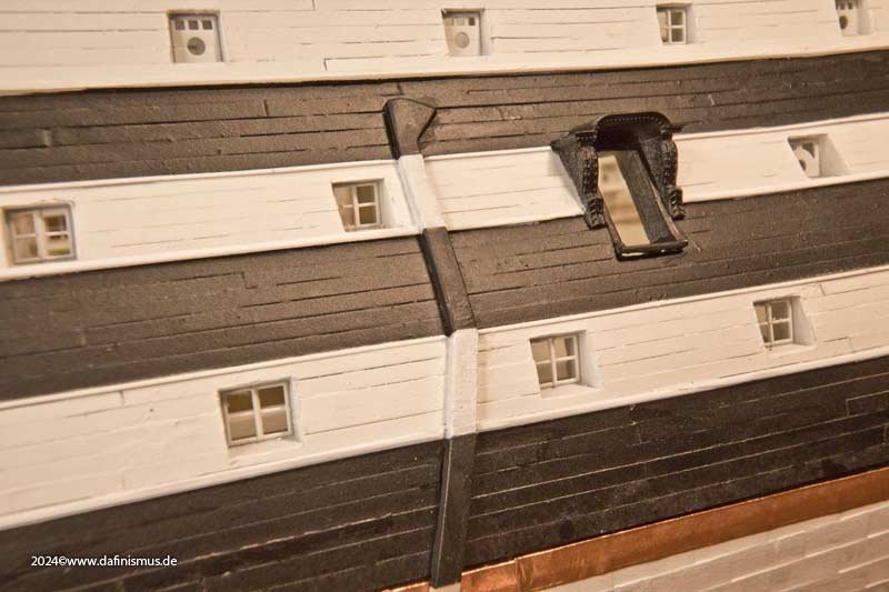
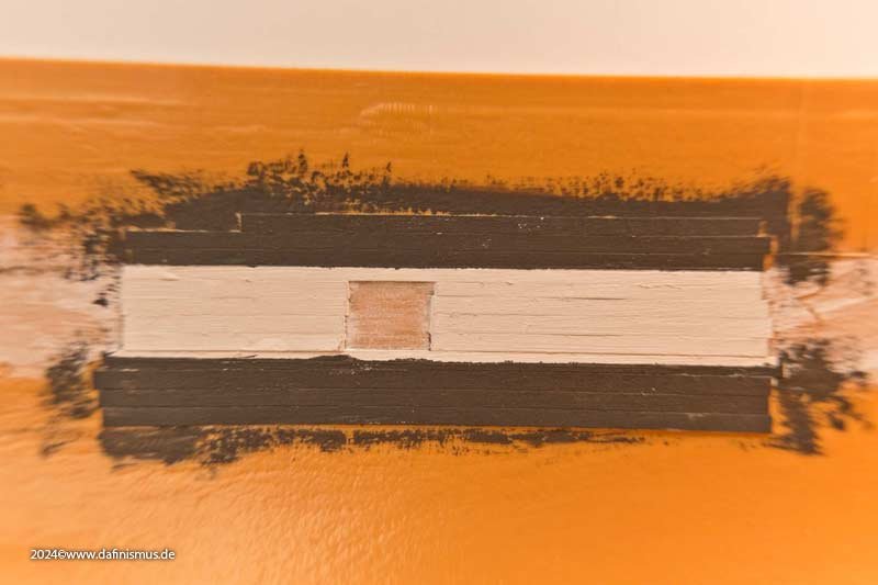
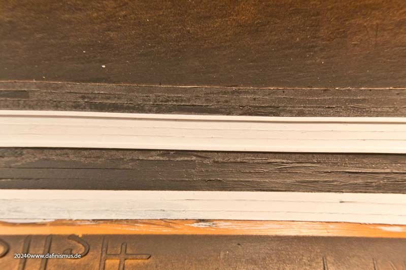
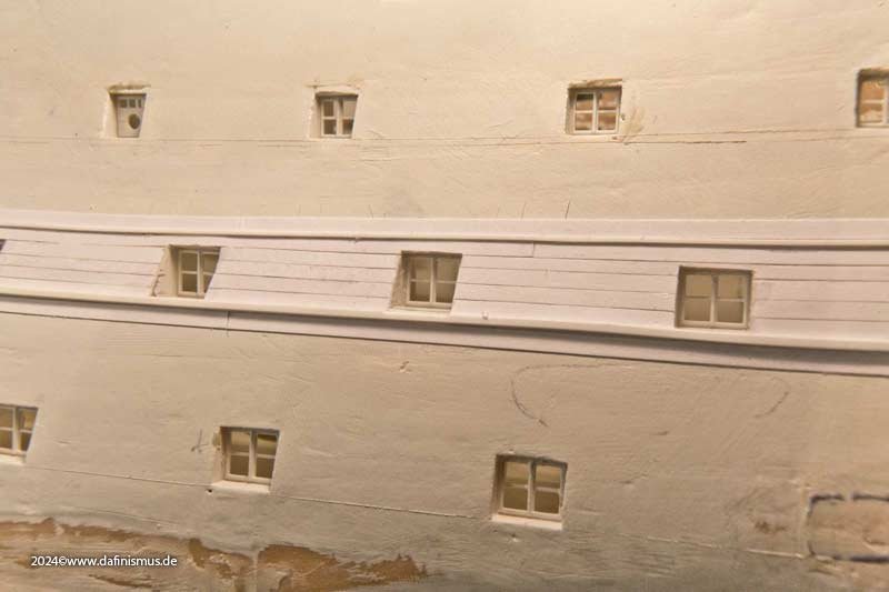
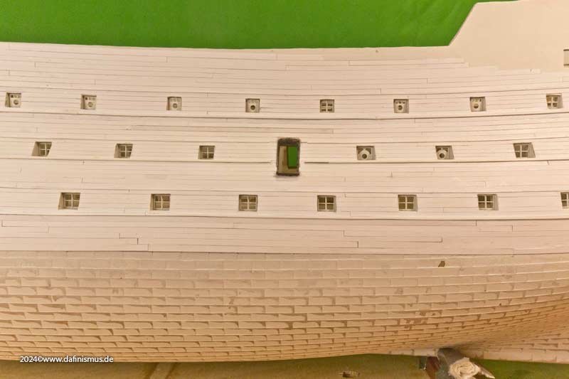
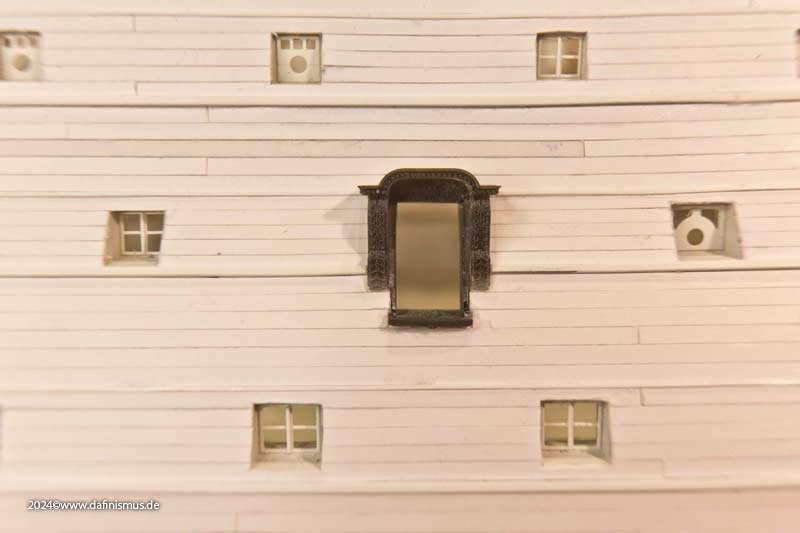
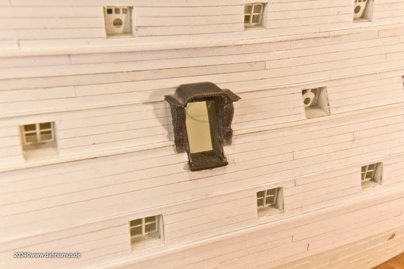
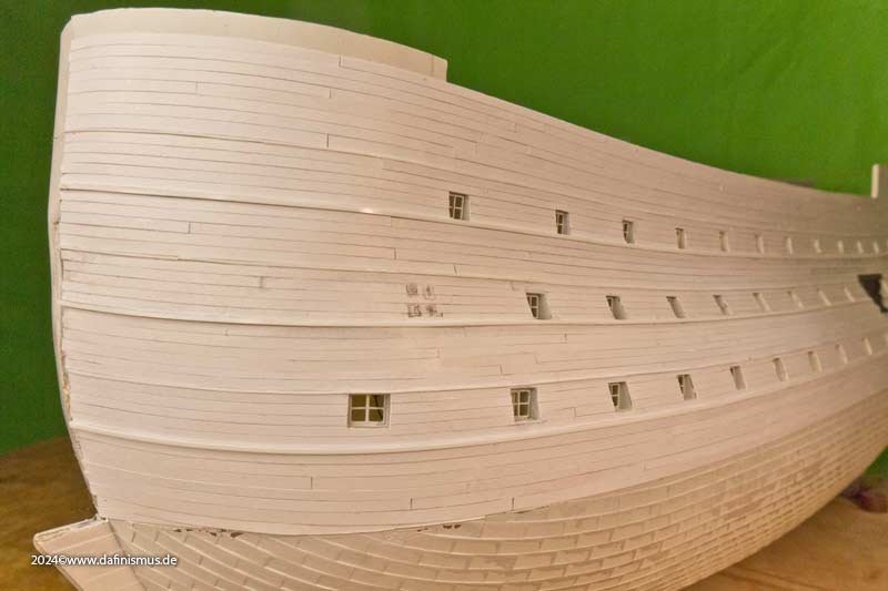
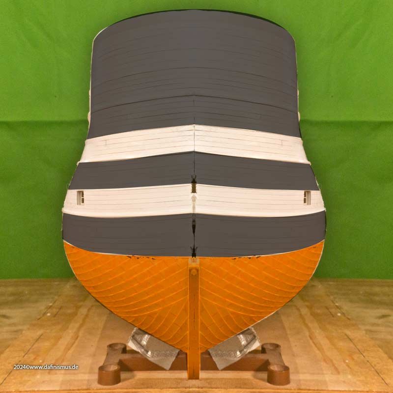
 When it rolls, it rolls, or the victory of impatience over model-building caution. Once I was this far along, I naturally wanted to see the whole thing in paint. This was a risk because the paper planking is quite sensitive and I still had to do the whole other side. But, but, but: it just had to be done. I had slightly oversized the separating battens, so I sanded the thicker one even thinner and broke the edges. It did the whole thing good. I used the masking tape to protect the paper planks. This worked really well. After the first round of white spray over everything, a beveled skewer was ideal for removing grains and impurities. Then I generously covered the white strip with masking tape and used the profile battens to cut it into shape with a scalpel, which went really quickly. Then black spray and removed the masking and simply: JOY! It worked. The first size sample of the rigols hung up. Very striking on the contemporary hull are the many additions, here the downpipes, probably plumbing. But with a little paint, they blend into the overall work of art in such a way that one thinks they have always been there ;-) Enjoy, DAniel
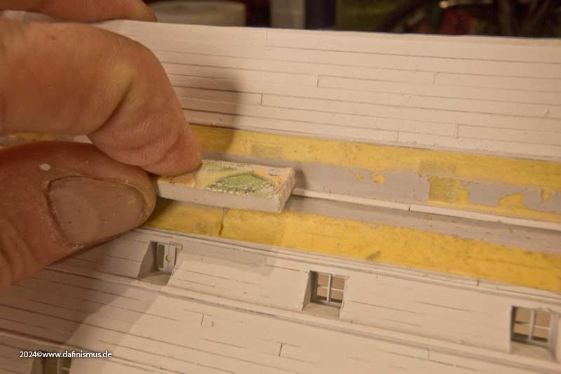
-
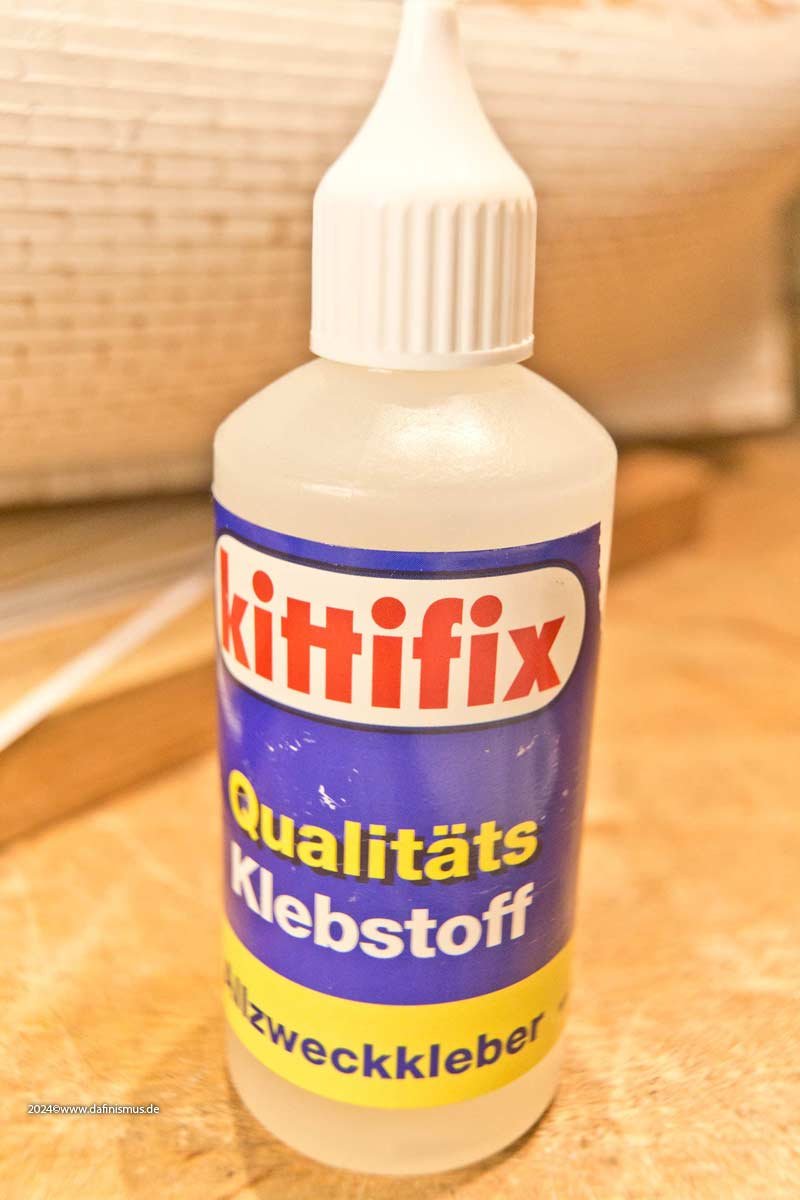
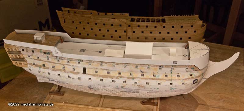
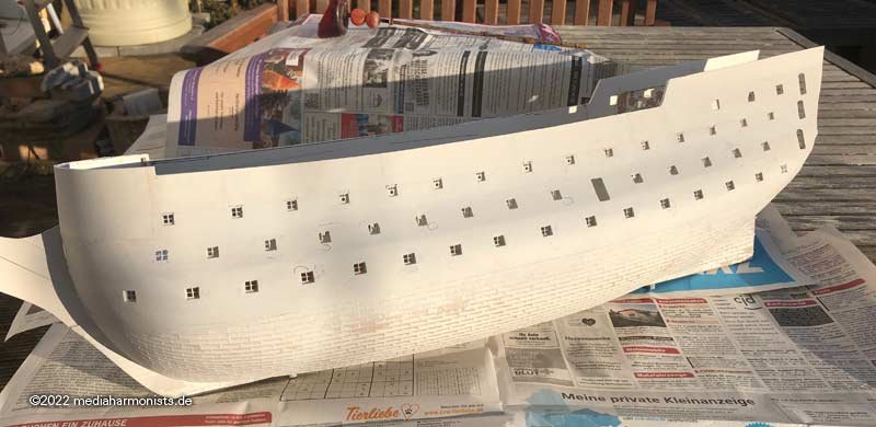
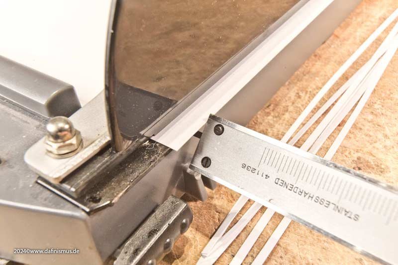
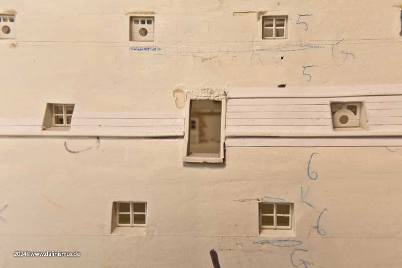
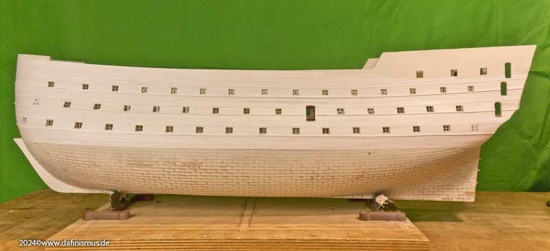
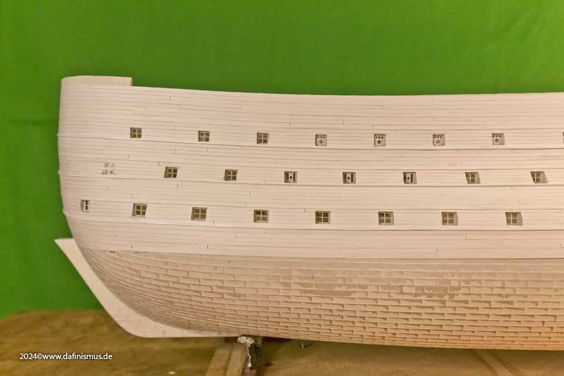
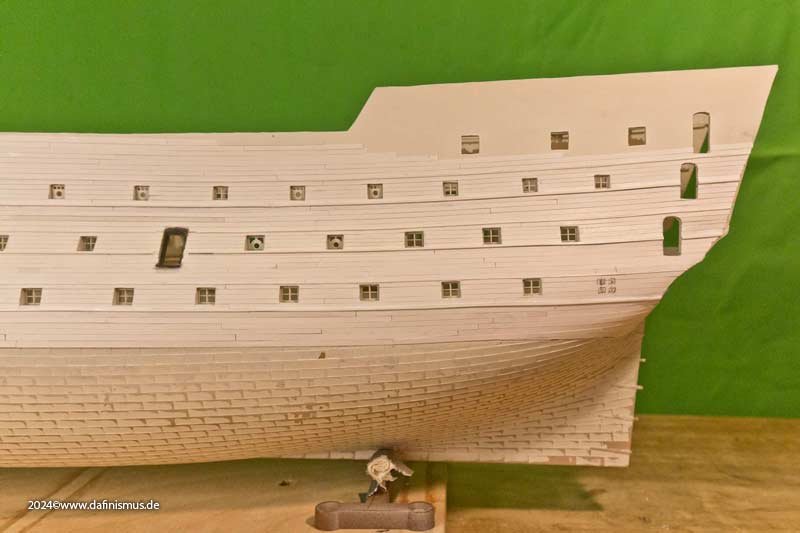
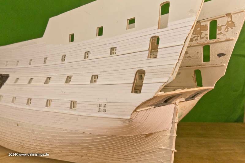
Well, and the little fat one with the stripes is still stuck in the camper van since Evian. Nevertheless, there is always enough Victory for me to do. I really missed the 1910 model at the last two exhibitions, as I like to show the developments on the ship. Time to take another look at my victorian black and white beauty. The first construction phase was January to March 2022, so that's already 2 years ago. A brief look back: After sanding down and fattening up the entire side of the ship to get a level surface, she looked all tattered at first. But the grace of the paint brought back some decency and dignity. But in this state I realized one thing: A lot of glue and car filler had caused the hull halves to warp outwards quite a bit, 2 mm on the port side and 6 mm on the starboard side :-0 Then I was initially frustrated, but also realized that I should let the material work out in peace and see if it would still turn out any good. And I think it's going to become something in the end. The good girl was released from her slumber and thoroughly checked. Deformation no had longer increased. However, it will take a lot of bending force, but I think the decks can manage this, with a little internal help if necessary. But that will only come when the time comes. Why? I can only insert the decks once the window panes have been inserted. I can only insert the window panes once the outside has been painted. And I can't paint the outside until the planks are in place. So I had to take care of the planks. In the past, I liked to use 0.2 mm ABS sheet, but the plastic glue tended to leave fingerprints. Wood was too thick for me and too time-consuming to procure. That's why I went exploring in my model maker friends' circles and found what I was looking for: 250 gram paper/cardboard. Initial tests were quite inspiring. In the original, there were wooden battens nailed on in two thicknesses to separate the colors. I made these from Evergreen, although I made them slightly thicker for handling reasons. So planks cut on the guillotine shears ... ... and opened the glue pot. First planks are slapped on ... ... and even that didn't put me off any further :-) And at some point the port half was planked, deliberately disregarding all planking schemes. And in case anyone thinks that the entrance gate visible today is original, no, the gate that can be seen today is from this state of construction and was installed in the ship between 1820 and 1828. One gate further back than as build. And these port parts were simply reinstalled one port further forward in 1920 and declared as Trafalgar state. Honi soit qui mal y pense. Fortunately, I've had the parts in my supply kit for a long time, so I just had to grab them. For me as a plastic person, the tight planking around the stern was of course something new. I'll have to clean it up a bit, then it'll fit. And I don't know why I remembered some well-known lines in the next picture ... "Beneath us, visible to all, lay a huge spaceship, one hundred and fifty meters long, shaped like a smooth sneaker, snow-white and maddeningly beautiful. At its heart was a small golden box containing the most sophisticated invention ever made, an invention that made this spaceship something unique in the history of the galaxy, an invention that gave the spaceship its name - 'Heart of Gold'." - The Hitchhiker's Guide to the Galaxy, Chapter 4 But what still looks like this ... ... should develop into this :-) Cheers, DAniel


-
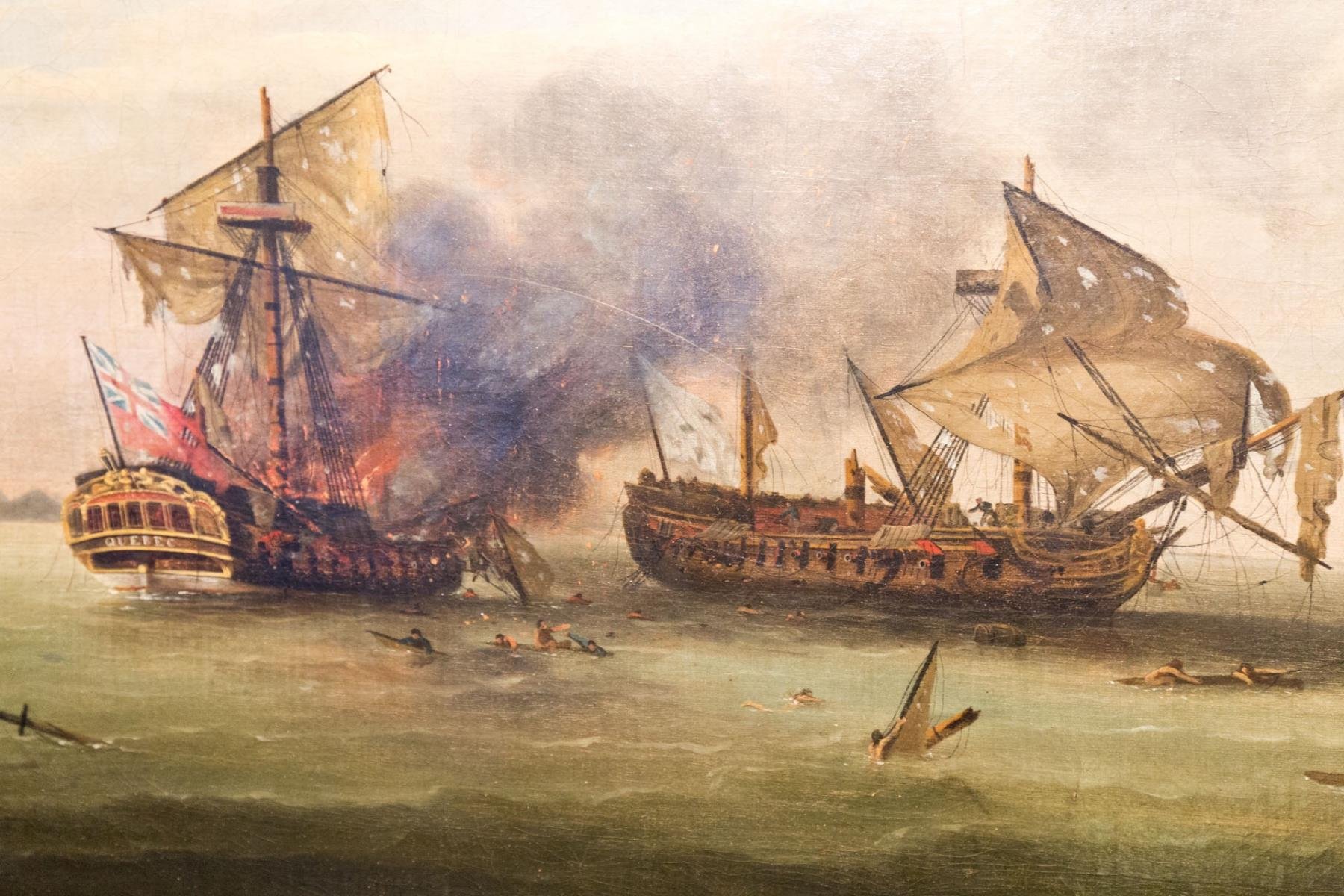
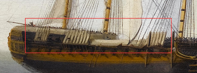
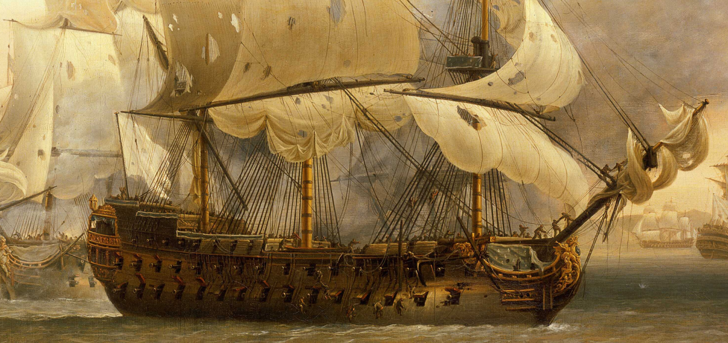
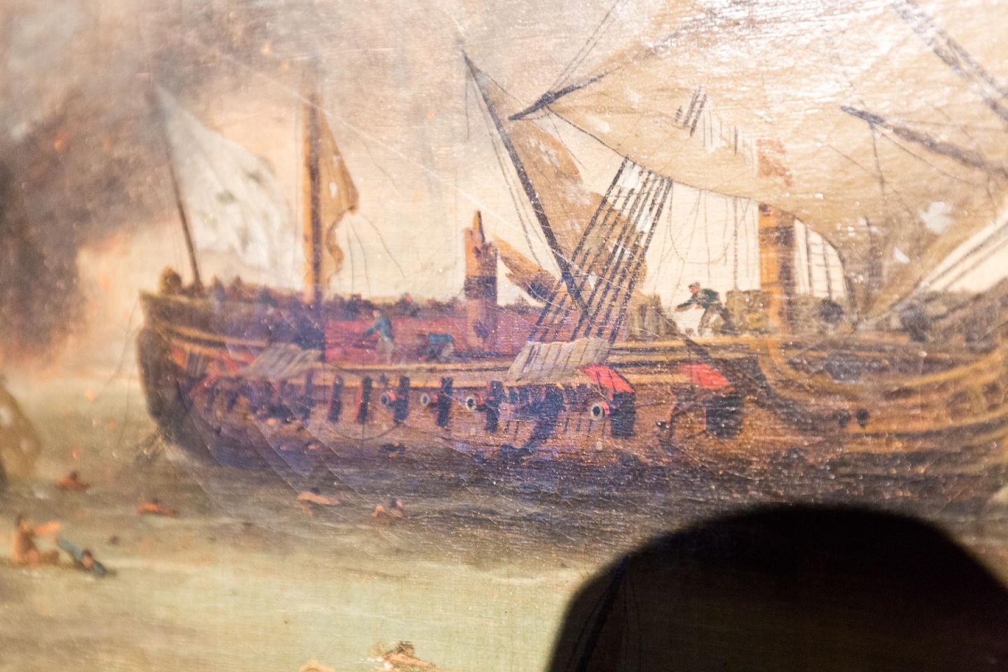
Hy all, I am quite sure that in the picture shown above those were simple cloth - or hammocks - but no hammock stanchions or solid builds for many reasons. First the picture from my Constitution fighting top in #4 is taken out of context, as this was a mere test shot for the proportions of the small howitzers placed up there during engagements. There is still missing the usually placed netting on the wooden rail, that served for safety reasons. The cloth on the rails are seen often and served for several reasons: Originally I know them as fighting cloth already from the times of the galleons and they served as view protecion for the crew while engagements on decks and atop. Often seen on Van der Velde. Those develloped very fast to be a colorful assets and in the 17 hundrets it was a most colorful decorative element to make ship look great as seen on many paintings. Also the same colored cloth was used for the handrails and bulkwards along the ship´s sides and in the tops. Sadely those elements were often taken out from historical models during restauration and I know of three that suffered that fate. Later appearing were those simple white cloth - sail cloth or hammocks - in case of engagement as view protection to hide the situation onboard or atop and the whereabouts of the fighting measures. Also on Trafalgar it was mentioned that wet white cloth was used covering the hammocks on Victory. I doubt that it was a permanent fixture especially in the tops as this would add unwanted surface for wind pressure and quite sure no fixed bulkwark for the same reasons plus the extra weight. The same goes for the hammock cranes. For the quote in #1 with the hammocks in the tops I give you another guess: In many pictures of engagements I saw the deadeyes and lanyards wrapped in cloth to protect them. So my guess is that the hammocks could have been used for that reason in the tops. 🙂 XXXDAn PS: Some fast found samples 🙂

-
In the meantime, the swivels have been finished. Here is the status of the last pictures ... ... the one with the breathing problem 😉 For a simpler assembly I have simply rethought. I already detached the trunnions from the barrel of the Constitution guns and printed them on the gun carriage. In this way I was able to represent the flaps at any elevation angle of the barrel and without the classic gap at the top. The tube then had the mount on the underside where the trunnions were: beautiful, practical and invisible 🙂 I used the same method here. The trunnions are integrated into the fork, stabalizing it while printing and especially during washing, and the mount was recessed under the tube. Now only 3 rounds of test prints were necessary until the necessary tolerance/clearance under the tube was found so that the mount works easily and yet with good guidance. Painting is done with the fork mounted, otherwise it will no longer fit. The test assembly was then possible without any losses within a few moments and, above all, in a very relaxed manner 🙂 And here's the whole little kit: the printling in its housing, which ensures that no small parts get stuck to the base plate during printing, as the superstructure "collects" them. It also serves as protection during washing and shipping. And on the left, the individual parts and the assembled piece. Visually, the assembled parts do not differ from the previous models, but they are much more precisely aligned and thus appear tidier. Incidentally, I borrowed the large fingers from a Greek Cyclops. They are slightly smaller than the North African ones. But only a little. Best regards, Daniel
- 58 replies
-
- 7
-

-

-
- Revell
- Constitution
- (and 1 more)
-
A while ago I was asked about the swivels in the Constitution's fighting tops. Since I liked the shown contemporary swivel, I programmed it, just to see what the printer would produce. The result was 3 separate parts: Barrel, fork and holder, the rear support of the fork is 0.2 mm thick. And you can see that it is actually fully movable, laterally and in height. Here the printing of the resin is no longer the threshold to the event horizon, but actually the pressure on the builder and his breathing to shear the 0.3 mm trunnions into the eyes of the fork. And with a little color, it looks pretty good. If only I hadn't shot off the front two ones, bluntly glued on is actually always crooked in this scale ... XXXDAn
- 58 replies
-
- 6
-
-
-
- Revell
- Constitution
- (and 1 more)
-
Merry Christmas everyone. It's been a while since Evian, but my little fat girl with the stripes is still slumbering in her transport box in the camper van. Too much to do in the time before the contemplative time. Nevertheless, there was some news. Late additions and news. First the late addition 🙂 Some time ago I needed some more guns. The proportions of the kit barrels are actually quite good, and with the etched parts you can also get the coat of arms on quite well. However, the most difficult part was always the part that you see the most - the muzzle. In the past, I had always closed it with some sprue and drilled a new hole, which was acceptable for individual pieces but annoying for mass production. Since I already had the basic programming for the guns of the USS Constitution, I took the Blomefield lines from the contemporary plans and updated them in the file and also added the coat of arms in the correct thickness for the scale. So I was able to reconstruct the whole set of guns quite quickly, I still use the gun mounts from the box. Here's the old and the new together. Here is the difference between the untreated kit carronade and the new one, once pure and once with paint. The long tubes also benefit. The basic proportions are correct, but now the reinforcement rings are more clearly defined and the crest fits the scale. Here is a comparison of the lengths of the 12-pounders: short, medium, long, medium, short. I also took the opportunity to attach the flint lock. Because you never actually saw the empty pan shown otherwise. Either there was a cover over it or the flint lock was fitted. I think it was worth it 🙂 XXXDAn
-
Carronades
dafi replied to DennisL's topic in Discussion for a Ship's Deck Furniture, Guns, boats and other Fittings
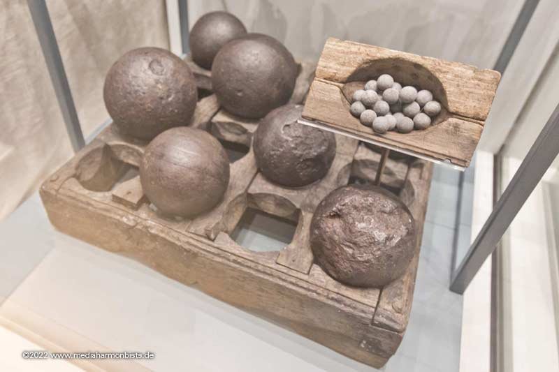
Also there were mobile racks for this purpose as the ones found in Thorsminde from 1811 XXXDAn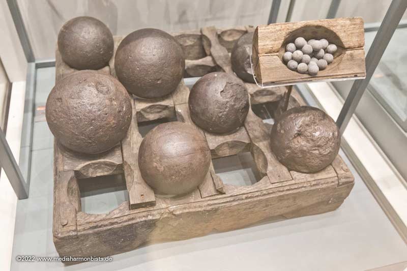
-
I saw some of these prints in Evian on the exhibition of the french arsenal group on the booth of Ancre and Mr. Berti. Those guns and other parts are very well done! What a great addition! XXXDAn
-
After many trials with real serving and other methotds even using wire I came for my Vic 1/100 to imitating the serving with white glue. Three layers of white glue, smoothed with spit and fingers, and then applying black paint. In my case the best result for the real thin ropes and also good in the time/effect ratio 🙂 XXXDAn
-
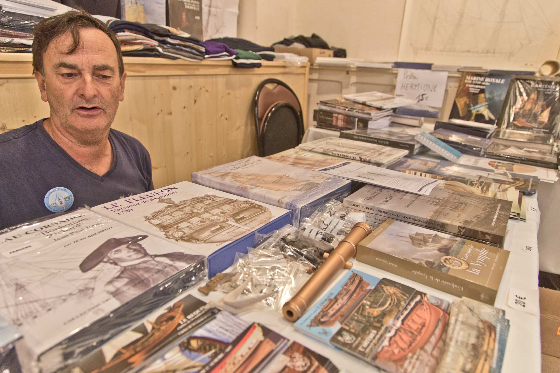
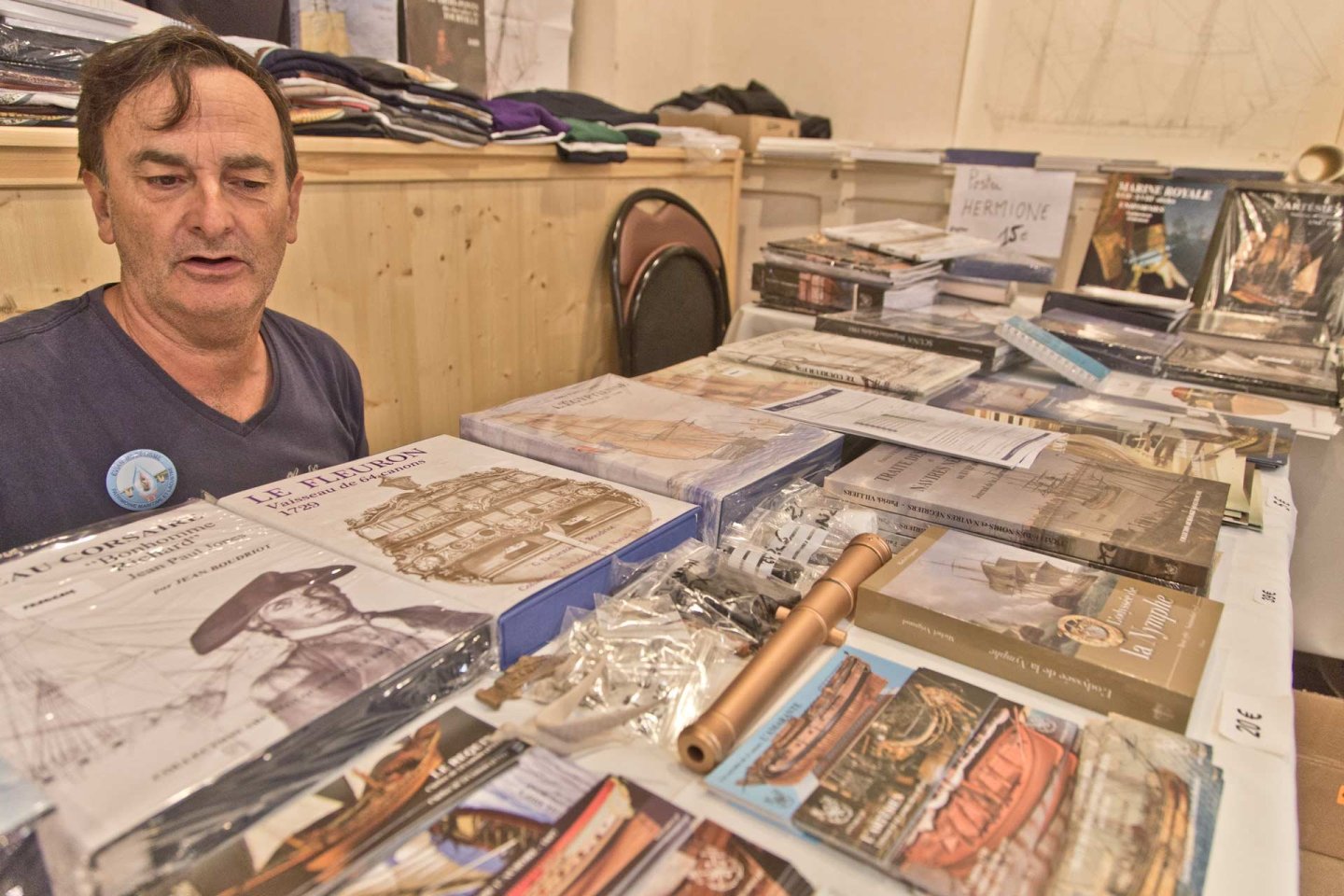
It was that time again. My little one had wanderlust again and wanted to get out. Evian on Lake Geneva was the destination this time, a big meeting of the French. And as Madame doesn't like travelling, I was allowed to come along too. And a few other bits and pieces. The SMS Trinkstein was a big hit! The number of times Joachim had to tell the story is mind boggling, as the dafi was never there, he was at all times everywhere and gossiping with everyone. Thanks Joachim for the help! Captain Hornblower's starting scene was also well received, Capitaine sans peur as he is called in French, the captain without fear. Various printed parts ... ... working stuff ... ... books ... ... and of course savoury slices - after all, the French are gourmets 🙂 And the little one was also very excited ... ...we had a photo session with her straight away. Best regards, DAniel
-
As I had some dicussions about this topic on the modelling conference in Evian, France, this weekend, I would like to bring this back to attention. Perhaps new prooves popped up? Cheers, Daniel
-
For the next level, I prepared the top mast shrouds. Even if Steel doesn't mention it explicitly, in most modern sources the foremost shroud is also dressed here, so that's what I decided to do. The sisterblock is also integrated between the two forward shrouds. But first come the hangers / burton tackles ... ... then the sister blocks ... ... and everything in place. Here you can see again the difference between the dressed and undressed shrouds. Unfortunately, in contrast to my self-made ropes, the purchased ropes do fluff a little, but this is not visible to the naked eye. To continue working, I tensioned the shrouds down with clamps and gravity. And dark ropes in front of a dark background are somewhat annoying even with good lighting, so I made a white cardboard template for this spot. Here you can see again the difference between the dressed and undressed shrouds. Unfortunately, in contrast to my self-made ropes, the purchased ropes do fluff a little, but this is not visible to the naked eye. To continue working, I tensioned the shrouds down again with clamps and gravity. And dark ropes in front of a dark background are a bit annoying even with good lighting, so I made a white cardboard template for this spot. Then the dead eyes were bound in as the lower ones. To compensate for the lack of a third hand, I then tied the shroud to be worked on with a thread to the yardarm, see green arrows, helps immensely. XXXDAn
-
After the fighting top had found its place, it was finally time to fit the futtock shrouds. The work preparation was the blackening of the etched parts and the painting of the dead eyes. Then the irons of the dead eyes were bent open, the dead eyes inserted and everything squeezed shut and secured with some glue. The upper hooks were then tied into the shrouds. This shroud was fully dressed, again using my technique with white glue as for my scale. First test of the dead eyes in the holes of the fighting top and the shrouds hooked in. Now you can see where the holes in the fighting top need to be reworked so that the irons don't sit at an angle. The lower shrouds have also been marked with a thread to hold the futtock shrouds. Next, the dressing of the lower shrouds was completed and brought to the same height. Finally the futtock shrouds could be hooked in, wrapped once around the futtock stave and tied to the shroud. After trimming, this is what came out http://www.shipmodels.info/mws_forum/images/smilies/icon_smile.gif XXXDAn
-
Next, I took care of the cleats for the hangers of the jeer blocks. In Portsmouth they are in the form of a bracket. All other literature that does not base on the restored ship show a shoulder piece. So the brackets from my printed parts go into the bin. Its up to the shoulder I took the opportunity to determine the length of the hangers, as I don't know how they will be accessible later. But more on the jeers later. And then it's finally its turn, the top mast. Placed in front of the mast, it is threaded through the trestle trees of the fighting top and pulled upwards using 2 pulleys in the foot. Here are some older pictures. The top gallant mast was also raised in this way, it is basically a very simple telescopic lift. XXXDAn
-
And the next stage was already on the agenda, I had just glued the fightig top onto the trestle trees when I remembered all the blocks that were needed underneath ... ... so I quickly tore the fightig top off and removed the glue residue. Well, that's the way it always goes with me. At least 4 small single blocks for the leech line and two double blocks for the buntlines have to go under there. But as I can't say for sure that that's all there is - as always, there are very many different sources - I have also fitted the other suspension points with blocks. But cutting them off is always easier than retrofitting them once all other things are installed. Based on the tests I had already presented some time ago, the first block still took just as long as the other eleven. But I had to develop a good strategy for them. First, I pressed the block onto a needle as usual and stropped it in. I secured the strop well with glue and only cut off the short end of the strop, but not the seizing ends. Then tie the remaining long leg with the seizing as a loop. The seizing has a double knot, but is not glued so that the loop can move. A thin thread with slip-through protection is passed through the hole from above ... ... and threads the loop of the block on the underside and ... ... pulls the loop onto the top and secure it temporarily with a wire hook. Then pull the long leg on the underside to bring the block to the correct length. Then carefully pull out the wire on the upper side, insert the toggle and tighten it again from below. Now a drop of glue on the through hole and knot and neaten everything up. Done. A little hint in between: And always take documentary photos of the rope thicknesses http://www.shipmodels.info/mws_forum/images/smilies/icon_wink.gif And the result looks like this. And the exciting moment, the fightig top can finally really be glued in http://www.shipmodels.info/mws_forum/images/smilies/icon_smile.gif And then finally: another milestone reached! Even my little Midshipman is happy. XXXDAn
-
Thak you for the pictures! The Victory in the last picture is the precessor of 1737, Balchen´s Victory. XXXDAn
-
Once the shrouds are tightened, the futtock staves could be fixed for good. Fortunately, I had only tacked them on so far, as the position was visibly out of line after the shrouds had been tensioned. The last status was this: To align the futtock staves, I placed crosspieces on the protrusions of the two staves and was thus able to adjust them well. Then the futtock staves and the shrouds were knotted together and the overhang cut off. It is amazing how much these futtock staves contribute to the stability of the shrouds, even in a model. XXXDAn
-
Wonderful picture !!! 🙂 🙂 🙂 Thank you for the comment. This is the Pettersen drawing, I realised already having a seizing too much. I remembered 3 seizings, but forgot that the eye seizing is counted with it. I will correct this with the next ones. But in Pettersen the seizing is not complete either, the middle turns are missing. XXXDAn
-
Objection your honor! Not Ship-Shape! Not Bristol Fashion! Somehow I remembered that the free ends of the deadeye lanyards were tied up that high. I searched for a while to see what reference I had for the high-tie - but I couldn't find anything that had got me there. The old section model didn't look like that either. That's why I got protest elsewhere, which I had nothing to counter except for: Demolition! Fortunately, I only use very little glue thanks to my fine glue nozzles 🙂 It was still a fiddle to get the stuff out of the rope. But now it actually looks much neater. XXXDAn
-
As the mooring lines of Victory were passed through the stern ports and also the poop deck was quite high above the water, I would expect Victorys fairleads on the poop to quarter deck to be associated with the normal running rigging. Any heavier load like gaff claw and peak, also the mizen topyard etc. are all heavy weights and the poop deck is quite small. On the Vic they are still in the days of manpower and not the winchesm so the crew could pull from somewhere more spacious. 🙂 XXXDAn
-
This was the last stand, the deadeyes tied into the shroud and the lanyards threaded in but still loose. The next step was to pull the lanyards through over the deadeye and under the shroud eye. I always use a threader from my sewing supplies, it's simply the best help for this. Then, when wrapping the lanyard around the shroud, pass it under the last row of yarn from the deadeye, so that it clamps itself, then make 5 more turns and tie the end to the shroud. Yay, another milestone victory! As my shrouds are slightly elastic, I also used this to adjust the upper deadeyes a little when tensioning the lanyards. I don't like it completely leveled anyway, as you can also see in the originals and in contemporary models that the different elasticity of the manually made ropes leads to different lengths of the shrouds when tensioning, and thus to slightly varying heights of the deadeyes. XXXDAn
-
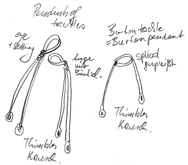
That would be my interpretation for the pendents so far: Pendents of Tackles Double Pendent with eye and seizing lower fore and main mast Burton Tackle = Burton Pendents Double sided tackle with **** splice. mizen lower mast, fore + main top mast Mizen topmast no hanger/tackle? Also still the question about serving the first shroud of the topmasts. Also aft mourn lower shroud as in later times? XXXDAn
-
A few questions about the shrouds on my Victory and her contemporaries. 1 - Steel and all the others state that the foremast and mainmast shrouds are fully dressed. Since this information is generally missing in Steels description for the topmast shrouds and mizen shrouds, I assume that these are to be left undressed. This leads to the question to why they were not needed to be dressed to protect sail and shroud like the lower ones? Also the French in La Creole some time later also dress the foreward topmast shrouds, as seen on archjofos wonderful build. Also Schrage describes the foremost topmost shroud as being dressed. Marquardt does not mention the dressing in the text but shows it in the drawings. 2 - What is the difference between Pendants of Tackles and Burton Tackles? Steel makes a distinction by saying" ..., but burton tackles are used on the mizen mast, instead of pendents of tackles." But Longridge and others use the term synonymously. Is the difference in Steel possibly that the pendents of tackles are like shrouds in a pairs with an eye for the masthead and the Burtons as a single strand on both sides with a cut splice? 3 - Steel does not specify Burton Pendents/Tackles for the mizen topmast. Correct? 4 - I was a bit confused at first about the "swifters", which according to Steel are put over the masthead between shrouds and stays. Then I found out that this refers to the rear shrouds, which are not like the shrouds a pair with an eye, but are one rope with a horseshoe splice. Correct? As always, questions upon questions, Daniel
-
Slowly and carefully we went on, and then the time had come ... ... both sides of the deadeyes were integrated into the shrouds and tidied up. Final alignment of the deadeyes angle comes when I tighten the lanyards. The angle is also almost right. I mean the mast, of course, the fighting top is hanging so crooked on purpose http://www.shipmodels.info/mws_forum/images/smilies/icon_wink.gif I now also have a good system for tying in the deadeyes. Materials, 1 set of upper deadeyes starboard and port, a cable 0.9 mm, lanyards with half of it 0.45 mm and the seizings with 0.15 mm. First assign all shrouds to the lower deadeyes. Secure with an auxiliary thread. It will then look like what you have already seen. For the sake of clarity, we will now continue with a single shroud. The deadeyes are easy to hold with pointed tweezers, the ends should ideally protrude at the back. A cardboard template on the chain board helps to maintain the correct height. One hand holds the shroud in the correct line to the lower target deadeye, a micro portion of superglue is placed at 3 o'clock in the groove of the deadeye, and by placing the protruding tips of the tweezers on the top edge of the template, the deadeye is pressed against the shroud at the correct angle of rotation. Then, if necessary, apply a micro portion of superglue at 9 o'clock and position the free end behind the shroud. Then close the eye with 2 knots. A little space must be left between the deadeye and the knot, as in a later phase 3-4 more knots must be added to the eye and the thicker lanyard must also be passed through there. I don't glue the two knots at this stage because I can still correct the eye if necessary. Then the lower seizing of the 3 ones of the free end is secured and aligned. Depending on the era and nation, the shroud and free end either run in mirror image or asymmetrically with the shroud directed towards the center of the deadeye and the free end running out tangentially and then tied on at the top. And then the lanyard can already be integrated and provisionally fixed above. Only when all the shrouds have been fitted in this way will the remaining turns on the eye and the 3 upper seizings be completed, see above. The final step will be to bring the lanyard forward over the deadeye under the knpt and tie it on above. It actually went quite quickly, was looking even enough and, above all, the potential for frustration was manageable. XXXDAn