dafi
-
Posts
2,433 -
Joined
-
Last visited
Content Type
Profiles
Forums
Gallery
Events
Everything posted by dafi
-
 Great work. Interestingly, when comparing McKay + Longridge with Steel, I noticed that Steel replaced most of the long tackles with normal double blocks. Only not those on the forestays, which are still listed there as with long tackles. I usually fix the fall with a half hitch between block and hook and, depending on the situation, either wrap the overlength in a bunch or wrap the rest around the fall, which I would do on the stays. XXXDAn
 -
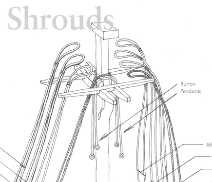
Hello William, congratulations for your persistence and the want to learn! If this is the mizzen mast the Slice is right, if this is the main or fore mast then the pendants should be looped over the masthead in a pair like the shrouds do. Here a cutout from Peterssen. As for the blocks, McKay apparently omitted them - as it was for many years on the V. in P. Steel is using Single 24 Inch for main and fore (15 and 36 in AOTS and the spreadsheet that I did send), and 11 inch for the mizzen. Also for Runner and fall that are hooked in there Steel uses normal single and double blocks, as for most of the literature there are long takle blocks mentionend. For your build there is a sprue in the standing rigging section called "Pendants of Tackles" 015-036with enough good blocks of the said size. Also the 11 inch for the mizzen and topmasts can be found there 🙂 I added a PDF with an overview which blocks to be found on what sprue, hope it helps. I did some more crosschecking on the matter of blocks and added some more blocks to fit for different rigging sources. All those that already did purchase blocks, there will be a new version of the spreadsheet and free "extension set" coming soon 🙂 XXXDAn Layouts Blockversand V3.pdf
-
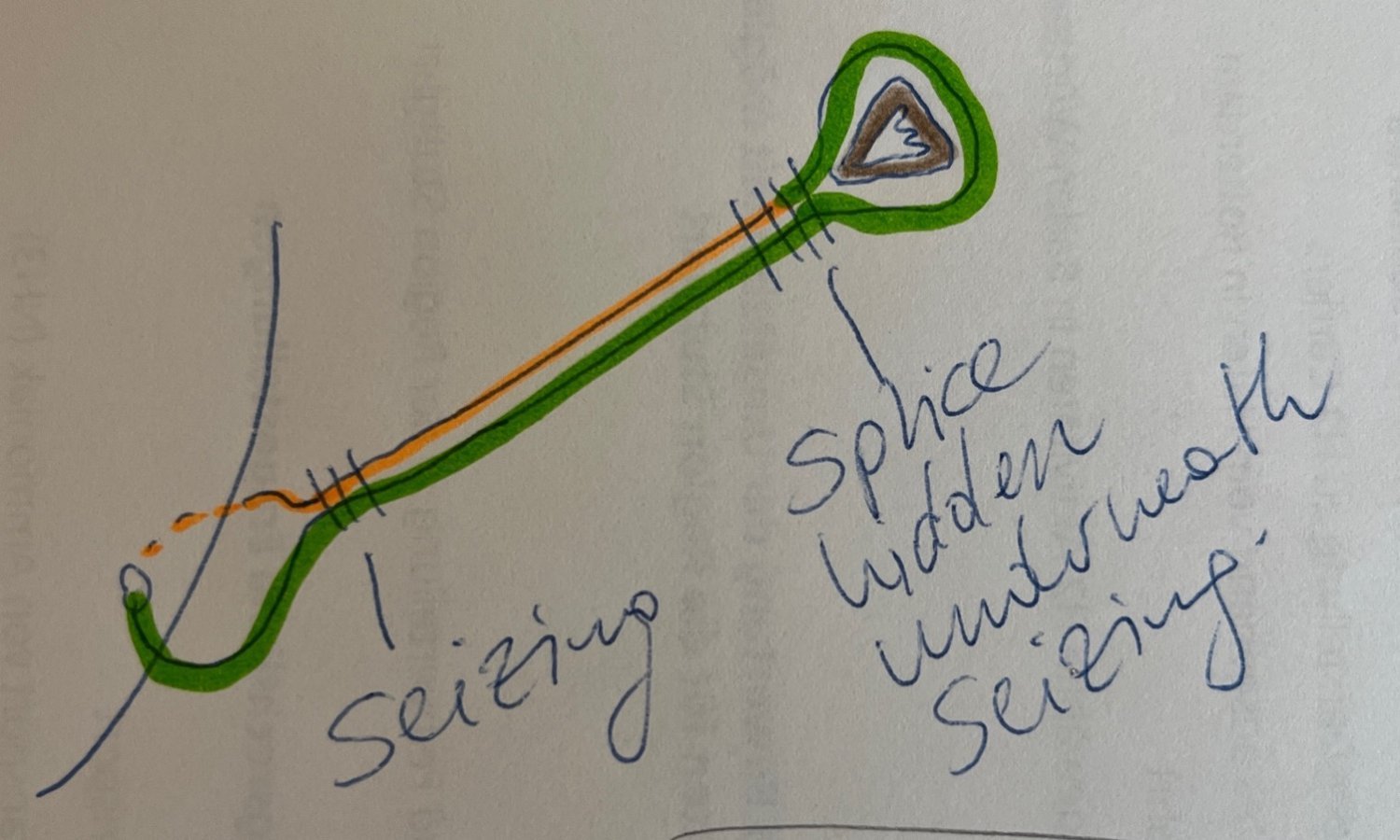
Laniard imho ok, but see my scribble for the rest. The joint of the ropes is hidden underneath the seizing. XXXDAn

-
Just a small warning for those who follow the sequences of my build: Please remember to put the shrouds before putting up the stays! My stays are up for test purposes, I will still have to reopen the lanyards take the stays off, fit pendents and shrouds and then finally reset the says and its lanyards 🙂 All the best, DAniel
-
Just a small warning: Before the main- and forestay can be set, do not forget to put up the shrouds! XXXDAn
-
Well done 🙂 For the blackening: I usually take a dry brush with black paint and go over it after assembly. Takes out all injuries in the blackening from the tools, adjustes the color and blends in with the other paints and also covers all possible white spots fron the CA 🙂 XXXDAn
-
Wonderfully done! Congrats! Please allow me a remark: The 3rd boobstay that splits into two legs is not the optimal solution. It is shown in Longridge and other literature, also it was featured for many years on the exhibut in P. The preferred solution would be to be fixed in a new hole just underneath the upper two ones. XXXDAn
-
Hello B.E. wonderful work, as always from you! Just rediscovered this thread and enjoyed your astounishing work. Small remark/question for the knot in the channel from fixing the the rudder pendants. In the most probably contemporary model of Victory LR0512 http://collections.rmg.co.uk/collections/objects/66473.html the pendants do not stop there but run through the channel boards up to the poopdeck to be secured on a clamp there. Is there a contempoprary source that indicates where the pendants were usually led to? Also concerning the small leather tube that protects the port lid lanyard: I had it alraedy in one of my models faked by a bit of white glue to give volume and a bit of black paint. looked convincing at my small scale. All the best, Daniel
- 648 replies
-
- 4
-

-
- Indefatigable
- Vanguard Models
- (and 1 more)
-
Yes, dafi knows how to do it, dafi hasn't forgotten anything ... ... ... ... the wrecking ball! What happened again? I always say it, my biggest problem is getting the big exhibit in P. out of my head. For almost 20 years now, I've been looking forward to those great special shoulder and quarter blocks that I discovered back then back there, building them exactly according to McKay and Bugler's plans and, in my exuberance, not even realizing that they are much rounder in the classic literature ... Thank goodness there are some people in my german pack and also here in the MSW who are not so obsessed and have a keen eagle eye and have pointed this out to me. Thank you! So I made new rounder blocks. I used this too to do some more research, as I was slightly irritated at the first pass when I noticed that these blocks on the foremast lower mast and topsail are all the same size, just like on the main mast lower mast and topsail. Thanks to you @druxey for reassuring me in theses sizes and confirming this on the basis of Steel's information. At this point, in response to a few questions, I would like to repeat the painting method: first, using an old disheveled brush, two layers of very thin paint in a darker brown, which is the base color. The thin paint makes it easy to get to the sides without pasting over the holes. The highlighting color in a lighter brown, applied with a dry brush, is applied on top. This emphasizes the edges and the depths remain slightly darker, which gives optical depth. And the deliberately uneven application of color keeps the whole thing alive and no longer looks like plastic. Then the grand finale: as the new round blocks are the same size as the old square ones, simply press the new ones back into the strop from the side and you're done. The same with the sheet quarter blocks, before - after :-) You see dafi still can do it :-) XXXDAn PS: All those of you that already got a delivery of blocks will get a free upgade of the blocks in question http://www.shipmodels.info/mws_forum/images/smilies/icon_smile.gif
-
Now I got, it Allan 😊 Bill is still at the hearts for boopstay and bowsprite shrouds. You are right, the lower hearts for main and forestay are different as the collars for the mainstays are single ones and the ones for the forestays are taken double. Here is the fixing of the Stays in my Model, the bowsprite gear is aready fixed.
-
The old Warthog 🙂 Just a comment for the collars of the hearts. Even though some assembly instructions indicate all 3 Harts together in 1 collar, it schould be 1 collar for each single heart, means 7 altogether. This is historically correct and believe me, even for the model building much easier than fitting all in 1 collar while levelling out the lengths properly 🙂 XXXDAn
-
Next, of course, was the combination of blocks with a shoulder block for the top sail sheet and a normal block for the lift on the yardarm. First the two blocks stropped together ... ... then still smuggled in with bright rope the loop for the horses onto the cleat and finally tied in the eye for the double block at the outside. First one side ... ... and then the second ... ... and everything for the lifts is on the yardarm 🙂 XXXDAn
-
I've been busy lately and haven't had much time to tinker. But the list of blocks to be used on the Vic and the corresponding rope thicknesses has finally been finalized. Time to check some of them out. As the blocks are sorted by yards and other locations, here is the block set for the main yard. Since the main yard has already been started, I've taken on its lifts. First the hangers. As usually served with white glue and black paint. The loop underneath the cap that holds the hanger together. And here the assembly on a spare mast cap. More hopefully soon. XXXDAn
-
Thank you Alan! XXXDAn PS: And before anyone asks: NO! The misappropriation of the derma-roller was not the reason of separation ...
-
Hello Alan, yes I am completely with you, most of the times the riveting is out of scale at small scales. At my Vic at 1:100 I refused for that reason for a long time to simulate the riveting until I found something in the shelf of the bathroom: a derma-roller of my then dear lady :-0 A torture instrument in my very eyes, I saw the other qualities, I disassembled one and gave a different distance for the spiky wheels and a new handle and then things kept rolling 😉 The result was quite like I feelt it should look like, very subtle to the naked eye, it gives a kind of structure that is feeling quite welcome on the whole of the coppering. I also opted for the naked keel. I know the basic flaw are the overscaled scales of the Heller kit, but over all it leaves a "good impression." XXXDAn
- 49 replies
-
- 10
-
-

-
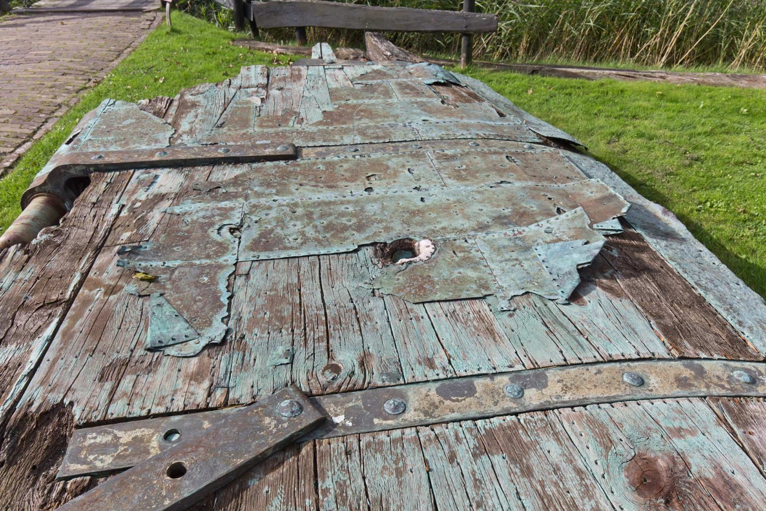
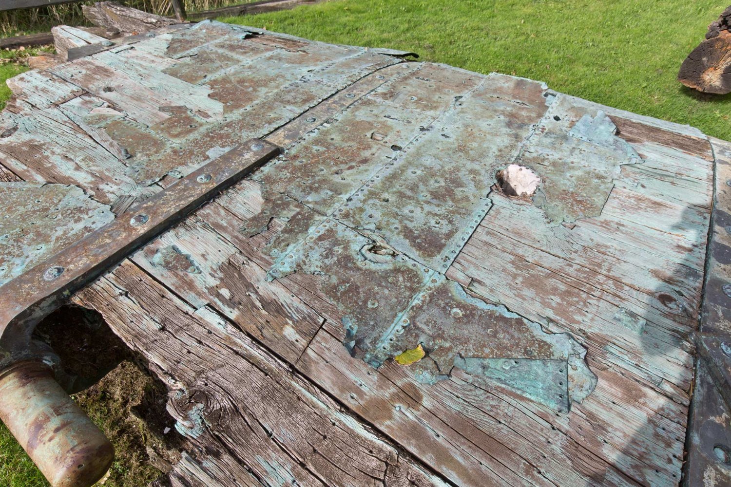
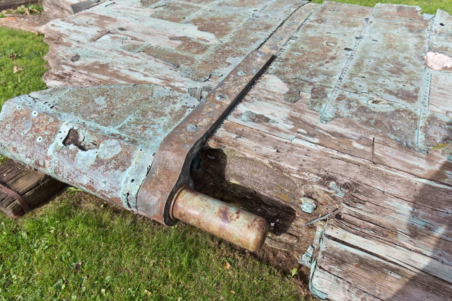
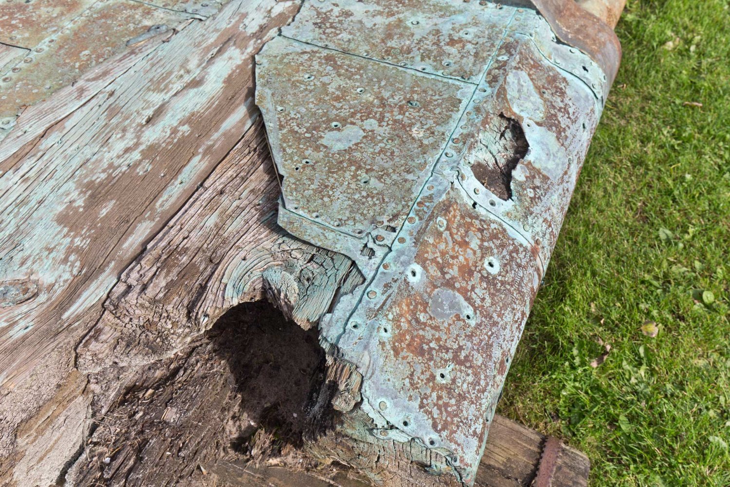
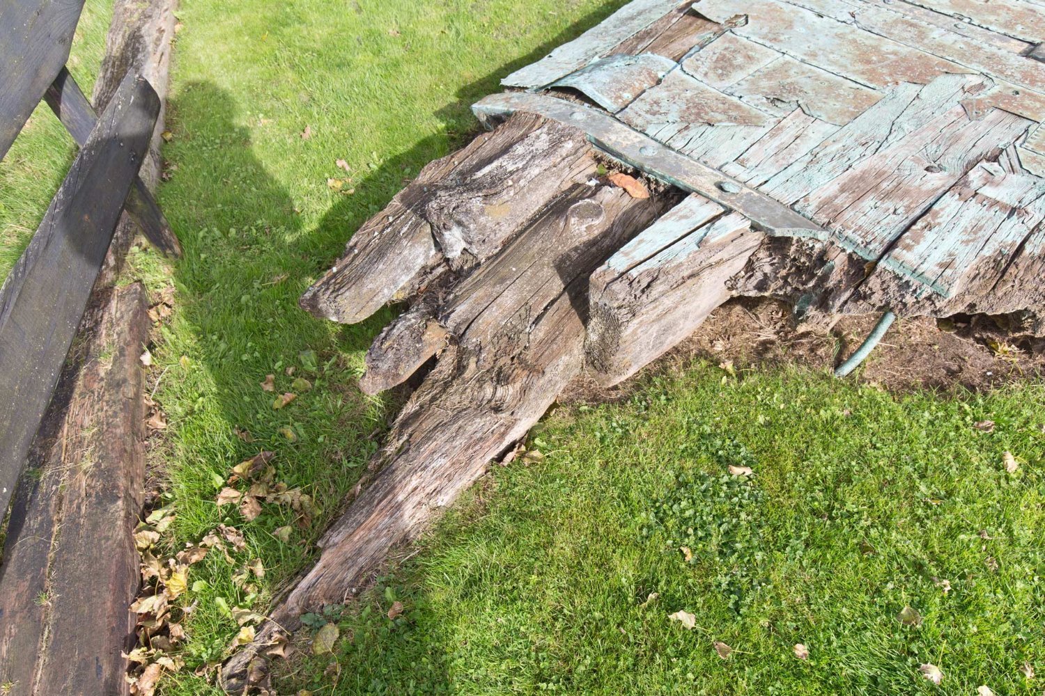
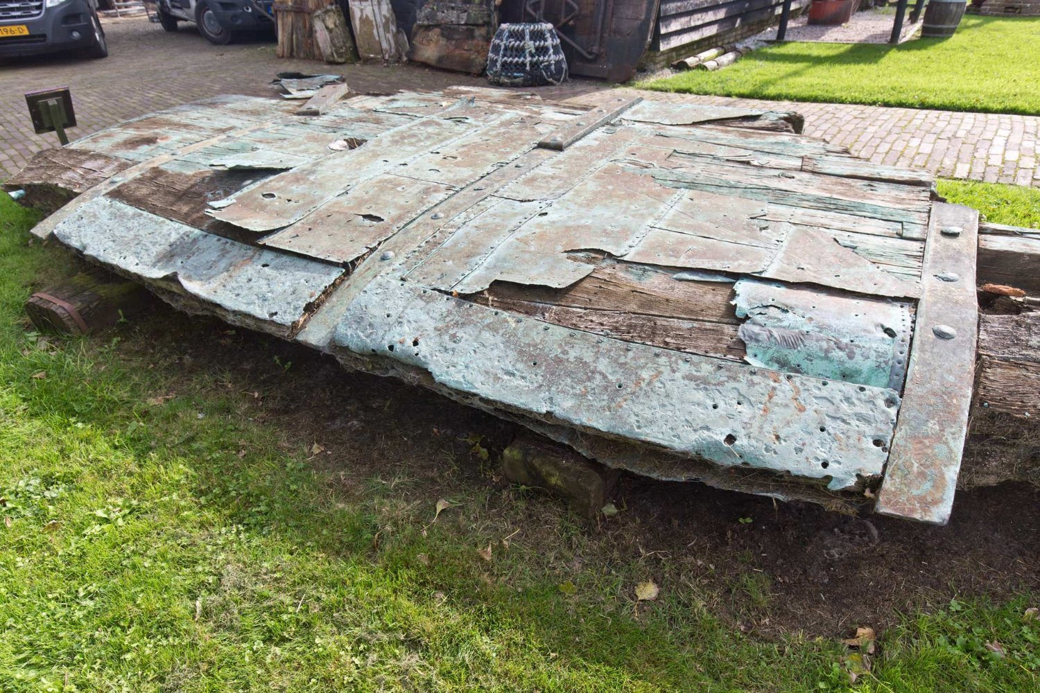
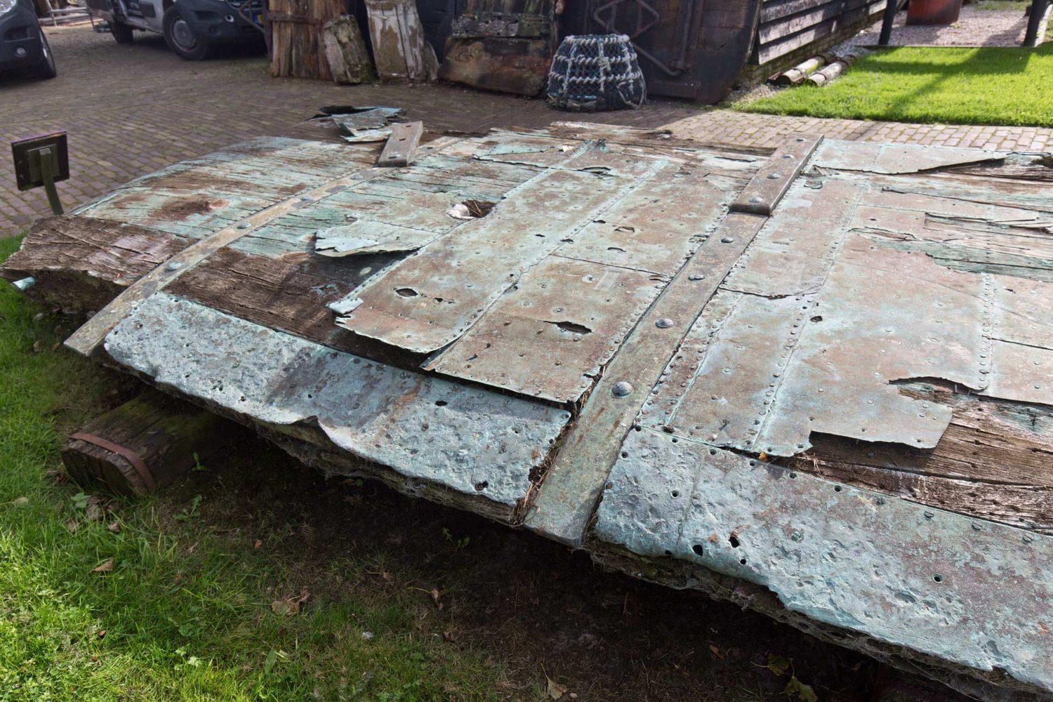
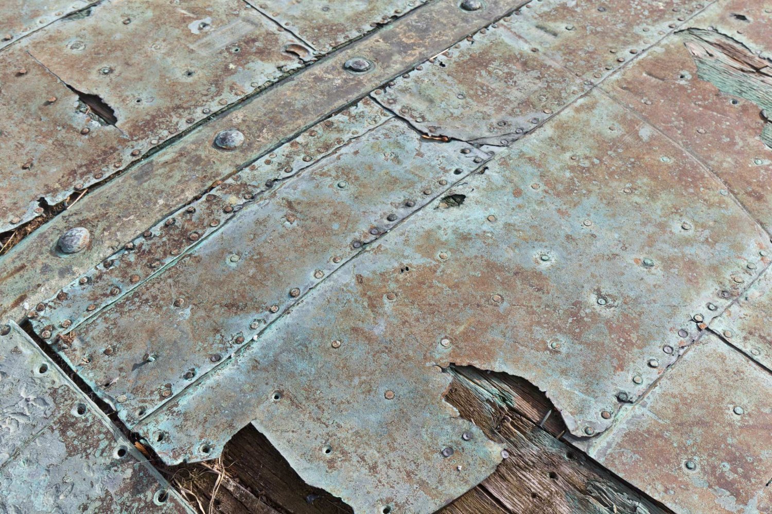
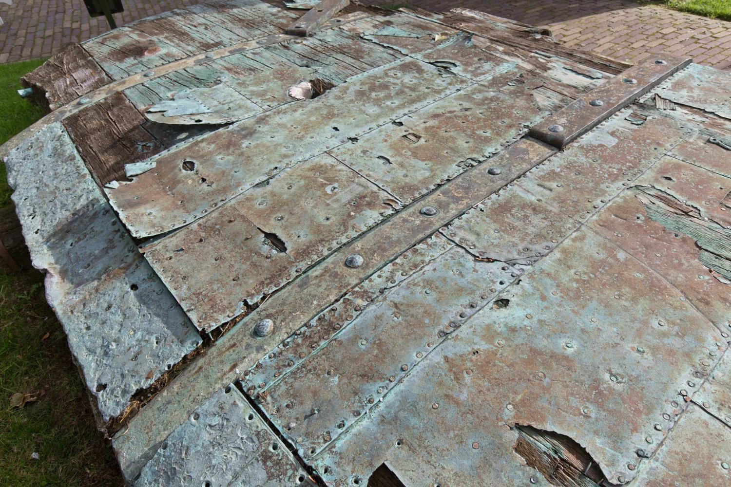
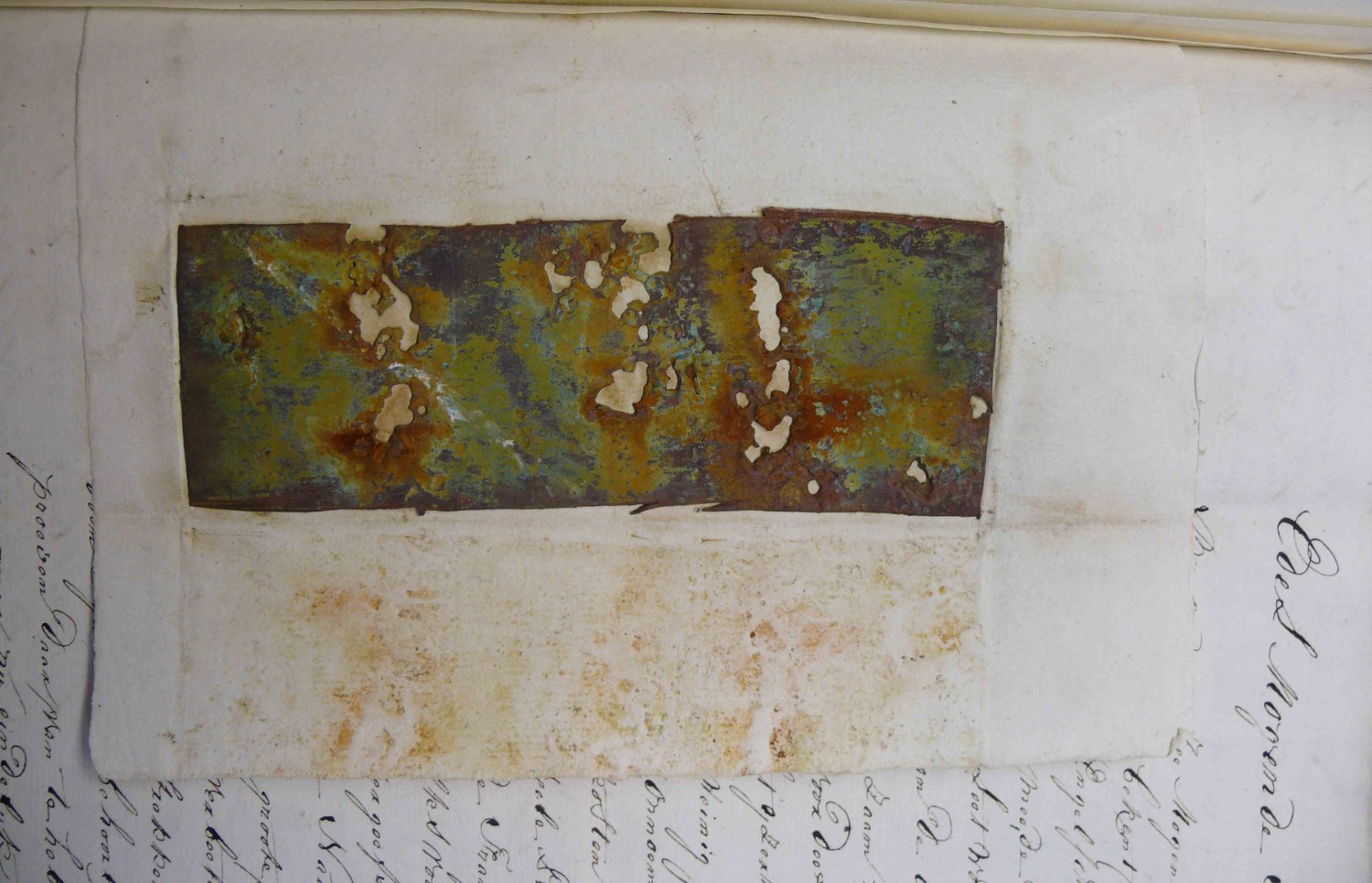
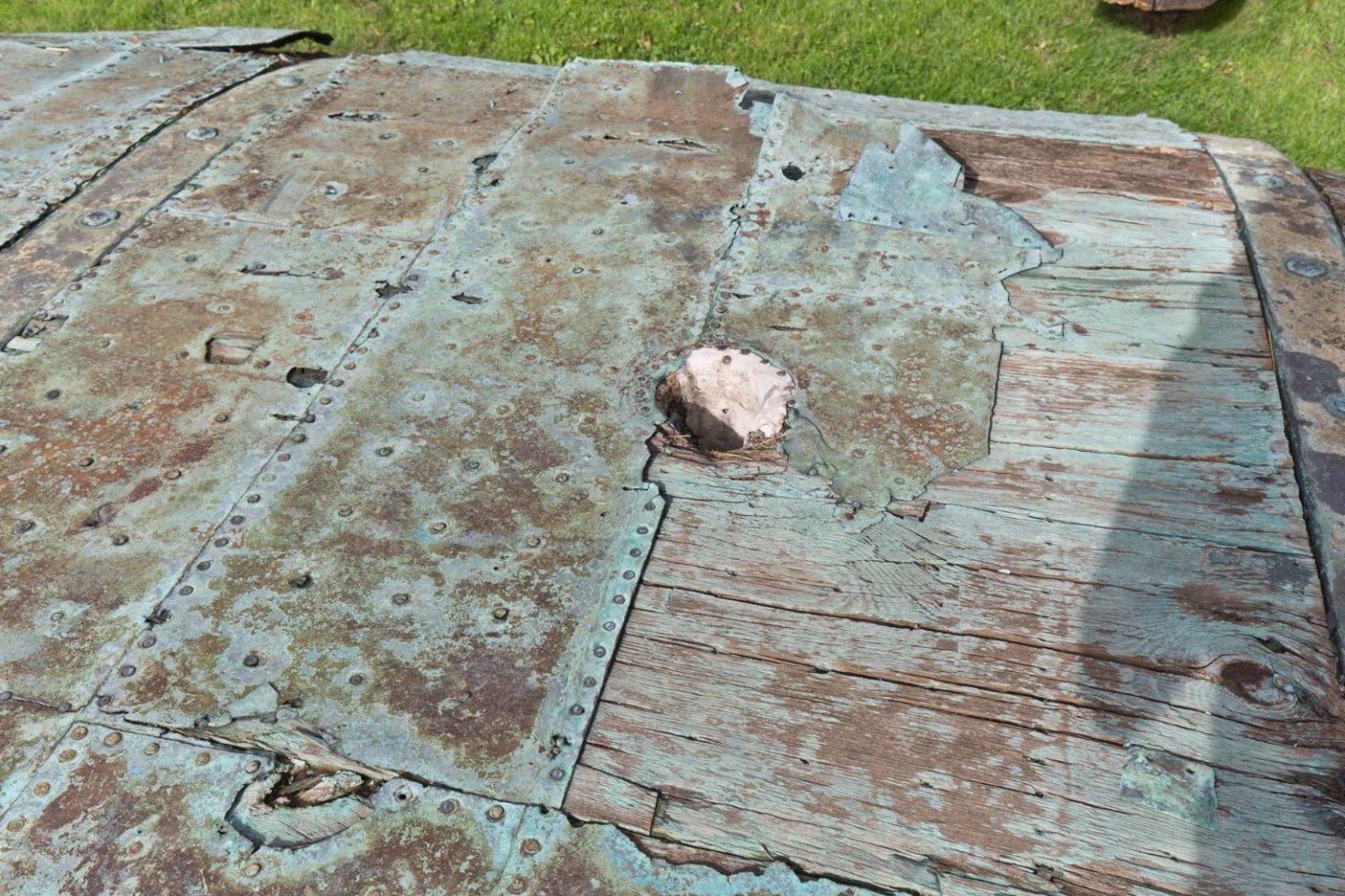
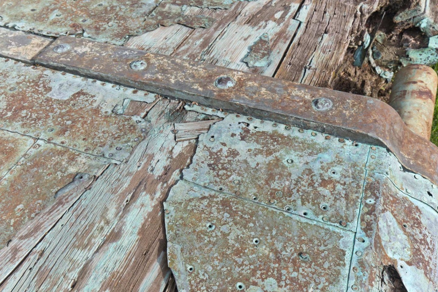
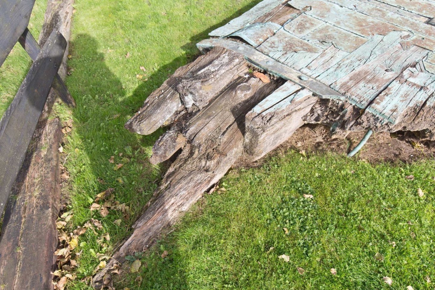
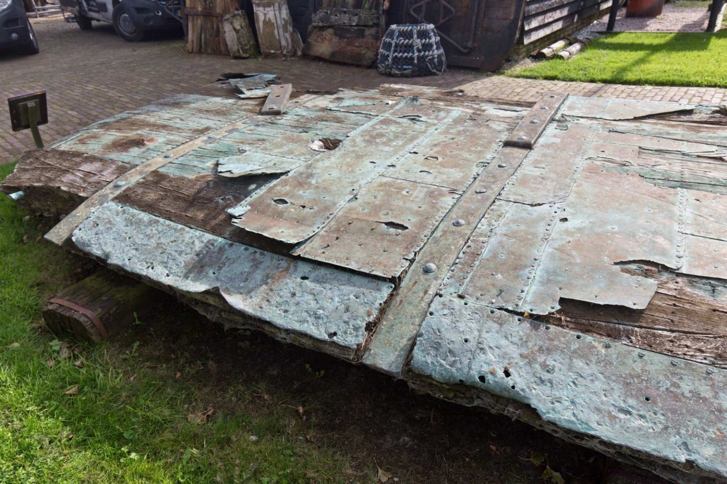
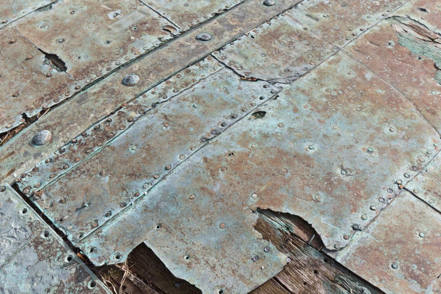
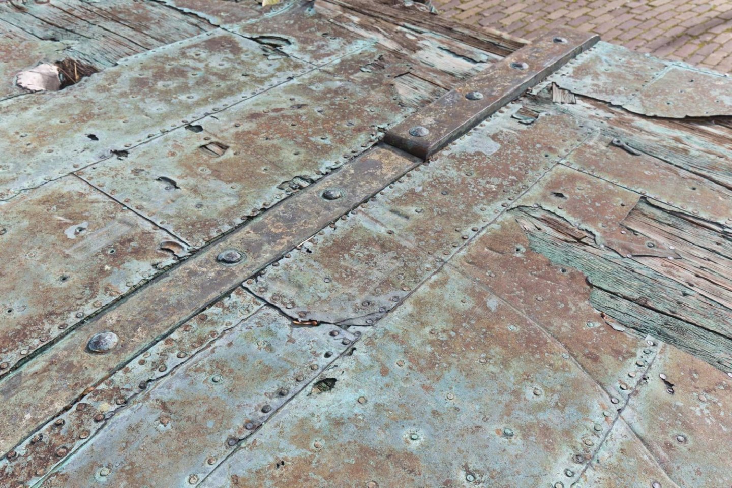
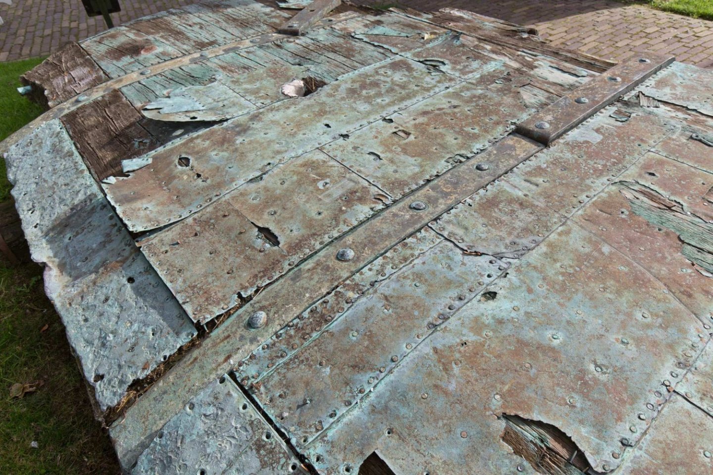
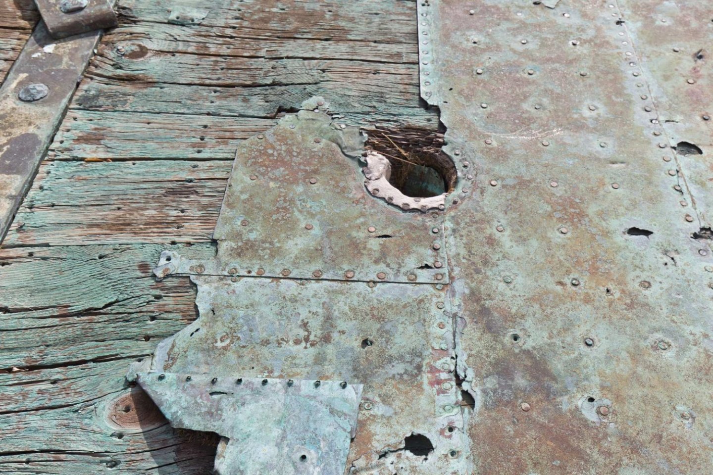
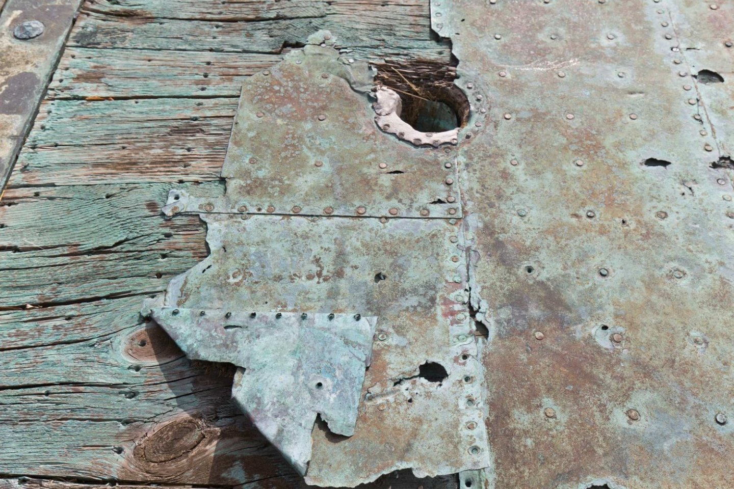
Thank you Alan, my pleasure! Her some more real old copper, seen in museum in Oudeschild Texel, where the famous dioprama of the roadstead with the dutch fleet is shown. Just enjoy the laying pattern, the adjustments in the edges and around the fittings, the patches and my favorite piece: the hole of the rudder jeer 🙂


-
History shows both versions, without and with coppered false keel. So pick one 🙂 We had another discussion concerning this topic, and it seems, that sometimes while recoppering the false keel was not removed and overcoppered. Lazy bastards 🙂 All the best, Daniel
-
And if you put a white drap under the whole area and strech it even towards you covering your lap, then also much less parts will not pay a visite in one of our paralell universes 🙂
-
Good start nevertheless 🙂 I would use white glue for wood from the DIY-department. Also use it as well as the black paint before binding in the heart. Good success, Daniel
-
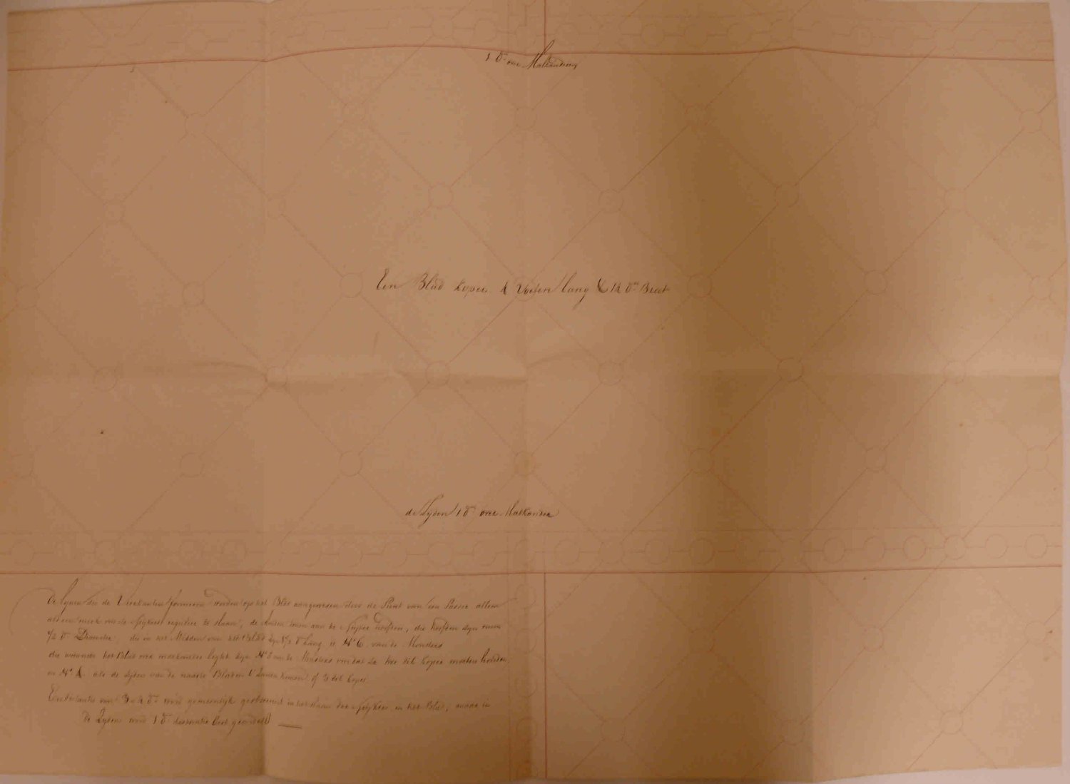
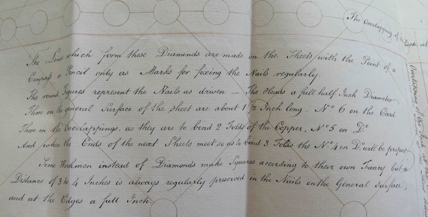
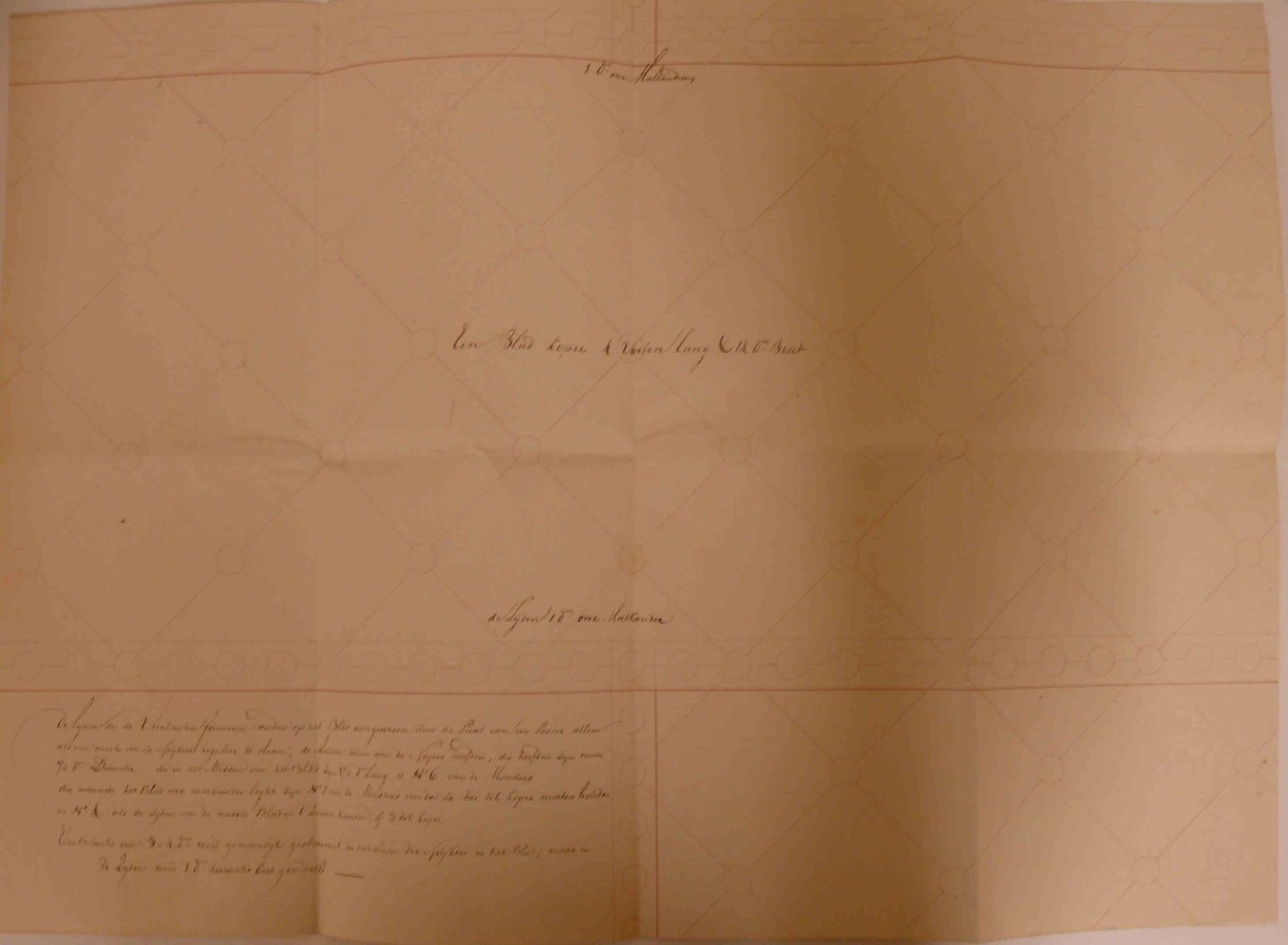
Nationaal archief Den Haag, Number 1.01.47.21 - Inv. Nr.: 112. I also added it to the entry XXXDAn
-
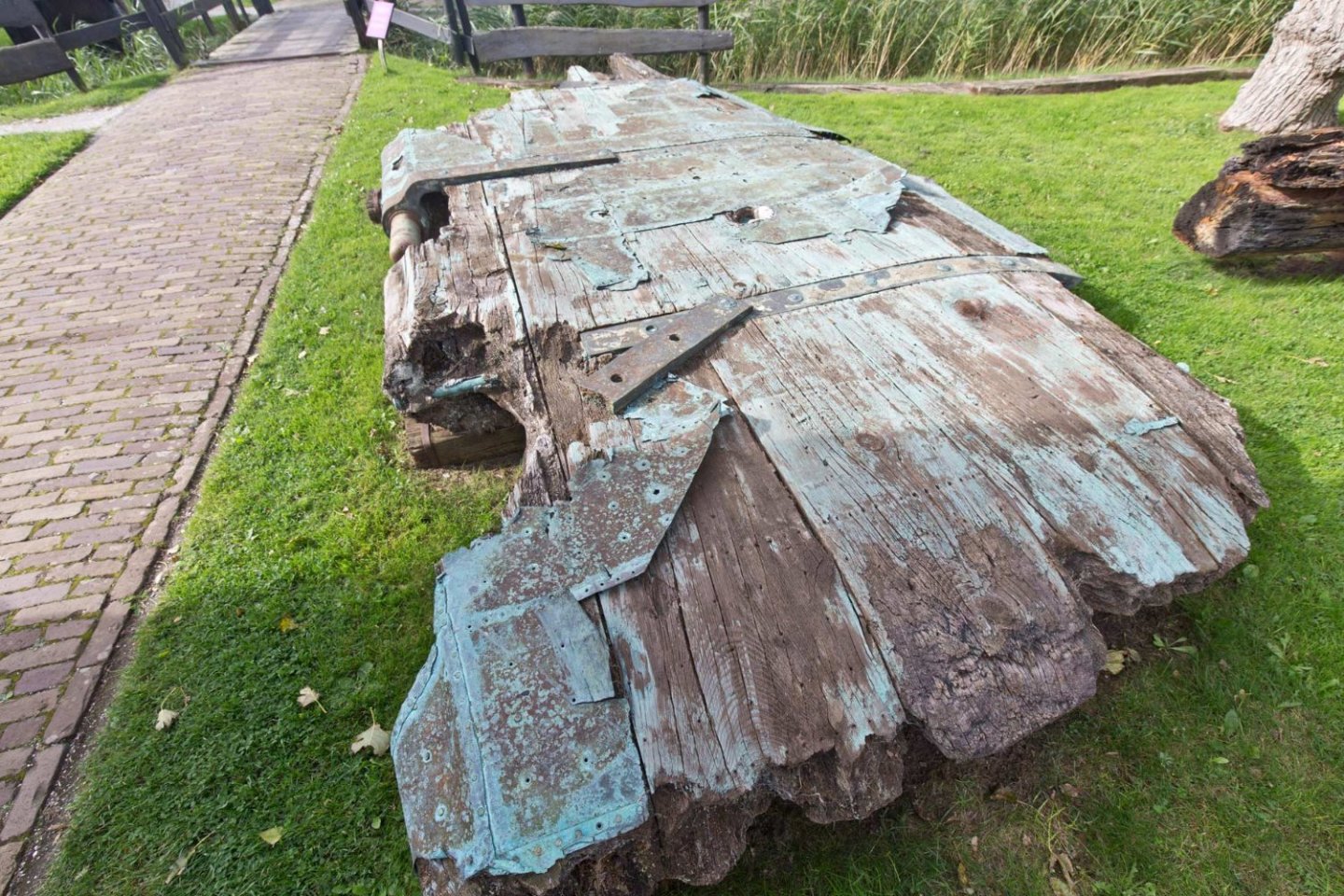
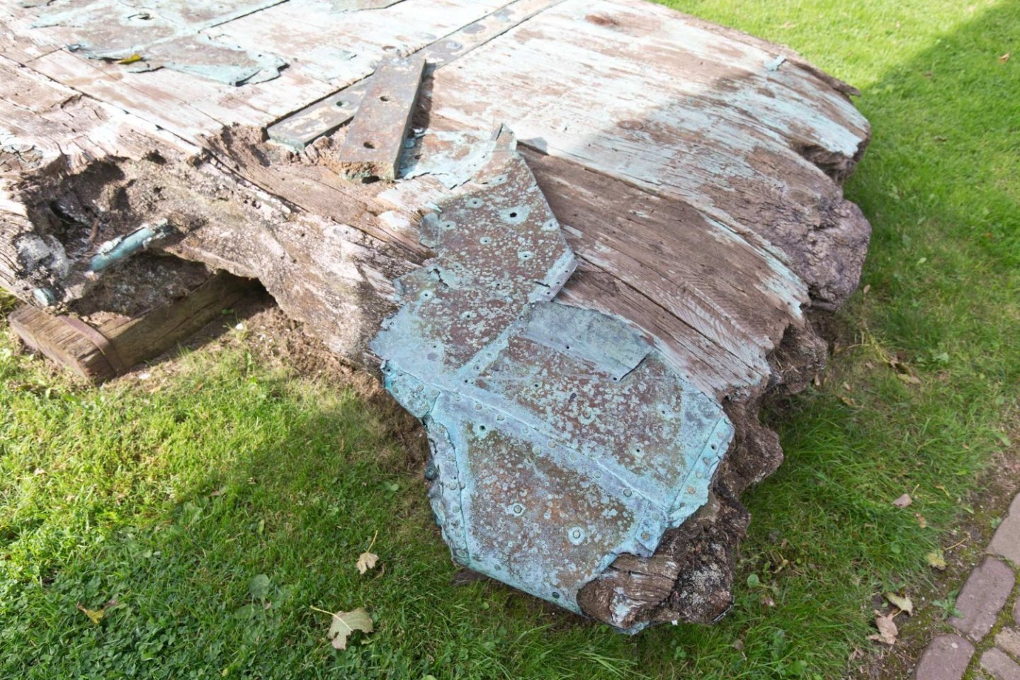
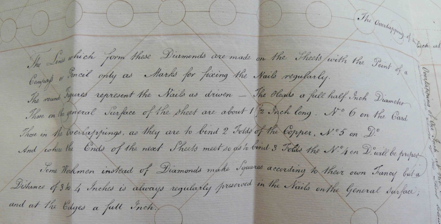
Here some additional remarks from my collection of historical copper: St. Georges rudder in Thorsminde, much patched but apparently mostely the lower plate overlaping the upper one. A spanish vessel lower one overlapping the upper one (drawn from a perished french forum) A picture of Bruno Orsel, unknown merchant vessel showing the same Nationaal archief Den Haag - Zugangsnummer: 1.01.47.29, Inv. Nr. 15 von ca. 1780. Die Platten waren 4 Fuß lang und 14 Daumen breit. Die Überlappung betrug 1 Daumen. Amsterdamer Maß. 1 Fuß 283 mm, ein Daumen 25,727.. mm. (Thanks to Werner) My interpretation of the thicker red line is that the upper overlaps the lower plate This could be an english original for the drawing above. Even with a copper sample 🙂 Nationaal archief Den Haag, Zugangsnummer 1.01.47.21 - Inv. Nr.: 112. San Francisco Maritime, National Historical Park, California, On permanent exhibit in the Maritime Museum is a portion of the hull and the rudder of the ship NIANTIC, which was beached at Montgomery Street during the Gold Rush and become a store and hotel. The vessel housed the boot shop of abolitionists. Intersting that the fittings on the hull were overplated, the fittings of the rudder were not ... Cutty Sark in 1872 after she lost her rudder, lower one over the upper one Historical picture of the Victory, lower over upper Just see how evenly it was layied 😉 Just like St. George´s copper. Not contemporary but nicely to be seen on Constitution 😉 Jyland, were old meets new. And for those who like films 🙂 Boston Tea Party Tours - Copper Cladding Begins | #11 https://www.youtube.com/watch?v=6TP5qGce...E78C06557ABDA9B Boston Tea Party Tours - More Copper Ship Cladding | #13 https://www.youtube.com/watch?v=YpVQ-EIGZW4 Boston Tea Party Museums - Copper Cladding | #17 https://www.youtube.com/watch?v=vZdH-r5a_HQ Boston Tea Party Museums - Fitting The Rudder | #18 https://www.youtube.com/watch?v=AO4uwCVIhwA Boston Tea Party Museums - Damaged Beaver | #19 https://www.youtube.com/watch?v=dcL2yVlri-w

-
The question I am having is: Did in Soleil´s days those ports were pointing foreward or aft as seen in Vasa? ... and the 2 last ports each deck are pointing aft. Nicely to be seen in the small reconstruction of the upper gundeck. Those guns can hardly be pointed the conventional way with 90° to the ship´s center line Also on "head chasers" on the upper deck are pointing forewards. ... thus avoiding the cathead-knee 🙂 Something that went wrong on the 1:10 model, where these guns have to be placed over the cathead-knees 😉 By the way, the lower deck guns have the same errata. XXXDAn
- 427 replies
-
- 7
-
-
- soleil royal
- Heller
- (and 1 more)