HOLIDAY DONATION DRIVE - SUPPORT MSW - DO YOUR PART TO KEEP THIS GREAT FORUM GOING! (89 donations so far out of 49,000 members - C'mon guys!)
×


dafi
-
Posts
2,426 -
Joined
-
Last visited
Content Type
Profiles
Forums
Gallery
Events
Everything posted by dafi
-
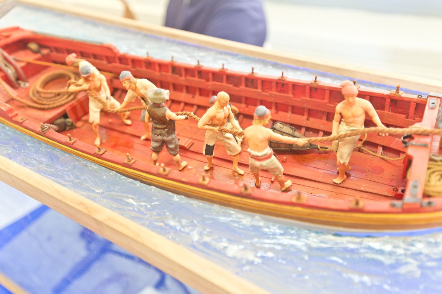
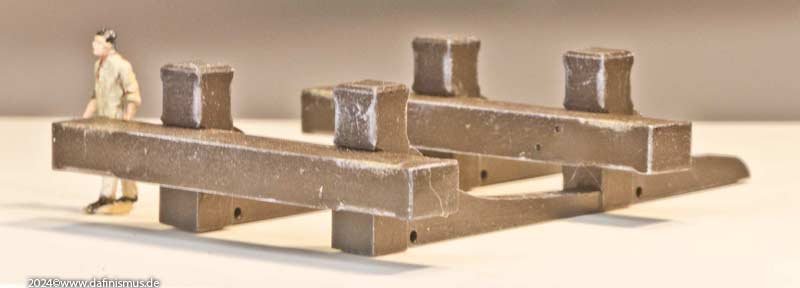
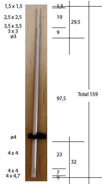
 Ok, let's talk about something we guys know more about: ze big guns. Or at least we think we do. In the past, model guns were mostly rotational pieces, and only larger-scale models were retrofitted with details such as ignition pans and coats of arms. These were custom-made or complex castings. With the printing the excuse of the effort involved no longer applies. That's why I finally finished the new guns for my Victory. And here starts a new point of discussion about how to present the guns. Not saying that the classical we usually show is wrong, but as an opener for mind and possibilities. Just to stir things up 😉 The version we usually show is with an exposed touch hole and without a tompion is simply how we know these things from museums and recovered from wrecks long time ago. But in real seafaring life this appearance was probably rather rare, it was probably mostly different: There are enough orders, records and wreck finds that describe the guns as most of the times ‘loaded’ during the period of 1800 and before. This also means that the powder charge stored inside the barrel had to be protected from water and moisture. For this purpose, tompions, simple wooden turned parts, were used as plugs at the front. They can be seen in many paintings, mostly white. The sensitive touch hole also had to be protected. Lead covers were used for this purpose, which protected the touch hole of dirt and, if the gun was equipped with one, the gunlock, and above all protected the hole against fire and sparks. When the gun was made ready for battle, the tompion was removed as late as possible and the cover of the touch hole was removed also only shortly before the shot was to be fired. Thus, in real life, there were mainly the following 2 conditions: - Stowed, lashed down, run out with cover over the touch hole or gunlock and with tompion - Shortly before firing, without cover over the touch hole or gunlock and without tompion Here we have the triad of touch hole, gunlock and cover in comparison: And here are the five gun sizes required for the Victory: 32-pounder medium lower battery deck, 24-pounder medium middle battery deck, 12-pounder long upper battery deck, 12-pounder medium aft, 12-pounder short quarterdeck. The classic ‘pure’ representation with open touch hole With gun lock. It is worth considering that the tompion could also be set if the enemy is not yet within firing range. And with cover and tompion. I adapted the colour of the lead covers to the artefacts from Thorsminde. The same applies to the fastening holes. This also results in the rear fastening via the ring, as all other types of fastening would slip off. The colours of the tompions – natural wood, white, red – are taken from the artefacts and paintings and should, of course, be uniform on the model. The wood-coloured ones were probably the most common, as the tompions were carried as prefabricated spindles in sets of about a dozen and simply sawed off as needed. I doubt that they were painted every time. Side discussion: Also this involves in my humble opinion the presentation of the tackles. If stowed it is clear that those have to be properly set to hold the gun, plenty of drawings show this. If ran out but gun secured (Touch hole and muzzle protected) those tackles should be secured too but probably not laying on deck. If ran out for "clear for action“ (touchhole and possibly muzzle protected) the tackles should be open, but secured on the carriage, the free ends in a way that it wont become knotted. And just straight before the shot: no muzzle, gunlock or vent hole open and the tackles be held by the crew. Is there any place for the nice spirals we like to show, especially with an tackle not made fast? Try this in real life and the guns will run amok at the first wave ... To sum the theme up, here are two scale pictures of the barrels shown above 🙂 Enjoy 🙂 XXXDAn


- 4 replies
-
- 14
-

-

-

-
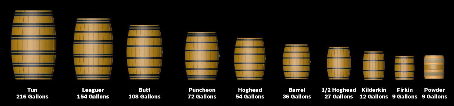
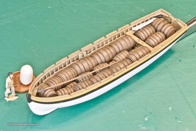
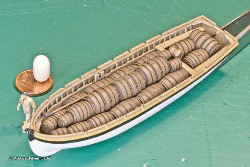
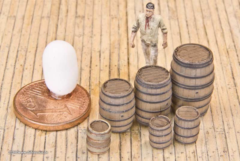
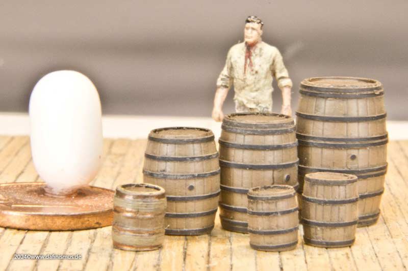
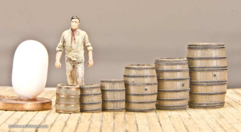
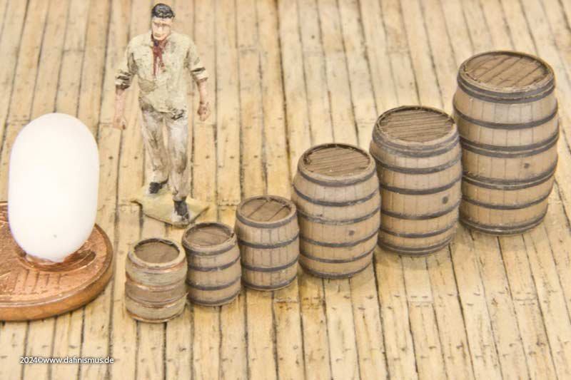
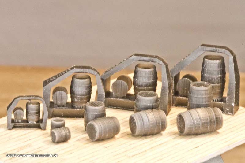
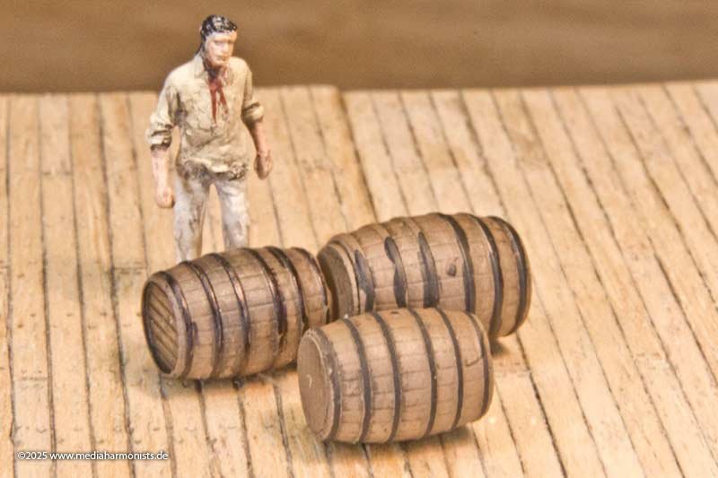
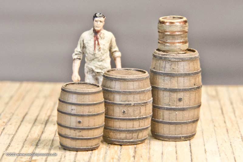
Next the barrels were continued. The number of hoops is interesting here. As an average layman, one would assume 4. However, Nelson's brandy leaguer shows a completely different number, and the double hoops are particularly interesting. I found several references to the fact that larger barrels have a double hoop at the top. So once again, nothing with once programming 1 barrel and scaling it to all sizes 😉 Each barrel format is unique, and I have attempted to develop a reasonably plausible number of hoops. After all, a 675-litre Leaguer weighs over 0.8 modern tonnes, so there is a considerable amount of self-weight to bear, especially during transport when dynamic forces are added. The result was a nice family picture: The 1.55-metre-high, 104-cm-diameter tun is the largest in the series, but I have not yet come across it in a maritime context, probably because it is too unwieldy. The smallest here is the firkin, with a capacity of 9 gallons, a height of 56 cm and a diameter of 43 cm. The powder keg on the Invincible has almost identical dimensions and, in my opinion, is a firkin with special hoops. The picture clearly shows that the size range of the different sizes could be reasonably accurate. Using this overview picture, I was able to compare the shapes of the different sizes. And here are the next samples of the barrels. The differentiation between the various number of hoops results in a pleasant visual impression for eye of the beholder 🙂 The selected sizes are, in descending order, leaguer, puncheon and hogshead, as these are always mentioned when stowing the hold, plus the kilderkin as it is a basic measure and the smaller firkin for boats and as the probable size of powder barrels. The stacking in the boats is based on historical data, so special launches for first and second rates could hold 14 to 16 leaguers, which is a mere 8 to 10 modern tonnes in weight. I dare to doubt how much freeboard was left, but perhaps there wasn't as much heavy stuff in there as liquids ... XXXDAn

-
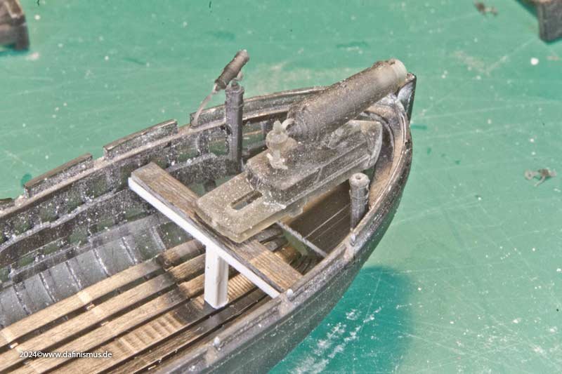
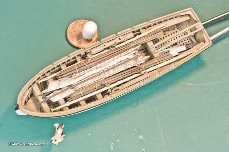
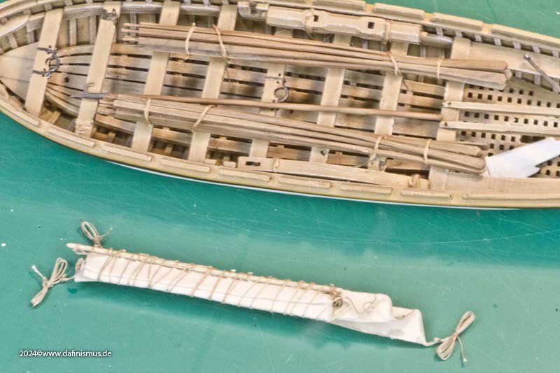
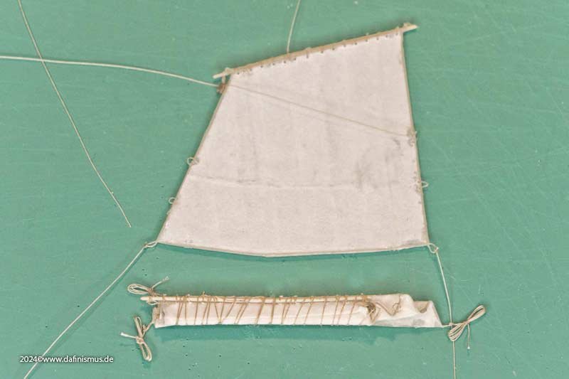
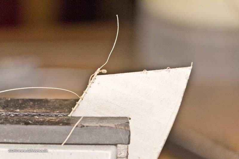
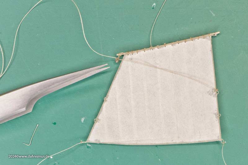
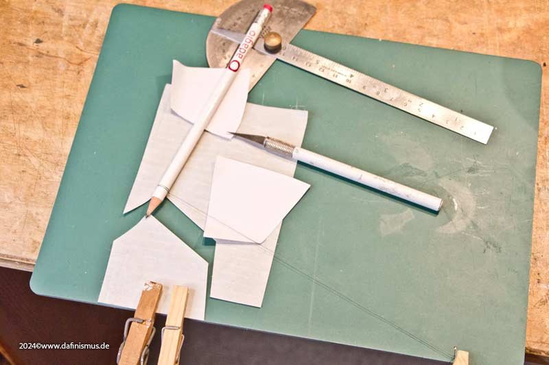
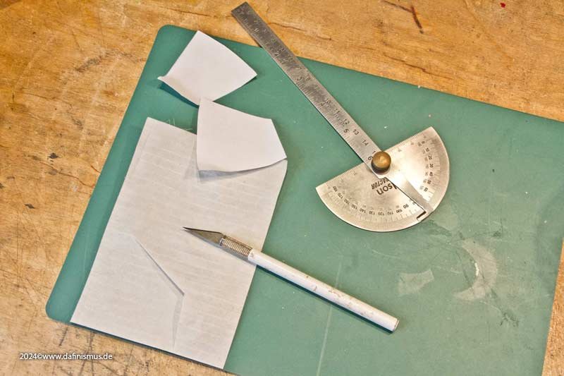
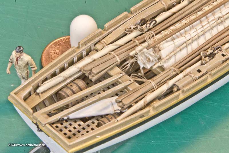
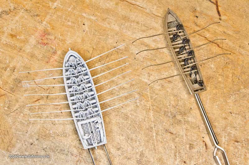
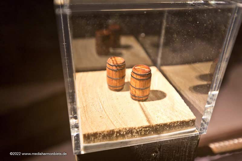
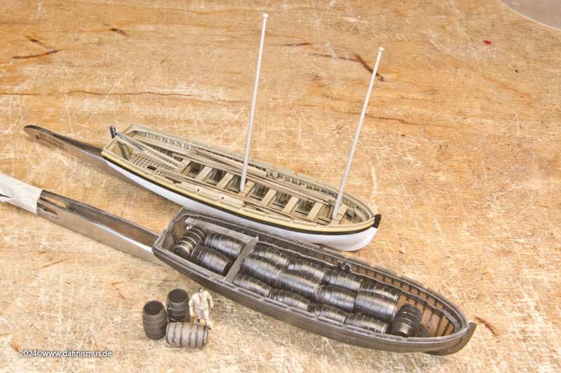
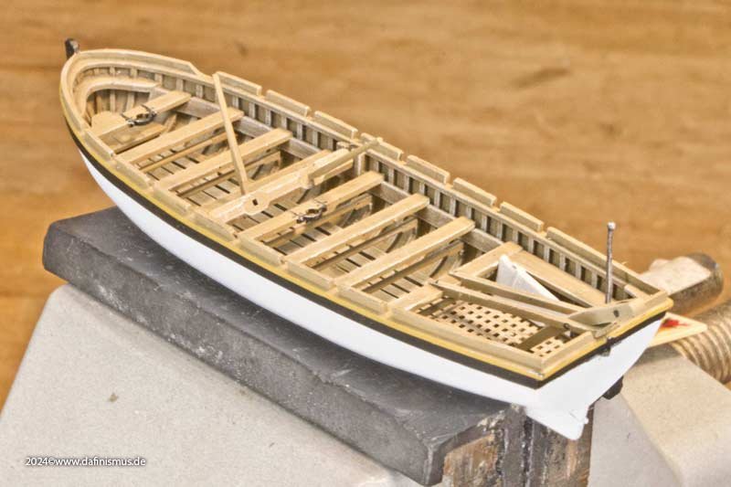
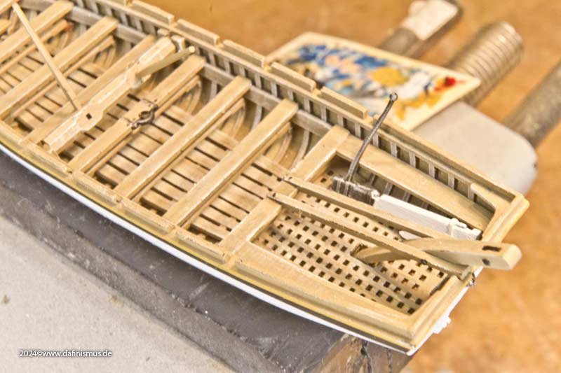
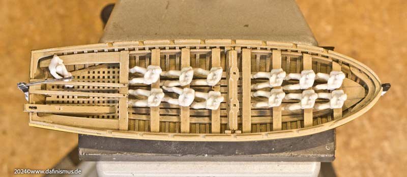
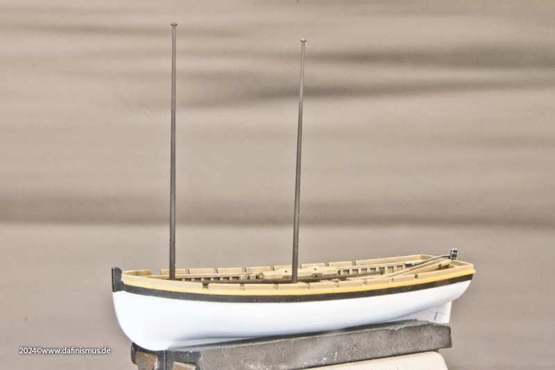
And we continued with the lugger-rigged version of the large launch. First came the masts. I took the measurements from W. E. May's summary, but they also correspond fairly closely to the French measurements. The strength of the lugger rig is its simplicity. Insert the pre-rigged mast, hook in the pairs of backstays on both sides with the standing end, hook the tackles in the middle, and belay the free end. The halyard of the sail is already sheared through in the masthead, so the sail is immediately hoisted, the tack, sheet and brail are secured, and off you go. In my scrap box, I charmingly found a sample from my sandwich sail tests from 2017 – yes, I actually keep such things for that long – and the sizes I need fit quite well, even avoiding the messy areas. I developed the material back then to combine the advantages of fabric as an elastic material and paper for a more true-to-scale surface. Thin strips of restoration repair paper are ironed onto both sides of a layer of silk to create a sandwich that resembles closely the visual properties of the sails. It is also unbeatable for folding and stowing. However, at the time, I did not yet have a model that was ready for me to use it on ... I took the angles from Steel's drawings, but I had to mark the radius at the bottom – one of the differences to French sails – with a pen and thread, as the radius is larger than my templates. I shortened the furled sails by approx. 25%, i.e. below the lower reefing band, which I had also omitted for this purpose. The surrounding leech was glued on and the eyes for the brails were added. If necessary, I'll even clamp a sail in a vice 😉 And then it was time to fold and fiddle around. And then it was adjusted to fit the storage space. Together with the masts in place looks quite cheerful and full. Two barrels have also found their way there. Who can find them? It's great to finally be able to use the sails developed eight years ago in a model myself. Some modeling friends have already impressively demonstrated their potential. Thank them for that. And I'm already testing out the next crazy ideas for my boat collection... XXXDAn


-
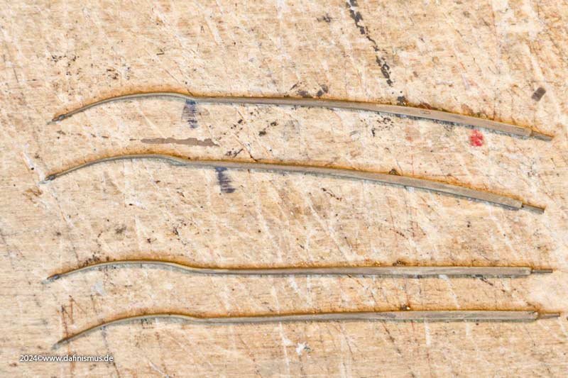
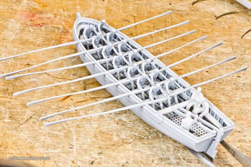
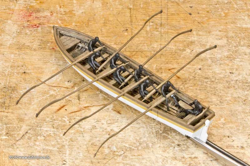
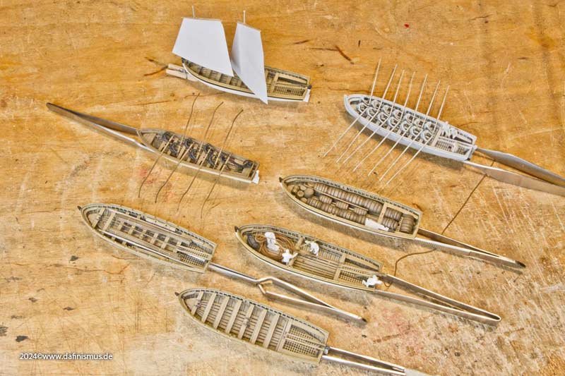
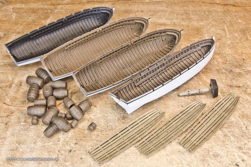
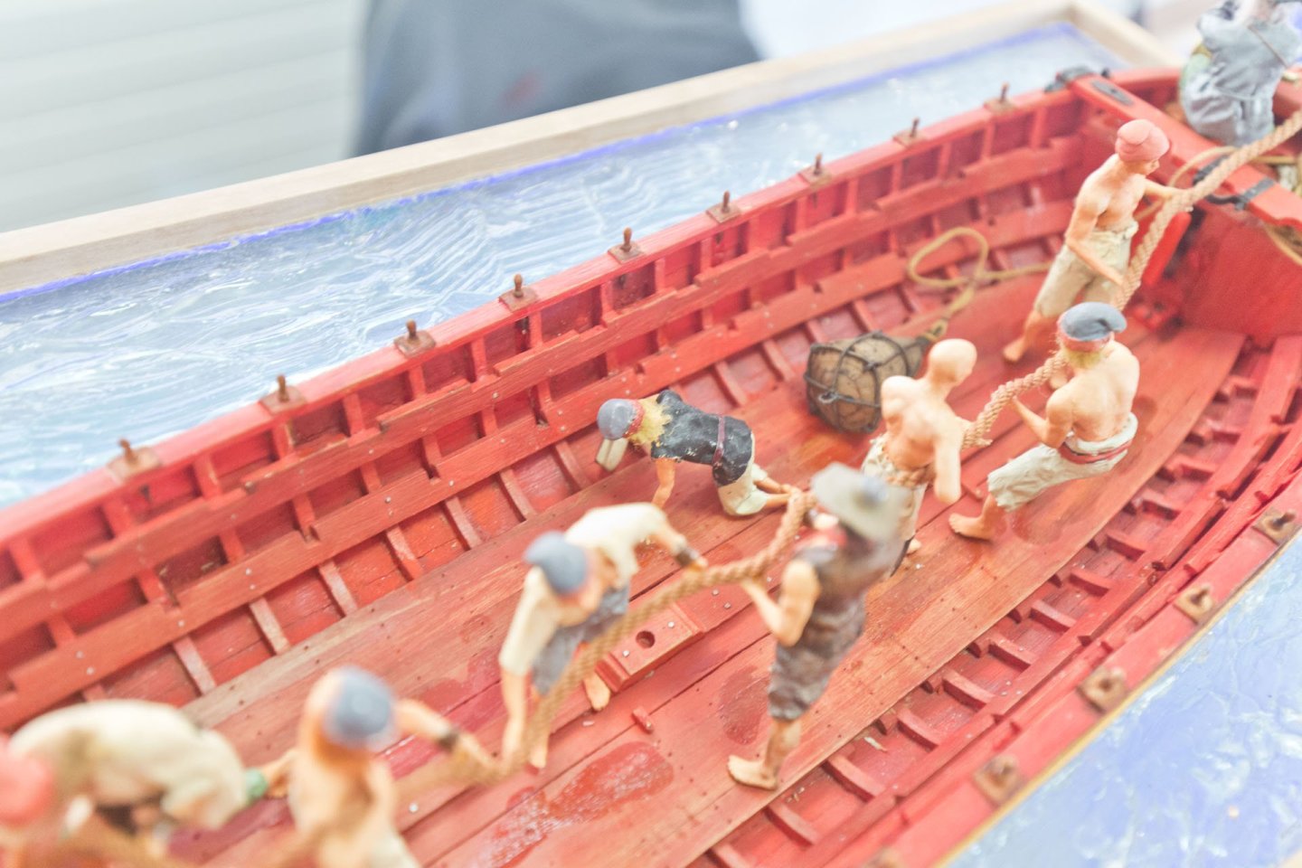
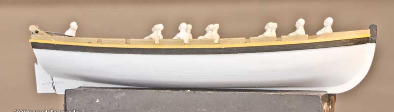
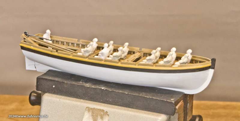
More on the casks soon :-) In the meantime, a whole small flotilla has emerged from my 32-foot launch 🙂 The 7-oared pinnace is in a race with the fully loaded 14-oared launch, which has to pull the fully loaded launch with the water barrels. Next to it is another boat with fully stowed equipment and one where the launch is helping to weigh anchor. And of course a setting with set sails. Always the same hull, but with different contents and task each time. More on the individual deployment options soon. It remains exciting. Here is the comparison one more time ... ... of the single-banked pinnace with the rowers always sitting on the opposite side ... ... and the double-banked 32-foot launch. And another little tip on the technical side: And I always propagate not to cold bend resin parts. After painting, the oars got quite a bend in the shaft. That's why I briefly dipped the parts in hot water. You could really see how the parts straightened out in the water within 2-3 seconds by themselves. Like memory metals, really strong 🙂 The bent parts at the top and the hot-bathed and straightened parts at the bottom. The fact that the far left side still has a bend is not a mistake, but the curved rudder blades of the small and medium-sized boats. XXXDAn And I still have 2 boat shells. ... what do I do now, what do I do now ...
-
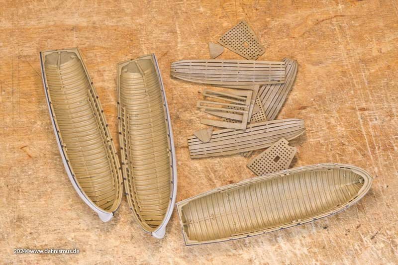
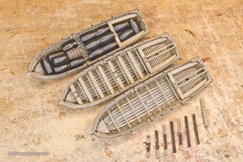
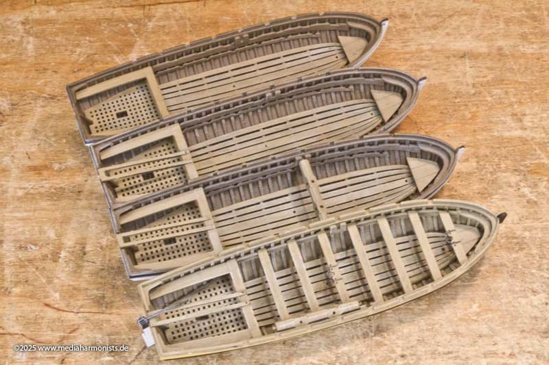
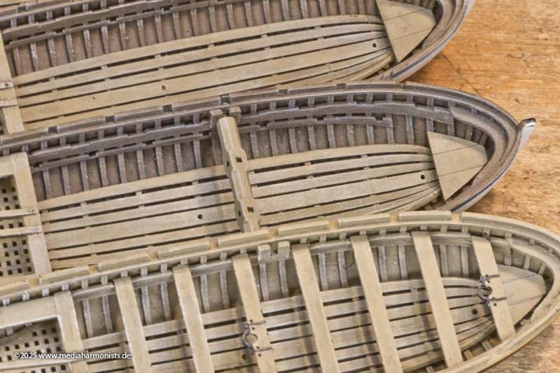
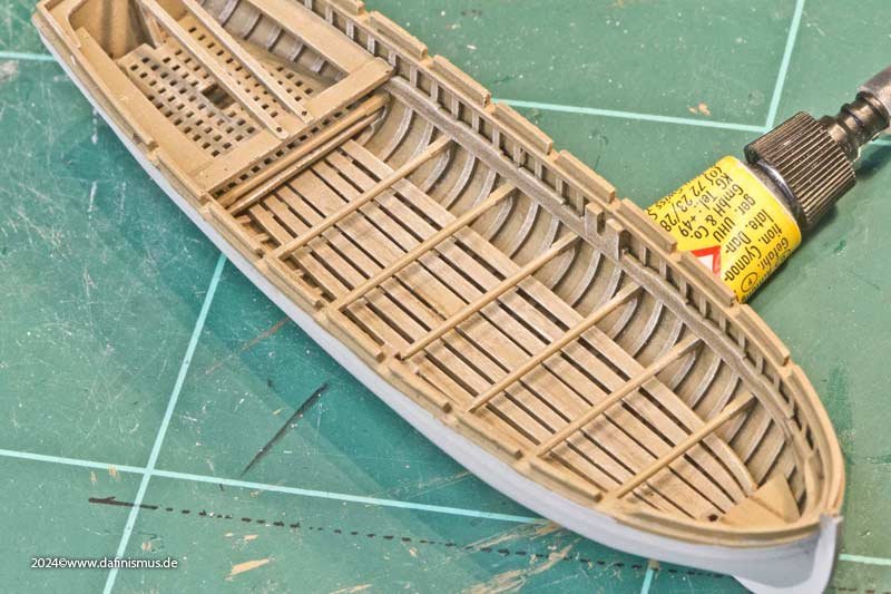
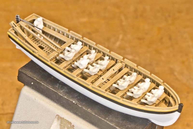
At the same time, work continued on the boats, especially on the 32-foot launch. The nice thing about printing is that you can simply repeat, so suddenly there were 4 hulls in front of me. What am I supposed to do with them again? The little devilish voice inside me then came immediately: Build it! Build it! Well, that's the way it happened. Here are the 4 steps of the interior: Priming black to prevent flashes, dark brown for the inner body, thin black ink for depth and usage, and white drybrush to bring out the textures again. On the other hand, I painted the interior parts with a lighter shade of brown, inked and brushed them to emphasise them a little. It could also have been interpreted as different wood. But when I looked at it ... ... and compared it with the first launch at the front in a completely lighter colour ... ... it looked too much like a toy to me, and the dafi had to do what it does best - tear it down! - and everything flew out again ... ... and the inside of the boats has been coloured lighter. Fits much better now http://www.shipmodels.info/mws_forum/images/smilies/icon_smile.gif Here is a picture showing how the barrels fit - that's easily over 7 tonnes of weight -, in the middle the rowing version, and the third one still without thwarts , where you can see the height of the stretchers above the inner floor. Then you can also see that the rowers' feet would otherwise have been hanging in the air and intensive pulling would not have been so successful. So that I don't always get the thwarts mixed up, I have given them markings on the underside. The stretchers too, by the way. XXXDAn
-
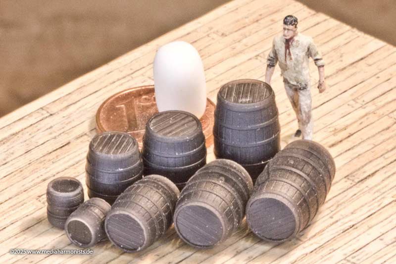
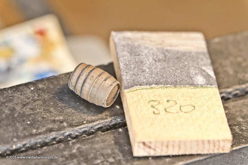
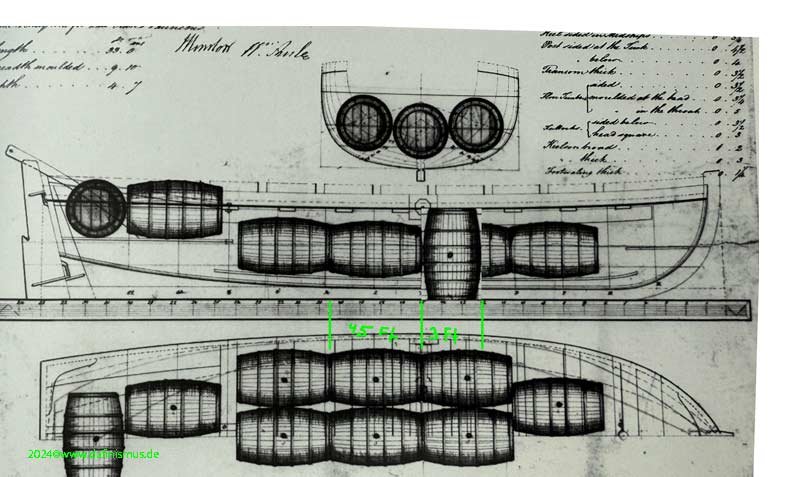
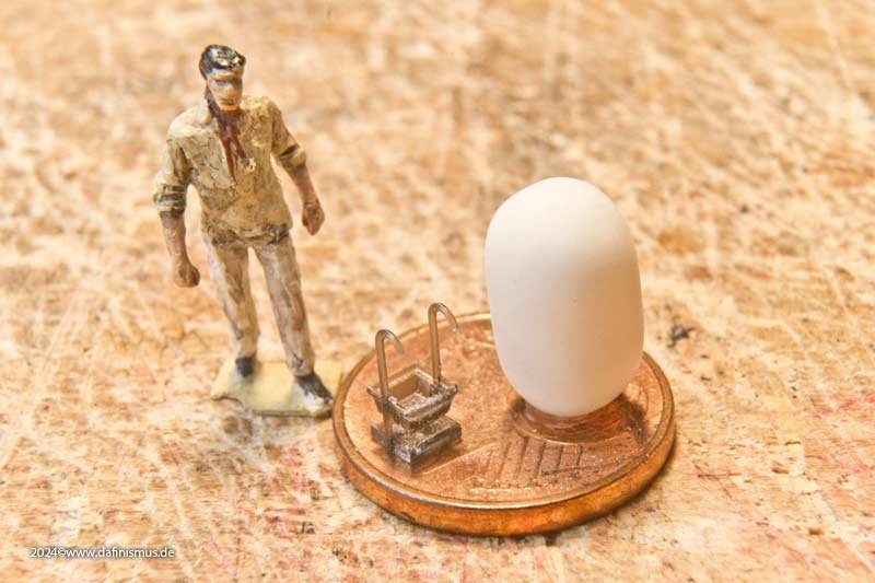
And once again I've made a mistake. This drawing from 1815 shows the loading of the large launch with barrels of drinking water. And so, of course, I had to know how big the barrels were in order to put them in my launch. These large barrels are so-called Leaguers with the equivalent of 480 liters. So with wood, they weigh over half a ton. And then 14 of them in the boat, making well over 7 tons. The research was somewhat difficult, as the volumes are often mentioned, but not the exact dimensions. In the meantime, I have researched the sizes of the whole family more or less reliably, so that I was able to start on the models. Here are the 3 sizes for the model: Leaguer 480 liters, Puncheon 318 liters, Hogshead 200 liters and a small powder keg. Each in three parts, as I don't want the supports to be visible as usual. Family picture with avatar. And after priming and inking came the challenge: blackening the hoops. At the back right was with the brush. On a good day, I get a few hoops, but then it's all over. Okay, that wasn't a particularly good day anyway. So I tried the back left with a felt-tip pen, which was better, but still uneven and above all an unpleasant metallic-reddish sheen. And in front a completely different approach, because I remembered that the prints are made of black resin. I quickly tried to see if sanding the hoops worked, and lo and behold ... ... it works like a charm! The powder keg was given its copper hoops and light-colored withy rings and joined the others. No iron hoops on purpose, because they could cause sparks and that would be really stupid. The copper is also nicely embedded between the withy rings so that it doesn't stick out. There are wonderful artifacts showing this, recovered from the HMS Invincible, which sank in 1758. And that brings us very close to what I wanted 🙂 XXXDAn
-
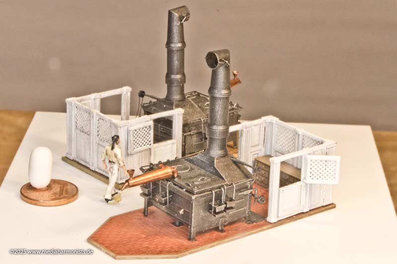
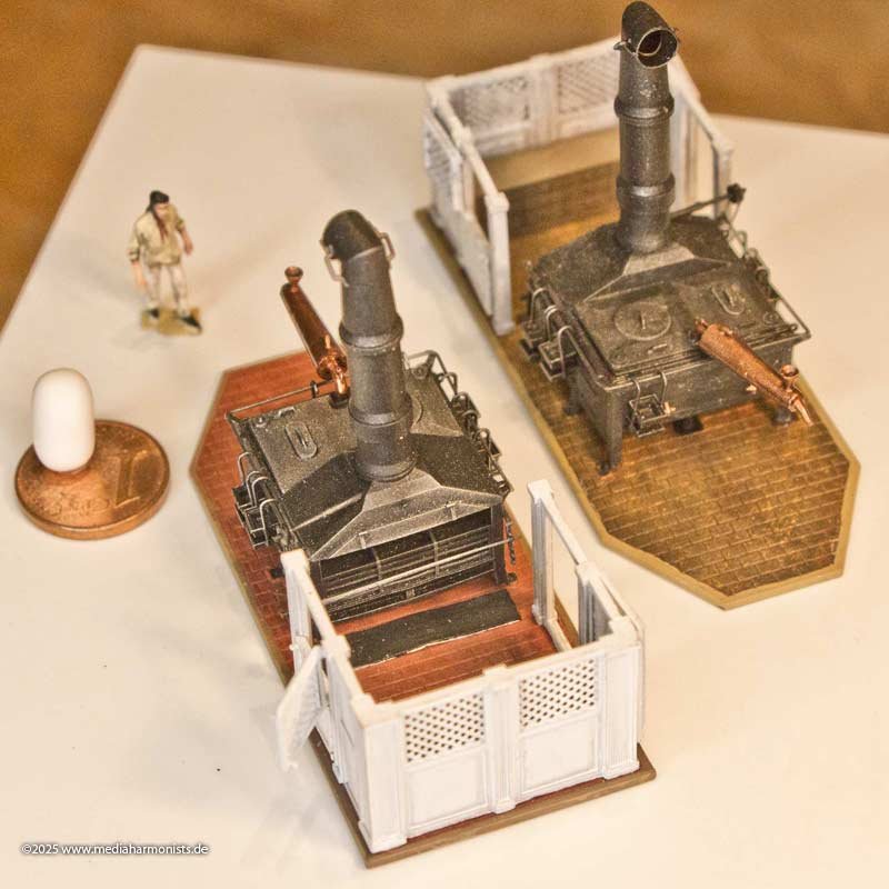
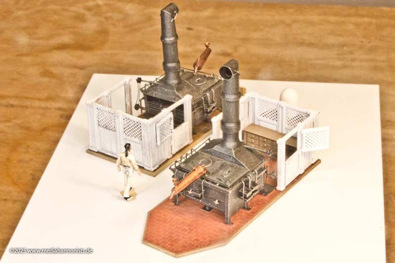
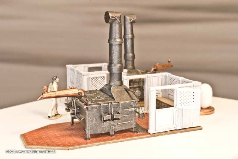
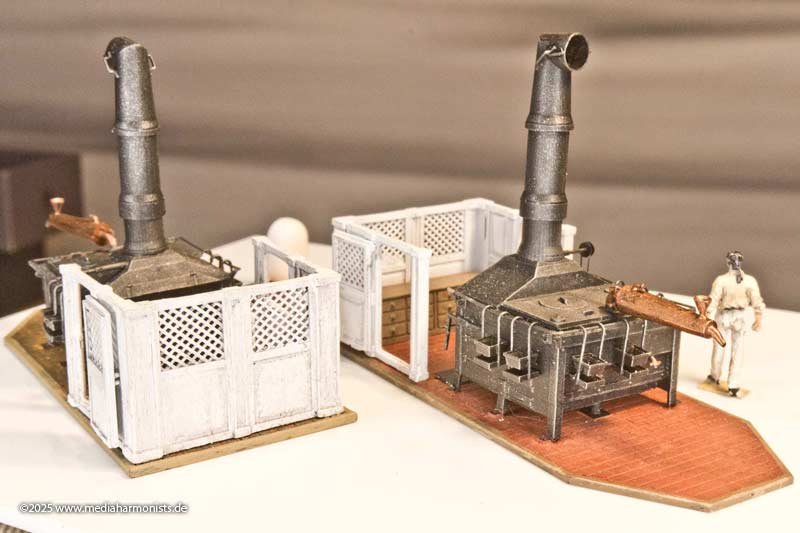
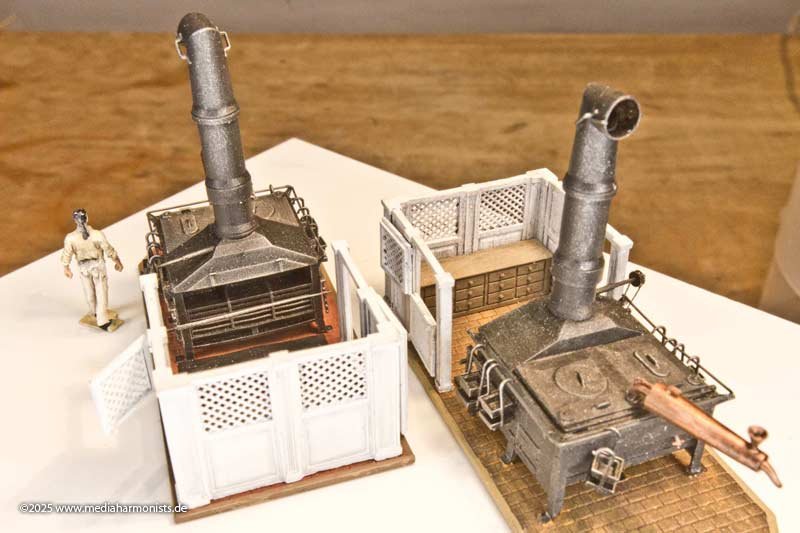
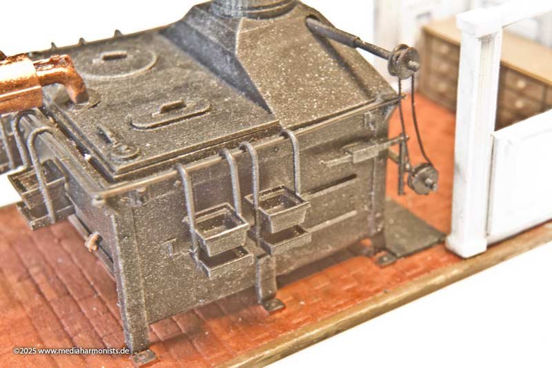
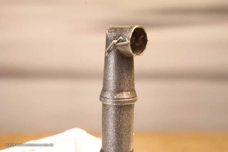
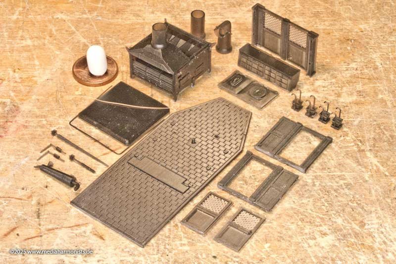
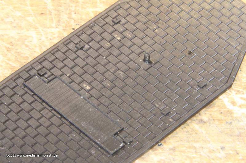
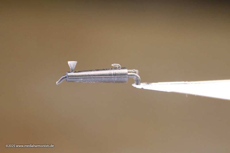
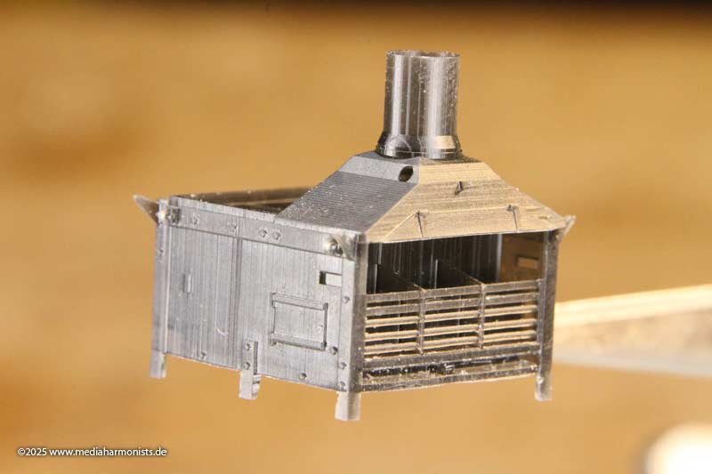
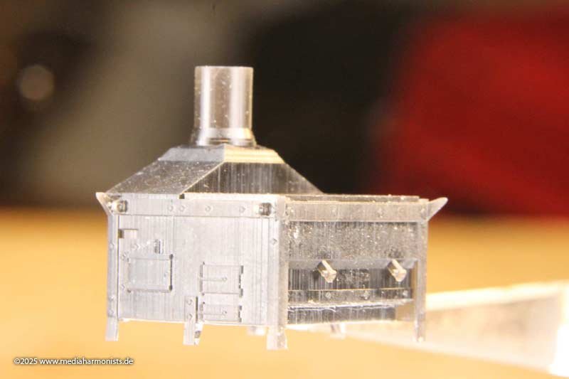
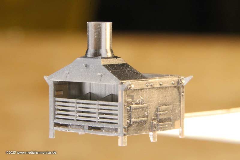
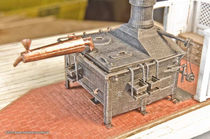
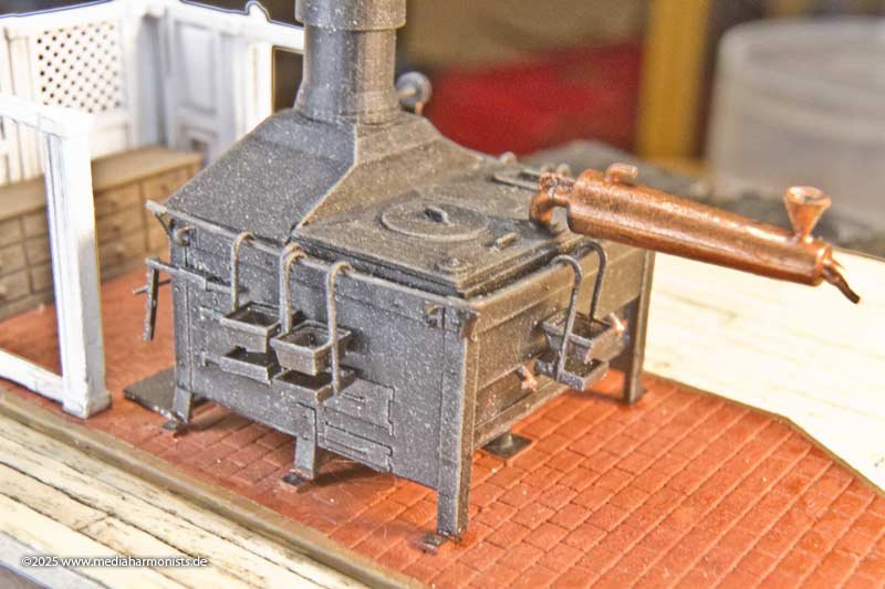
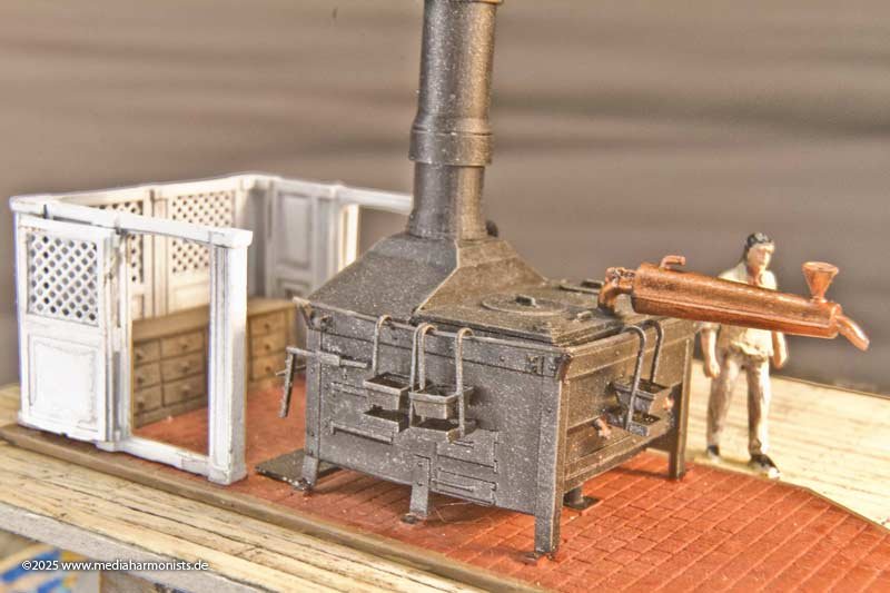
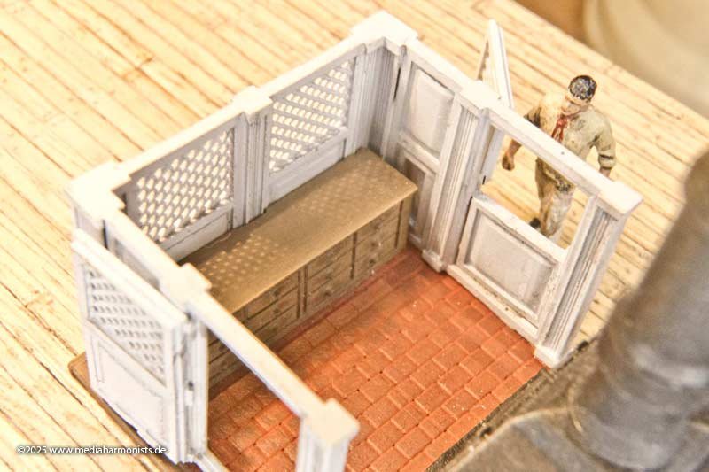
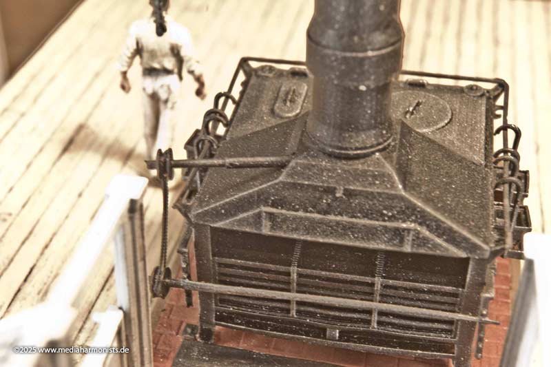
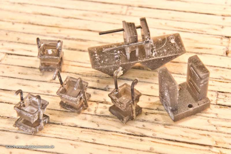
I had finally found the time to finish off a few little things around the stove. It was slowly becoming what I wanted http://www.shipmodels.info/mws_forum/images/smilies/icon_smile.gif Here are two colour versions, one with a classic red brick floor and one with the typical southern English yellow-beige floor covering. And here in the detail shots you can also see the warming trays that could be hung on the handrail of the cooker. Of course, the stove also includes the kitchen area. I have chosen the wickerwork that can be seen on the contemporary model of the Princess Royal and others. The whole thing is a cute little kit of 22 parts. The drive chain is twisted copper wire and the rail is bent wire, for which there is a template. Here are a few more details: The base plate with catch tray and tube for the fresh air supply from the deck below ... ... the stove body ... ... the holders for the skewers ... ... the distiller with all its attachments ... ... ... and the cowl, all that's missing is the round cover plate against rain and storm. As usual, the ensemble was finished with a little diluted ink and a white drybrush, and the metal parts with a little graphite. XXXDAn PS: And it took me a while before I had the courage to print the warming trays directly and completely. But all the attempts to glue the holders on with holders were just horrible in the result ...

-
Diameter of shrouds Heller 1/100 HMS Victory
dafi replied to JEFFRAV's topic in Masting, rigging and sails
That is what I used too 🙂 XXXDAn -
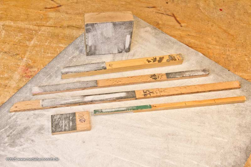
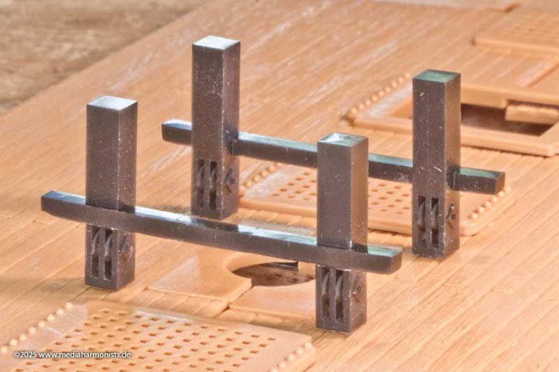
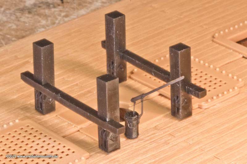
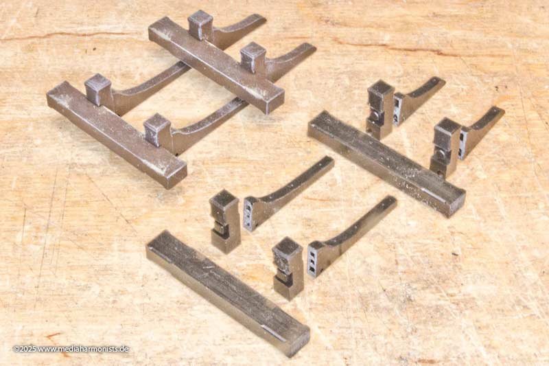
Waiting for Godot ... Since the geometry of the boats is highly complex, the printer has to run at the highest resolution, and that takes time ... That's why I used the time in between to finish a few other things, or rather to give them a final polish. All the bitts on the upper deck have now been joined by the bitts on the upper battery deck, which hold all the halyards of the main mast. Big strong things with nice rollers in the base. Here with the swifel pump in between. You can already admire them in the open heart of my Vic. The matching deck beam supports. Cheaper by the dozen. A bit of drybrushing here too to modulate the shape. Plus the small kit of the riding bitts and what you can be done with it. And I would like to take this opportunity to out myself again: As much as I like and need high-quality tools, but often nothing beats the basics! - A sheet of sandpaper on the table and you can make smooth and even strokes when sanding - Sandpaper stuck to wooden sticks using double-sided tape allows sanding tools to be cut to the exact width of the workpiece using the width of the sticks. Some of the sticks shown here are exactly the width of the gunports of my Constitution. - Right-angled blocks facilitate sanding at a 90° angle. And when the paper is blunt, a new one is put on. And here is the guessing game of what else I have prepared 😉 Best regards, Daniel
-
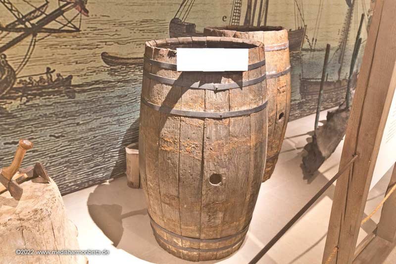
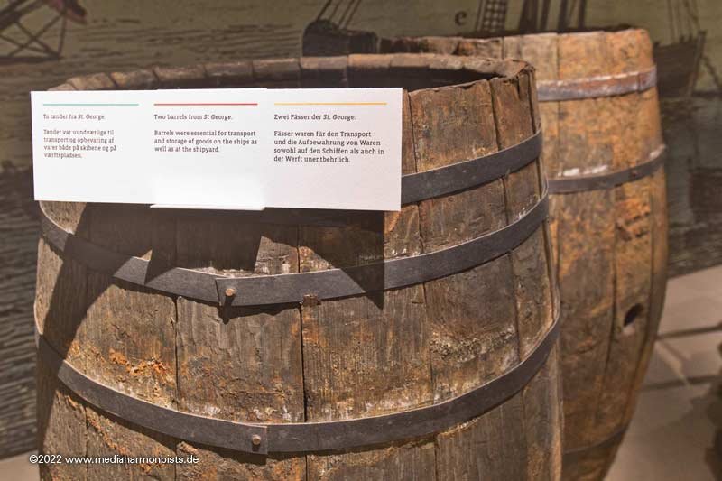
As a wrap-up here 2 casks from St. George wrecked 1812 nearby Thorsminde.
-
Thank you Keith, I always thought I remember all discussiond here, this one slipped my mind. Thank you for redirecting me there. And druxey as always extra thanks, as this is the exact answer I was looking for. And as always the answer is offen nearer than one thinks, in this case exactely 153 cm to the right, seen from the from the center of my working focus up to its place in the book shelf (I measured). Should have grabbed TFFM earlier 🙂 Funny enough, if one resaerches for the leaguer, there are popping up so many measures and not one is equal to the other, most of them much more giving spans of mesures or volume than an exacte size. Anyway the standardization was an important factor, otherwise there would have been chaos in the hold ... XXXDAn
-
For a long time I have been looking for exact information on the sizes and shapes of Royal Navy barrels from around 1800. For the first time, I was able to roughly extract the dimensions of the big water casks directly from a contemporary source: a Leaguer for approx. 150 gallons of water, 4.5 feet long and 3 feet in diameter, easily measured by the scale underneath the keel. To what extent were these barrel sizes standardized, what sizes were exactely used for what purpose and what were the special shapes? Are there any contemporary sources? As my 34 ft launch is about the same size, I could not resist a test. And it really fits surprisingly well 🙂 But as always: questions upon questions ... XXXDAn

-
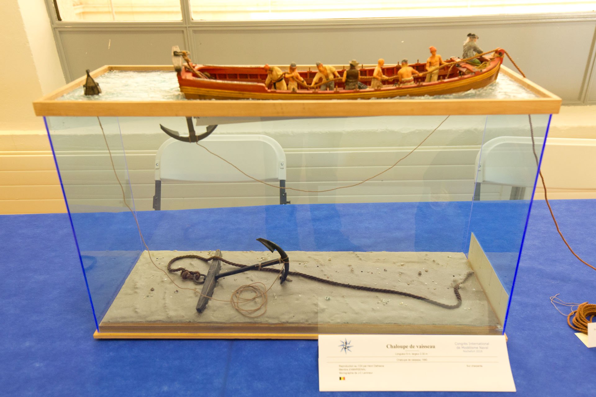
Thank you druxey for the addition, very appreciated! I already realised while building that the way of simply putting a block underneath the stretcher is not sufficiant. I already found ways of fixing the strechers the same way as the thwarts in some plans in contemporary plans in RMG. Also here a modern model I photographed in an exhibition in Rochefort in 2018. Unfortunately I can´t read the name of the maker any more.

-
Pretty cool tool: drilling positioner
dafi replied to CPDDET's topic in Modeling tools and Workshop Equipment
Thank you for the news that it is made metall, I thought by the looks to be plastic ... forth For the scaling of the diameters no problem, use some Scotch film, Tesa Film or masking tape wrapped around to bring it to the next size, should do the trick 🙂 So 3.87 mm becomes a almost neat 4 mm. XXXDAn -
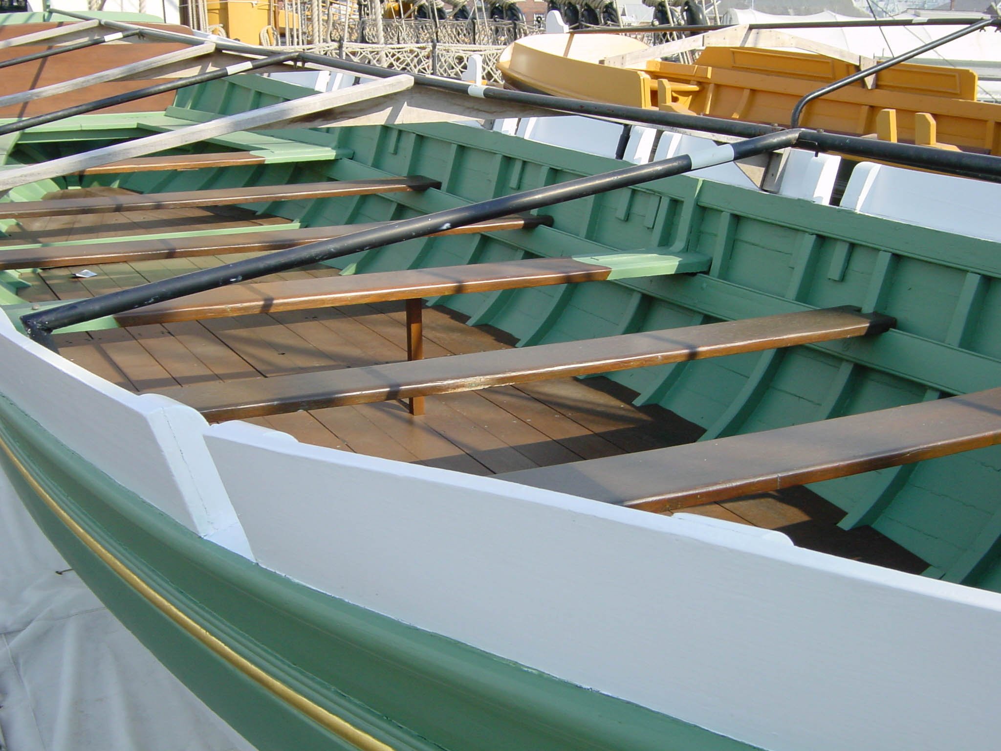
Yes that is a boat of the Vic in P. With an inner deck convenient for todays rower 😉 XXXDAn

-
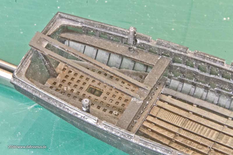
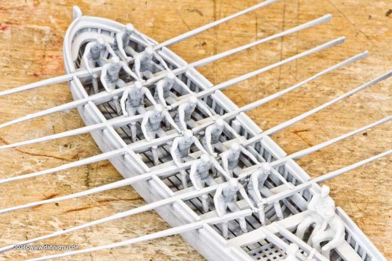
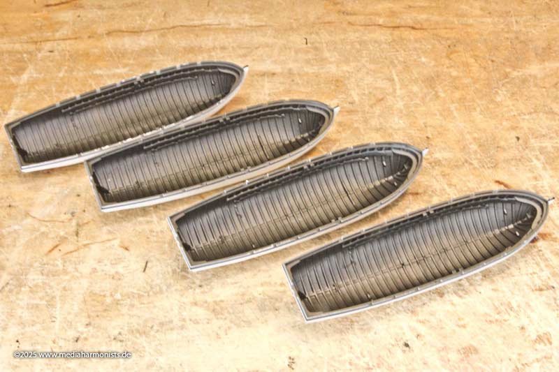
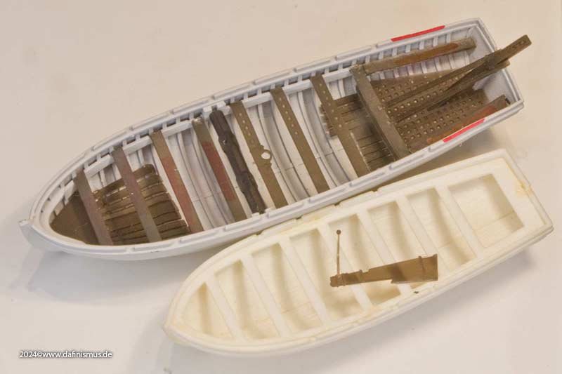
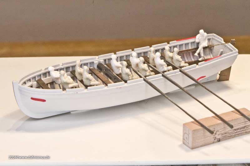
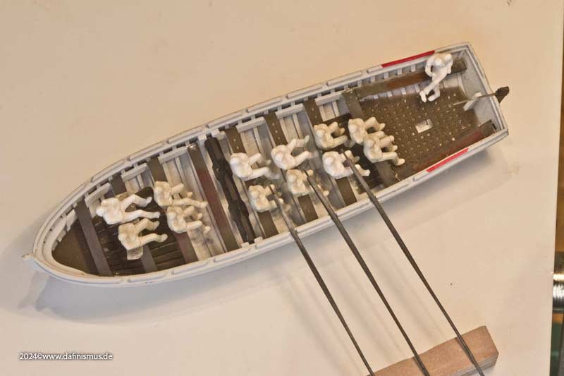
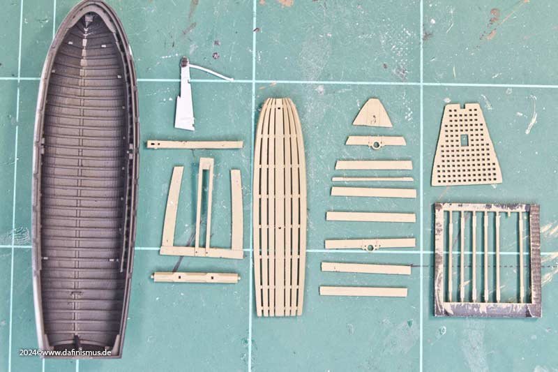
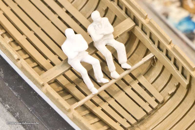
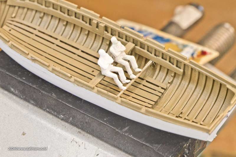
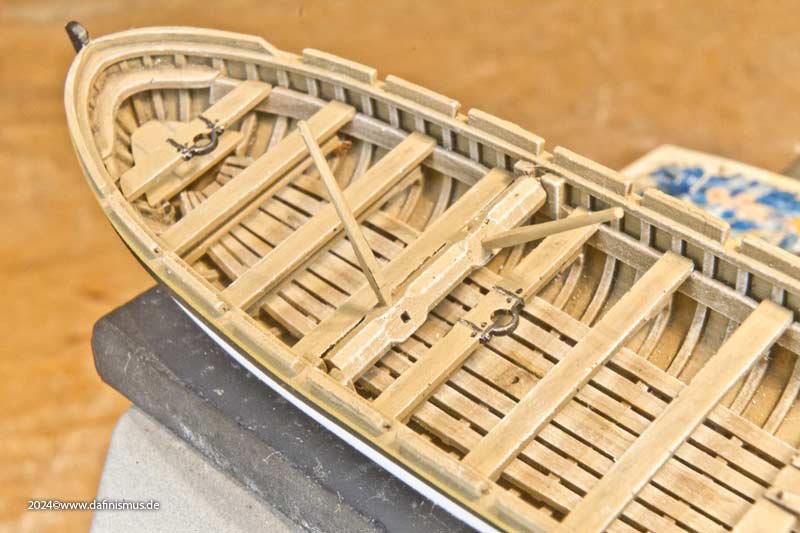
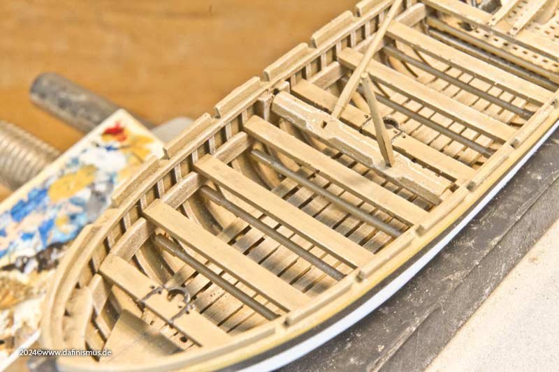
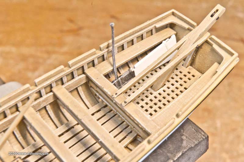
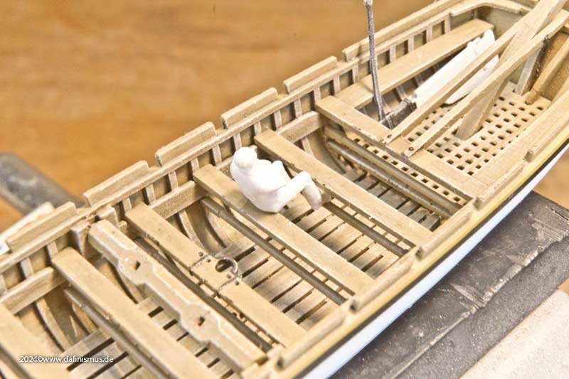
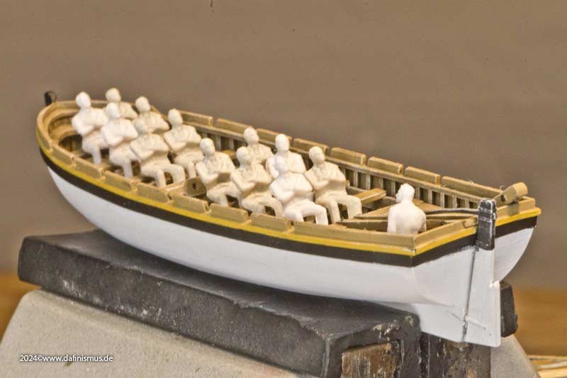
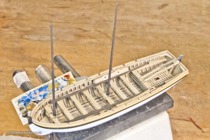
Some time ago, I made the mistake of getting involved with the boats because of the oars. Of course, this was not without consequences ... ... Here is the white “big” launch from the kit and behind it a new “decent” 34 foot launch according to McKay's drawings. Unfortunately, the planks of the inner floor gave way during printing, there was only a small usable remnant at the front and rear. And if you man the boat, you can see straight away that the large boats were rowed “double banked”, i.e. 2 men per thwart and if the capstan is used, one thwart cannot be used. Oar lengths inside and outside and the position to the rower and his arms seem to be correct. But the inside floor still gives me pause for thought. As McKay draws it, it is 30-40 cm too low for the rower's legs and too high so that 50% of the load volume is lost. So it's a strange intermediate height Somehow this still didn't fit. I then rummaged through my documents again and found what I was looking for, as these details are seldom shown. Here is the small kit that has evolved as a result. The inner floor to protect the hull now rests on the frames at the very bottom. The rowers' feet have been given a bar for this purpose. Trial sitting ... ... and it fits reasonably well. With slightly straighter legs it even fits quite well. So the other foot bars are also installed. After that came the thwarts and the other interior ... And again we had a rehearsal sitting ... ... even multiple ones. This also seems to fit. The capstan is removable, so two more rowers could fit in. But the next question is, what was the rigging like? In terms of the mast positions, I would have guessed lugger rigging, which I was able to see live a few times in France, or perhaps sprit rigging, but I'll see what Steel has to say about that later. Above all, all the fittings on the hull are still missing, which are vera often omitted. Greetings, DAniel
-
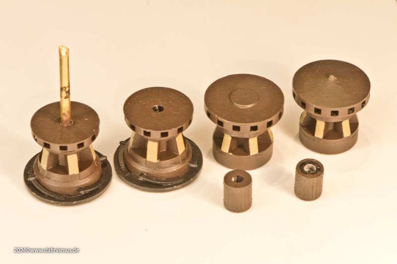
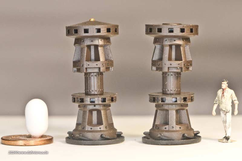
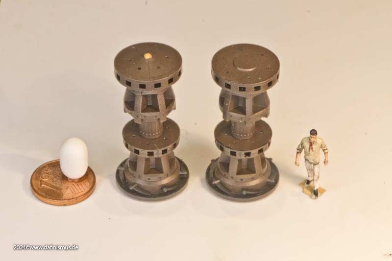
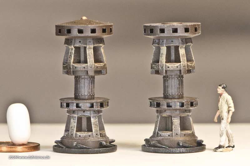
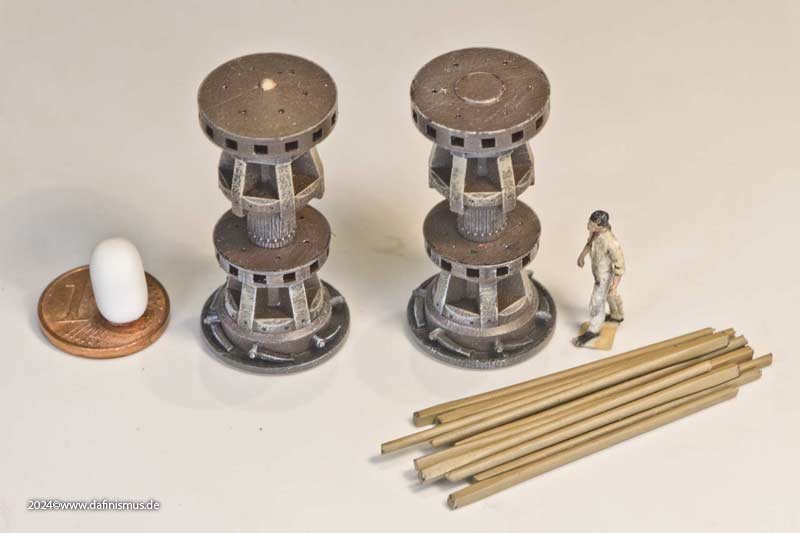
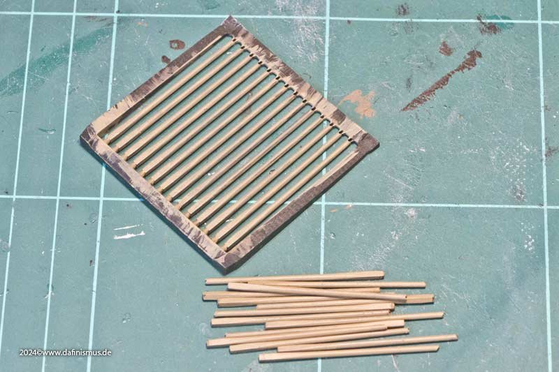
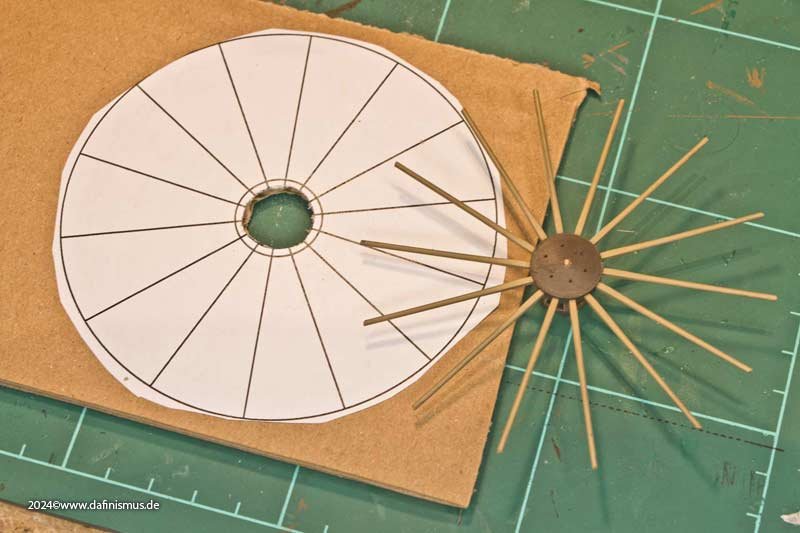
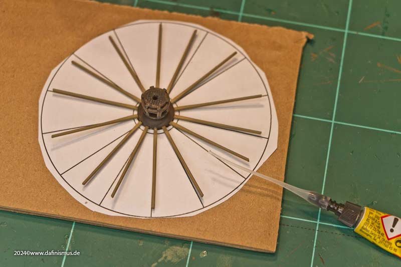
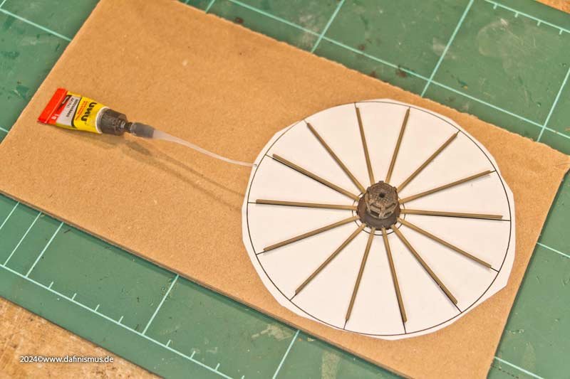
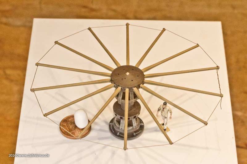
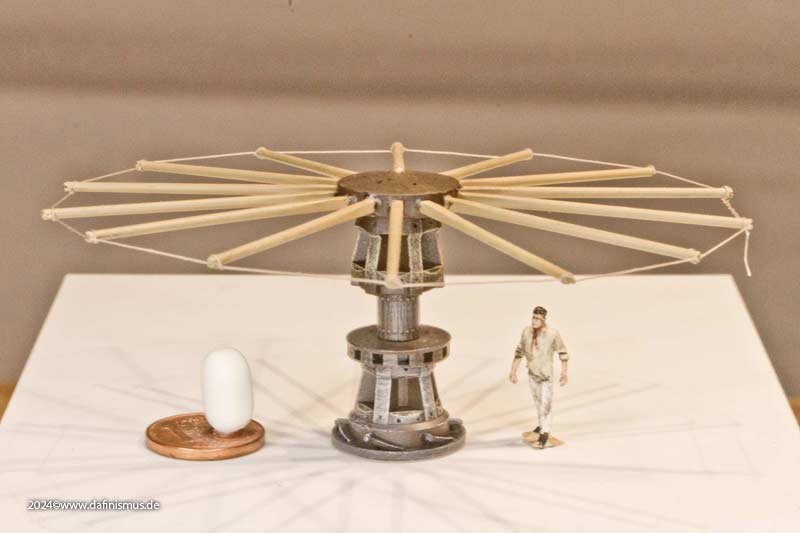
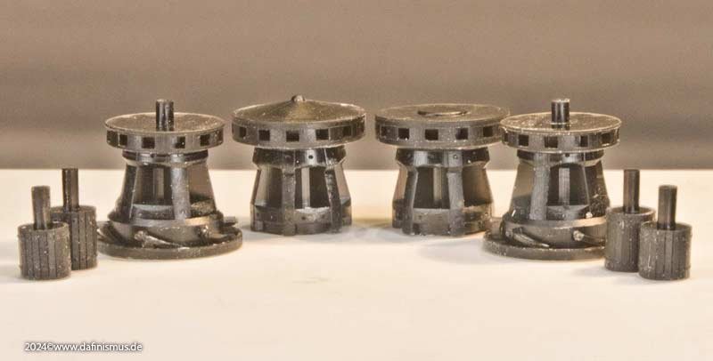
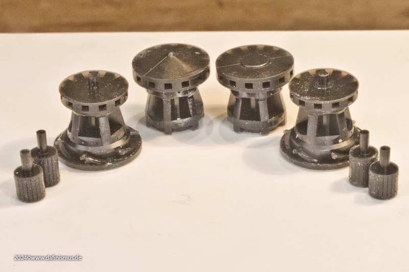
And I was also finally able to finish the capstans. All the parts had been in the making since well into last year, but I never really had the chance to finish them. Basic programming strictly according to plan is always done quickly, but until the look of the printout refreshes my eyes and heart in terms of model making, it takes a few more rounds of printing, tinkering and improving, version #15 is the normal case here. Here is an intermediate version, the brass tubes have now been replaced. Still mising are the bevels on the wedges below the ribs, which allow the rope to slide smoothly from round to pentagonal or hexagonal. I take such pre-prints for color samples, and lo and behold, it looked stupid in this color scheme. Here is already the penultimate version. [Note to self: HOPEFULLY!] Good enough for a prototype. [Note to self: HOPEFULLY!] And what do I always say? Before applying the aging, a clean base coat must be applied. Here you go. And then life gets in: The wood starts to show at all the rubbing points of the rope on the drums. After several tests, I decided on a non-covering drybrush, which gets across most of what I would have liked to show. And someone else has bombed into the picture: The capstan bars ... ... to match the capstan. I made a template for alignment, using corrugated cardboard as a base to sink the upper part of the drum into and bring the spars to paper height ... ... bars inserted into the capstan and the capstan inserted upside down ... ... bars aligned and glued. Then the swifter is pulled in and that's it. And here are the individual parts, the middle piece is available in two heights, depending on how the battery deck is fitted with gratings. XXXDAn
-
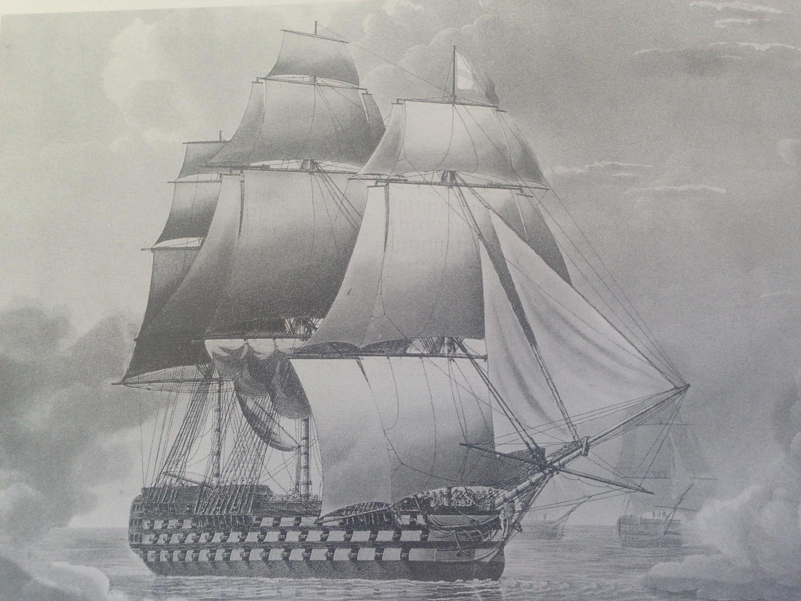
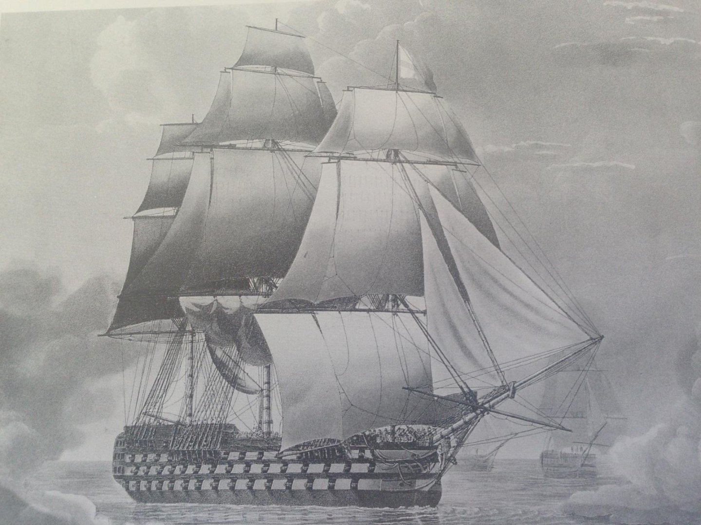
Hello Kevin, at least Butterworth is consistent with his details 😉 Here 2 paintings of his, showing the same stern ... https://commons.wikimedia.org/wiki/File:Thomas_Buttersworth_-_H.M.S._'Victory'_in_full_sail_and_in_a_squall_(1).jpg#/media/File:Thomas_Buttersworth_-_H.M.S._'Victory'_in_full_sail_and_in_a_squall_(2).jpg ... and once the bows, but ... https://commons.wikimedia.org/wiki/File:Thomas_Buttersworth_-_H.M.S._'Victory'_in_full_sail_and_in_a_squall_(1).jpg ... this one reminds me very much on a engraving that Robert Todd did in 1807. And YES it shows the light bands going around the bows, a feature that is documented on other ships of Trafalgar also :-0 So Butterworth is imho a nice addition for getting the feeling and the mood, but not so much for technical details. All the best, Daniel
.jpg.b40e392250b423051cfccedc88c98e9d.jpg)
.jpg.12b4707697bcd9588809b48ee753548e.jpg)
-
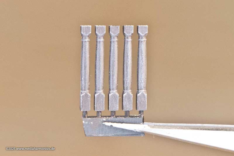
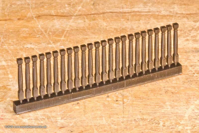
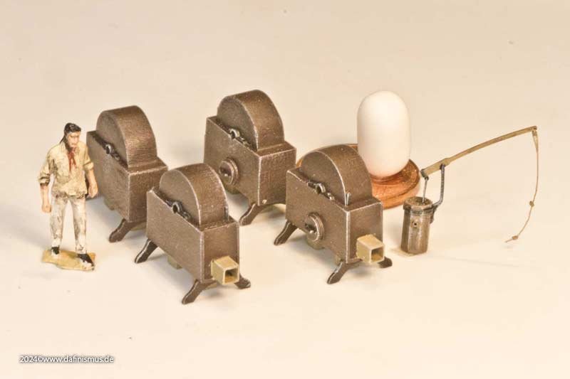
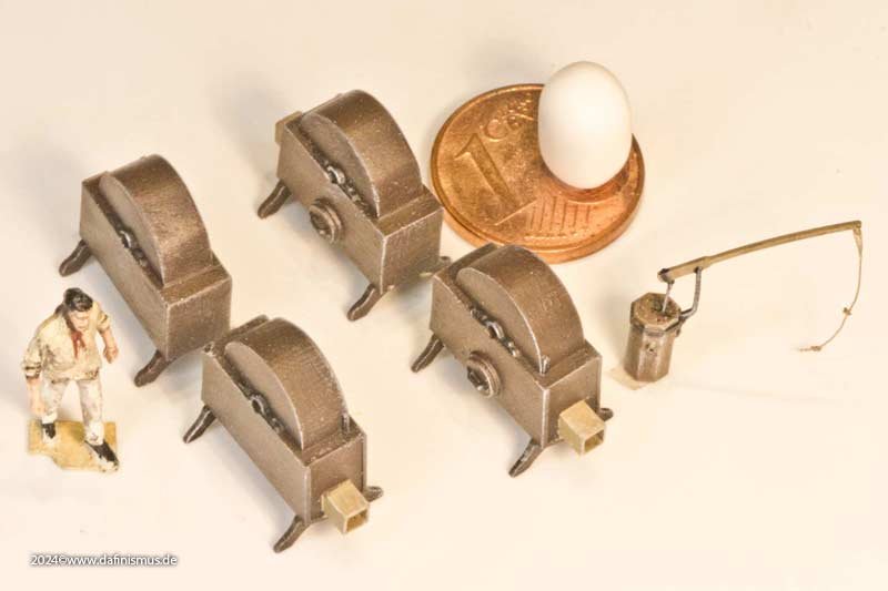
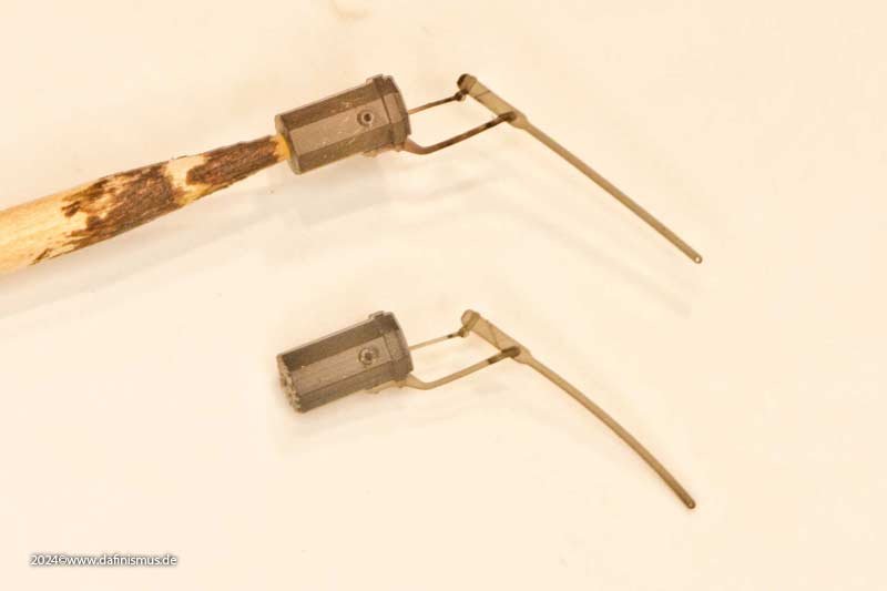
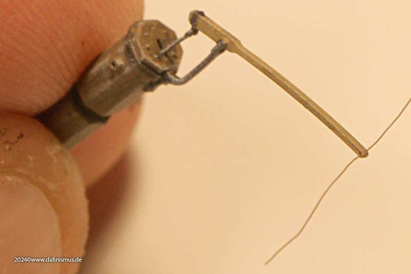
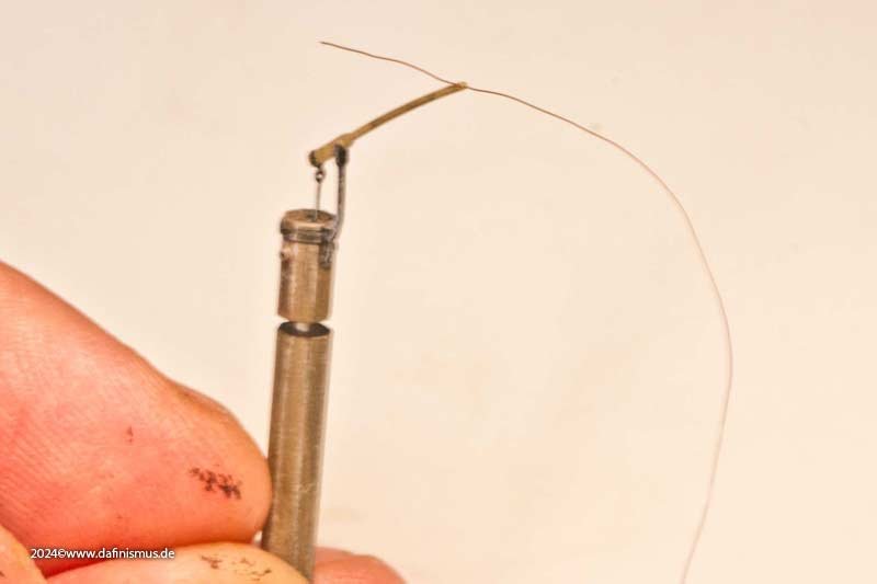
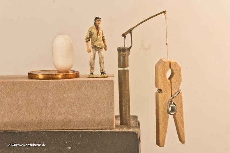
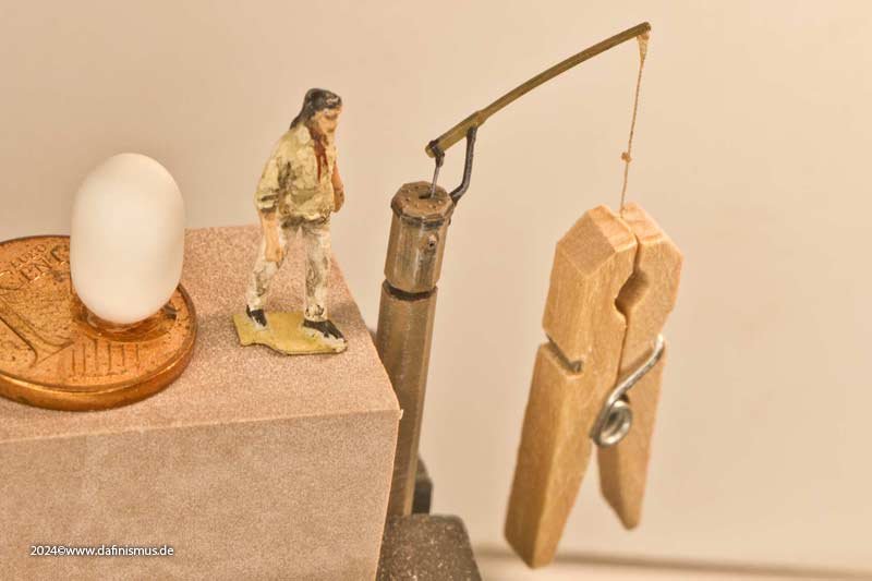
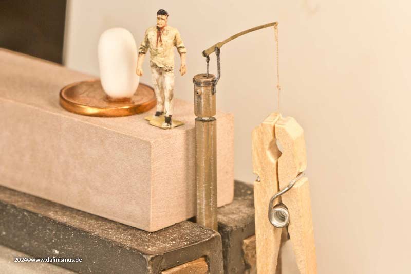
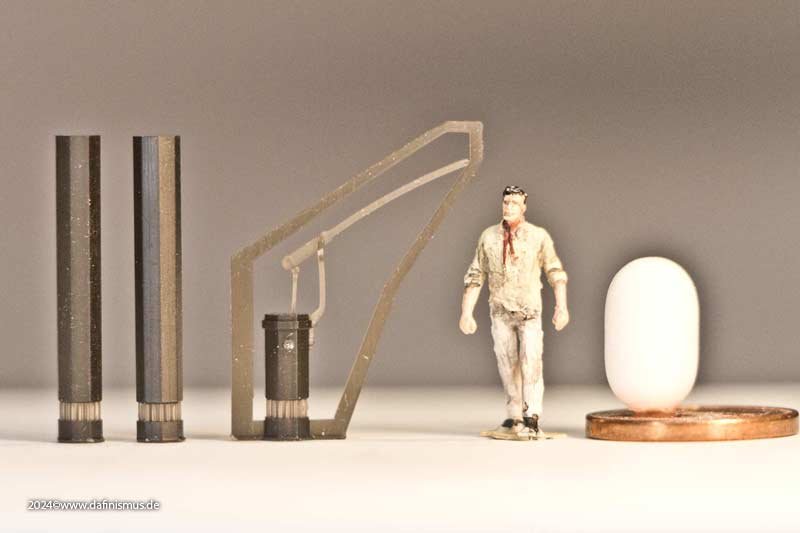
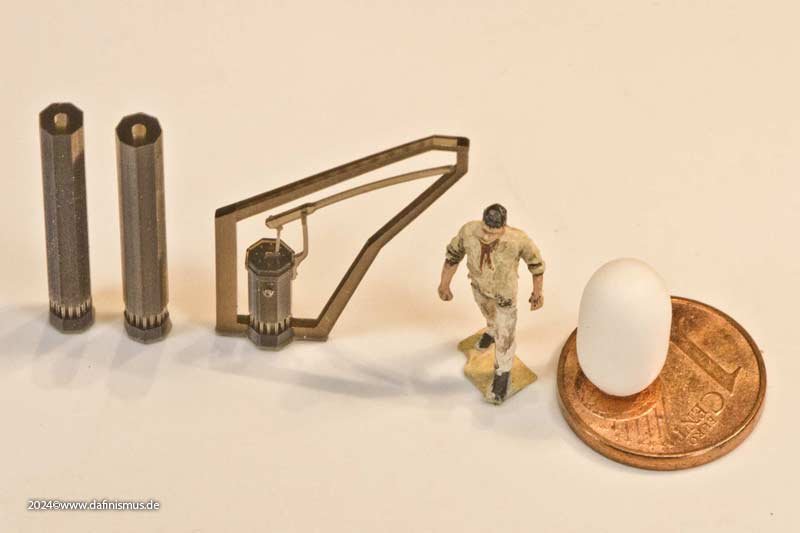
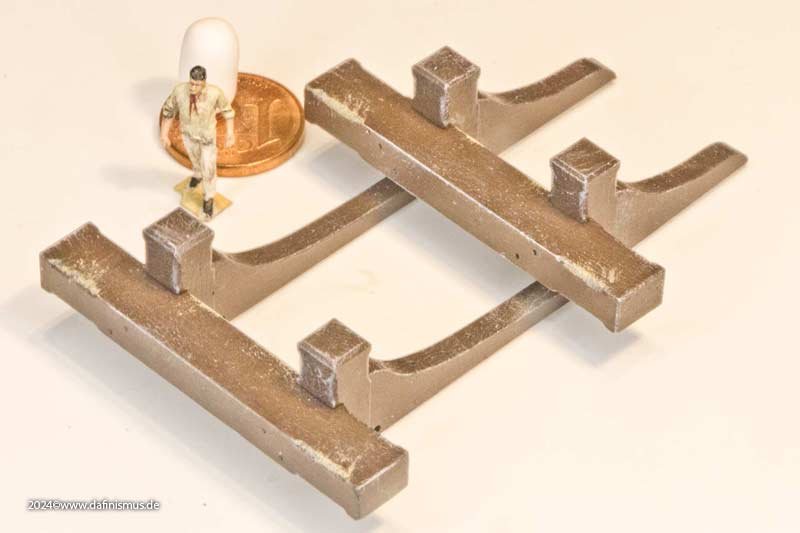
And the pumps were also due. First the elm tree pump. There is a protective bracket to protect the handle and the two through-pipes for the two lower decks are also included. In order not to have a pinch-off point, the handle was printed free-flying, diameter 0.5 mm x 0.5 mm. It came out straight, but when washed in acetone it bent uniformly on all prints. It's better to make a connection at the top for the next print in the hope of minimizing warping during washing. Therefore, a glass of hot water, briefly dipped in ... ... kept in shape while cooling down and - tata ! - everything is straight again 🙂 Here is the comparison picture. So never cold bend resin, it works wonderfully with heat! Then I discovered that I had made a 0.15 mm hole in the 0.5 mm x 0.5 mm handle. Checked the passage with a wire ... ... and pulled in a rope. It actually really worked 🙂 The wooden clamp is not a standard one but a mini clamp ;-) And the chain pumps have also arrived. XXXDAn

-
Oh God, now the building report has actually slipped so far down that archaeological excavations were almost necessary to find it again ... A lot of business in the business, vacation, home garden, garden plot and life itself - lots of things that can get in the way and prevent you from tinkering. But a little something did happen. On request, I did a bit of research into the deck accessories. First the riding bitts. Another small kit in itself of 10 parts. XXXDAn
-
Another pure guess: lightning conductors? to be tossed into the water in thundery times? XXXDAn
-
Hello Tillsbury, here are the dimensions of the mizzen mast as per Heller. XXXDAn
-
Is there any hint or knowledge if the keel was coppered underneath going round th whole keel or if the coppering went "full stop" at the edge of the false keel? XXXDAn
-
Coming back to an older entry in this thread: @AON First line possibly means red arrows 🙂 Blue arrows most possibly is the gap for the anchor davit, as the upmost rail passes through and the bolster underneath is visible. XXXDAn