HOLIDAY DONATION DRIVE - SUPPORT MSW - DO YOUR PART TO KEEP THIS GREAT FORUM GOING! (89 donations so far out of 49,000 members - C'mon guys!)
×


dafi
-
Posts
2,426 -
Joined
-
Last visited
Content Type
Profiles
Forums
Gallery
Events
Everything posted by dafi
-
 The last time she set sails was on 04th December 1812 heading for portsmouth to get her ballast out and the rigg cut down. Last entry on the sea going log was on 18th December 1812. This was still before the introduction of her round bow in 1816. Afterwards she was still moved around a bit in front of Portsmouth but never on her own sails again. The film gives a great introduction on ships of this age and is marvelously done in this regard. As the reconstruction is based on McKay and Bugler, the details shown for this timeframe 1803 to 1805, there are plenty of anachronisms like the vent trucks for the hold (19th century) and the carpenters walk (1816) and many many more. XXXDAn
 -
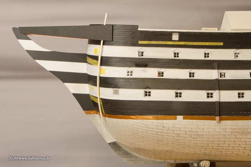
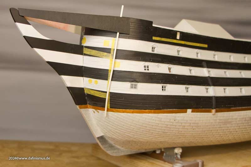
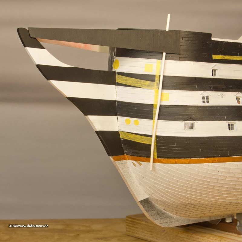
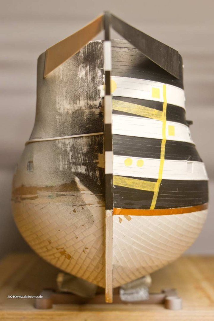
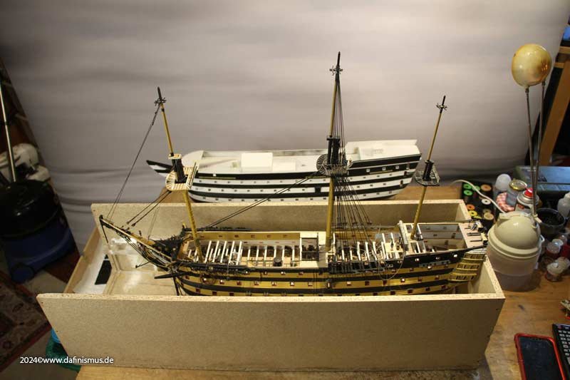
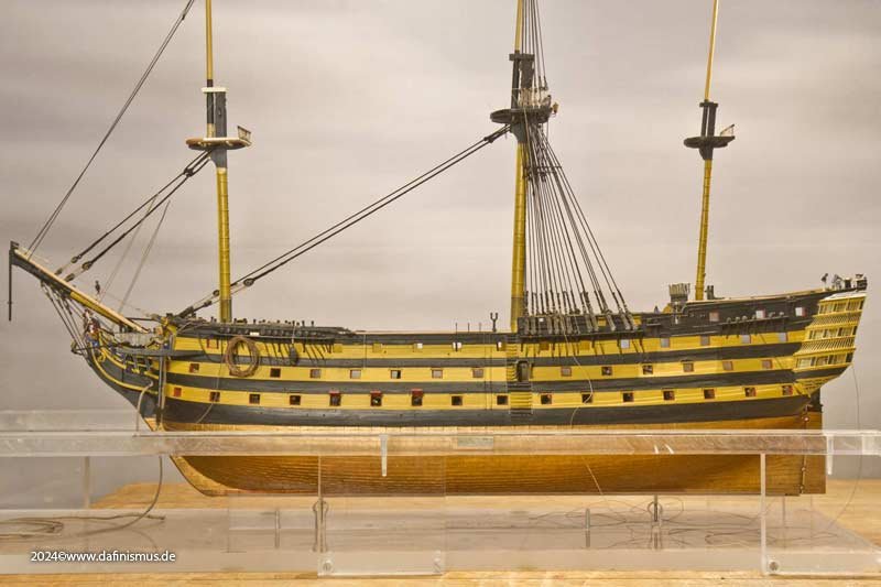
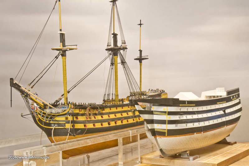
It has now been 4.5 months since the big modeling show in Evian France. Since then, my Sleeping Beauty has been lying in her box in the camper van, as I haven't had the time to kiss and wake her nor the space on the work table to lay her down gently. This weekend I finally pricked up my lips and gave her a really nice wake-up kiss 🙂 And I took the opportunity to take a few beauty shots and compare 1803 and 1910 🙂 Is this now considered to be out of box? I also took the opportunity to take a closer look at the new bow. It was based on the three-deckers built between 1800 and 1805. The bowsprit is now also anchored one deck higher. One side is still a bit rough 😉 Hope you like it! XXXDAn
-
Wunderfully done 🙂 XXXDAn
-
Gun Port Wriggles
dafi replied to catopower's topic in Discussion for a Ship's Deck Furniture, Guns, boats and other Fittings
1765 https://www.rmg.co.uk/collections/objects/rmgc-object-66456 Who´s earlier? 🙂 XXXDA -
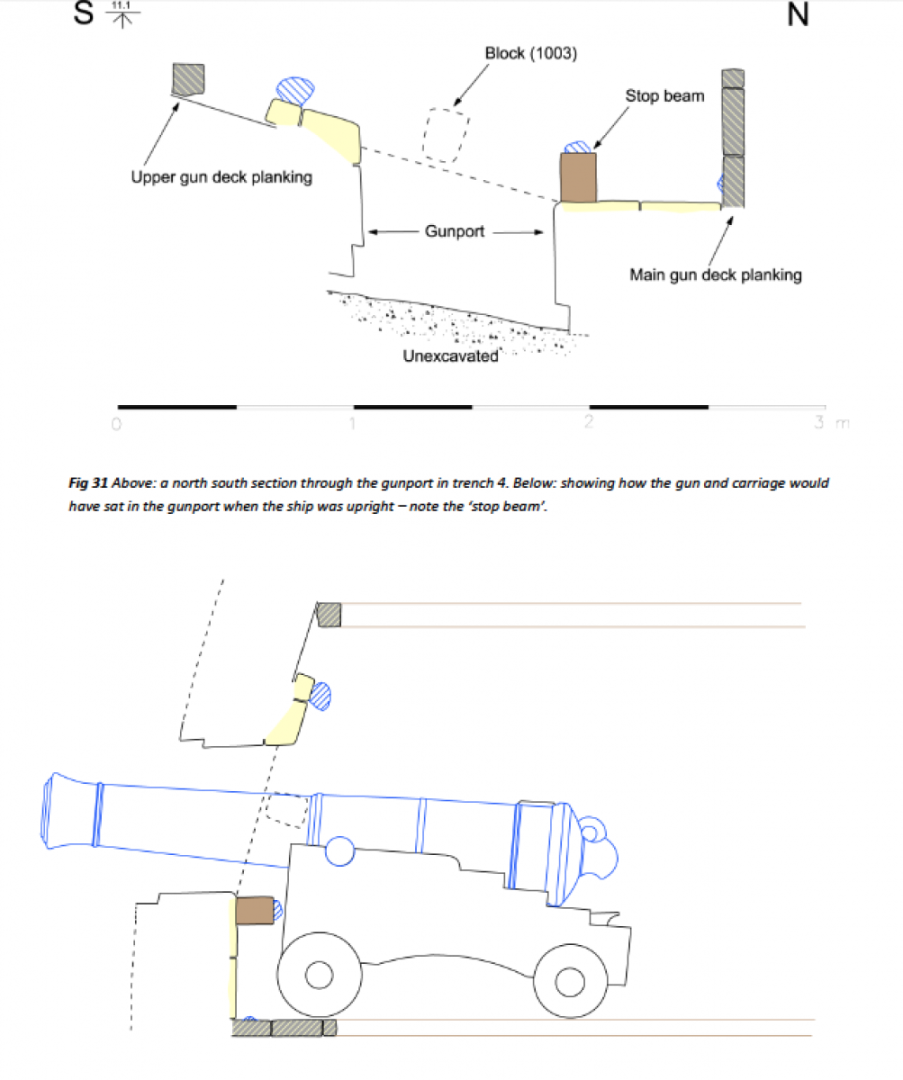
PS: Just noticed after uploading: Also to my previous personal understanding there there should not have been a stop on the upper sill as mentioned above. But it seems Belona´s model shows them. And a quick look at the pictures I took from Vasa shows them too. Too be honest I would expect one there as for sealing the lid off as this area needs some greater tolerance/space as for easy fitting of the hinges, no stop would leave a bigger gap there. The only contemporary source of an actual fitted gunport is the one of Colossus. original Source, not available any more: http://www.cismas.org.uk/downloads.php original Source, not available any more: http://www.cismas.org.uk/docs/Colossus Monitoring and Investigation Report.pdf Page 32 ff especially page 35 The stop beam below the inside of the port is particularly interesting. Attention: Image is upside down. Also interesting is the position of the scupper, which does not seem to follow the rhythm of the ports. There are two parallel ledges on the left and right in the lower area of the gate: possibly to insert a half-height splash guard Above the gate are two things that could possibly indicate the two eyebolts for lashing in marching position. Above the port there is also a worn semi-circular surface against which the guns were braced. XXXDAn


-
The lids were smooth with the planking, but I observed different handling on applications complementing the whales: - Sometimes there was an application applied onto the lid complementing the line of the whale. These ones I suppose were to be nailed-on features and not thicker planking per se as the whales were. - Sometimes the lid cuts a whale without an application, leaving a "gap". I never found the time to research if these two versions were favoured to special eras or if there is a rule/pattern to be seen, to decide whitch one was more probable of a certain ship. Are there any observations/facts known? And another question that often rages on and that fits here nicely: Was there a stop on the lid too? Some older models like the Prince show a stop also on the lid, nailed on as the second layer, also the Vasa has them. But later on this feature is seldom shown in models. The Bellona Modell is one of the few ones. The battle rages as some say, it needs this stop on the lid unconditionally to really make sure that the lid can be closed watertight, as the two profiles join together in a way that a fast "caulking" can be done to seal it off. Others say, it is no problem to seal it watertight even if the stop on the lid is missing, also the fitting of the lid is easier or less danger of that it gets stuck due to warping or the hinges getting worn. Is the any more knowledge about this matter? Was the stop a common feature that was only omitted in most of the models? All the best, DAniel

-
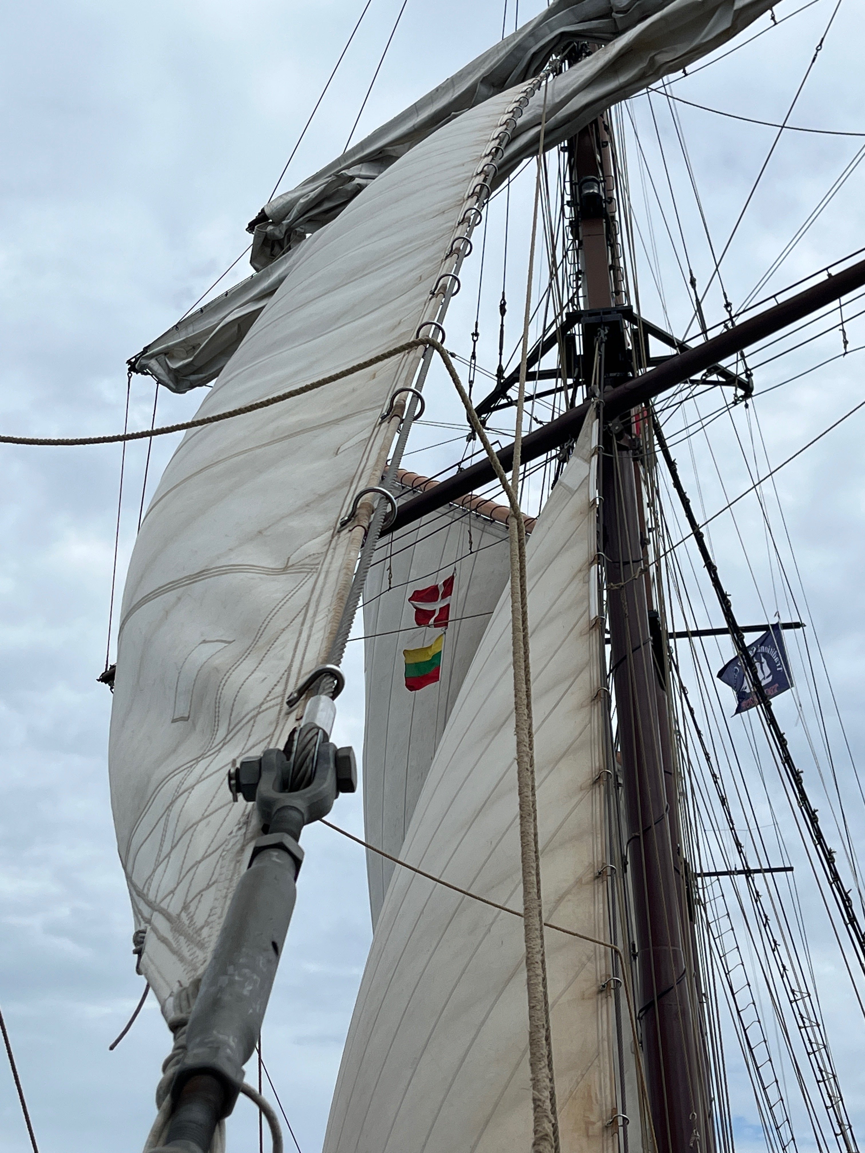
Wonderful thread, thank you! Here for completition a modern version of the horse shoe hank of todays Hendrika Bartelds, with steel cable and screwed hanks. XXXDAn

-
Sweeps and Oars
dafi replied to dafi's topic in Discussion for a Ship's Deck Furniture, Guns, boats and other Fittings
Please also follow the dicussion on the use of oars and sweeps here: Enjoy, XXXDAn -
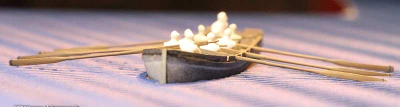
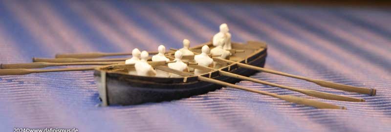
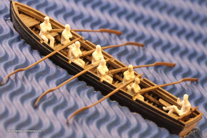
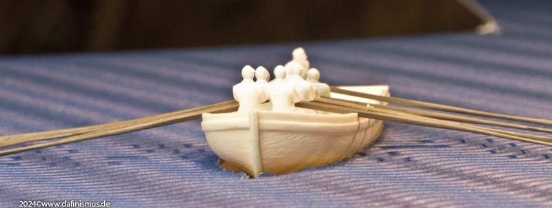
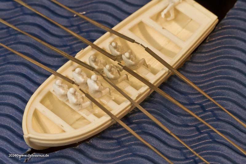
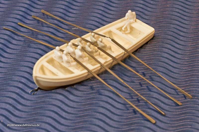
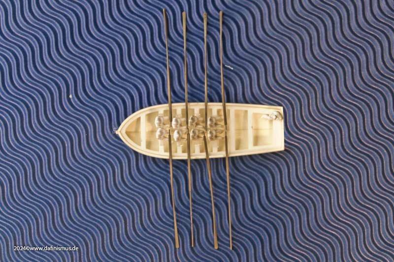
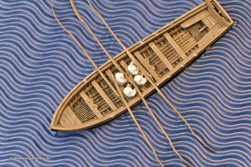
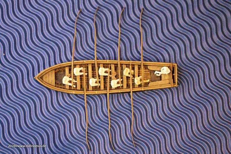
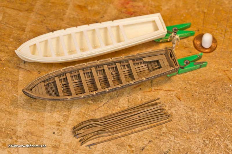
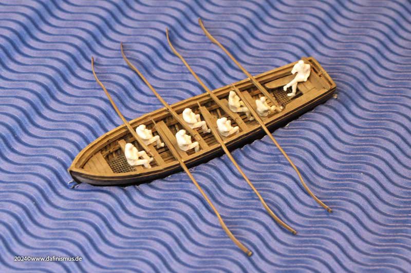
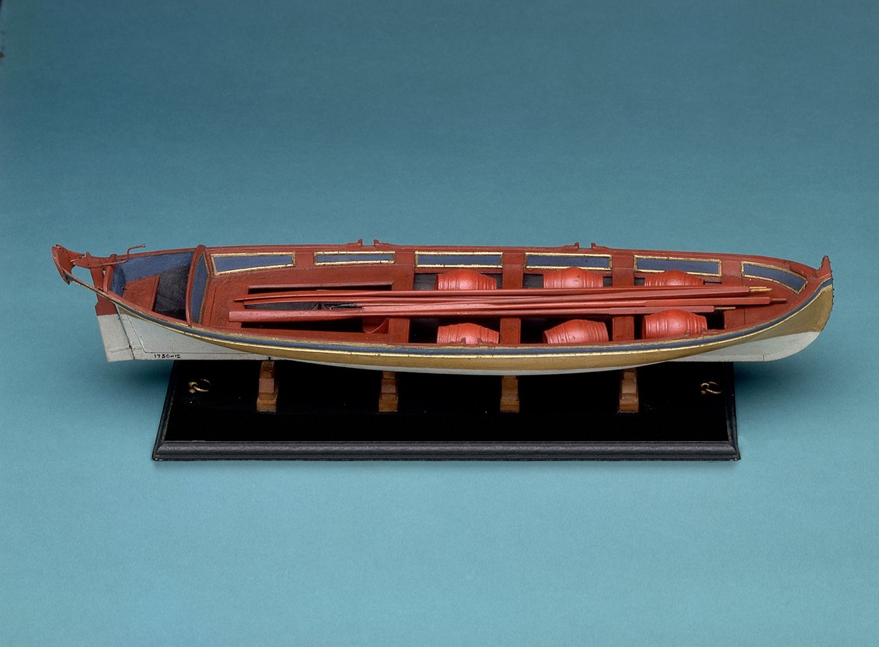
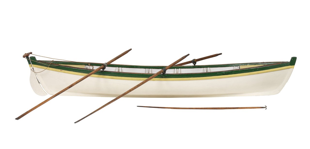
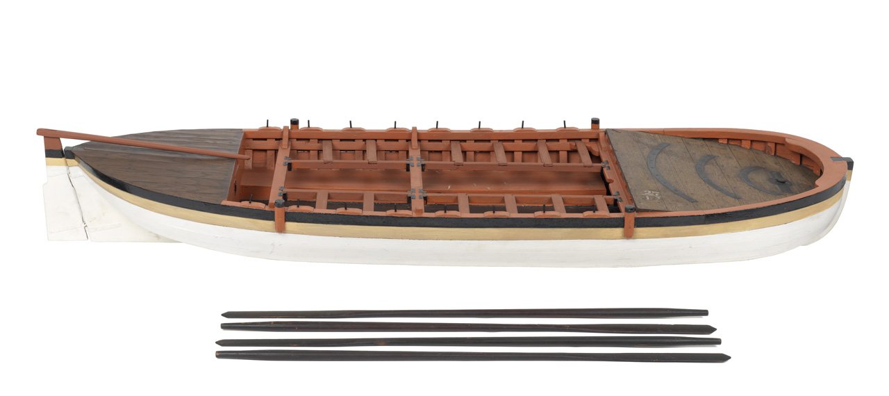
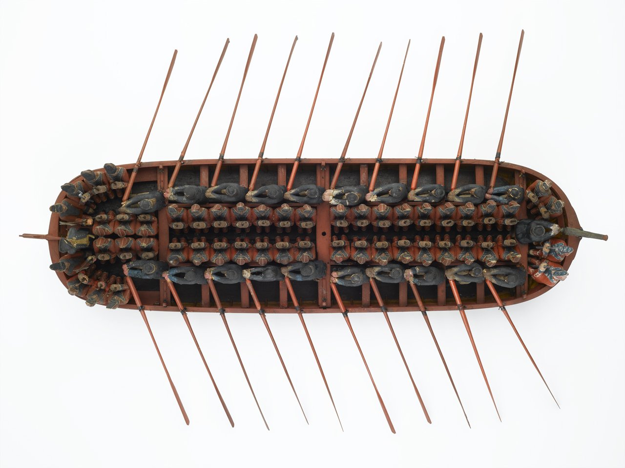
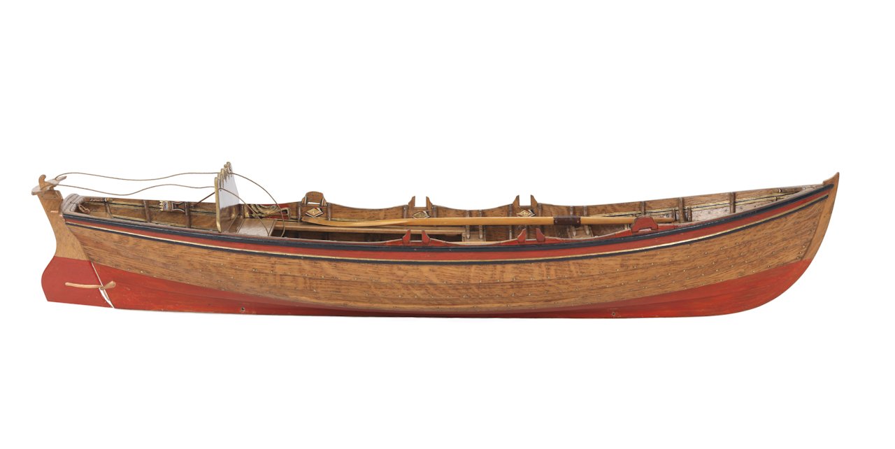
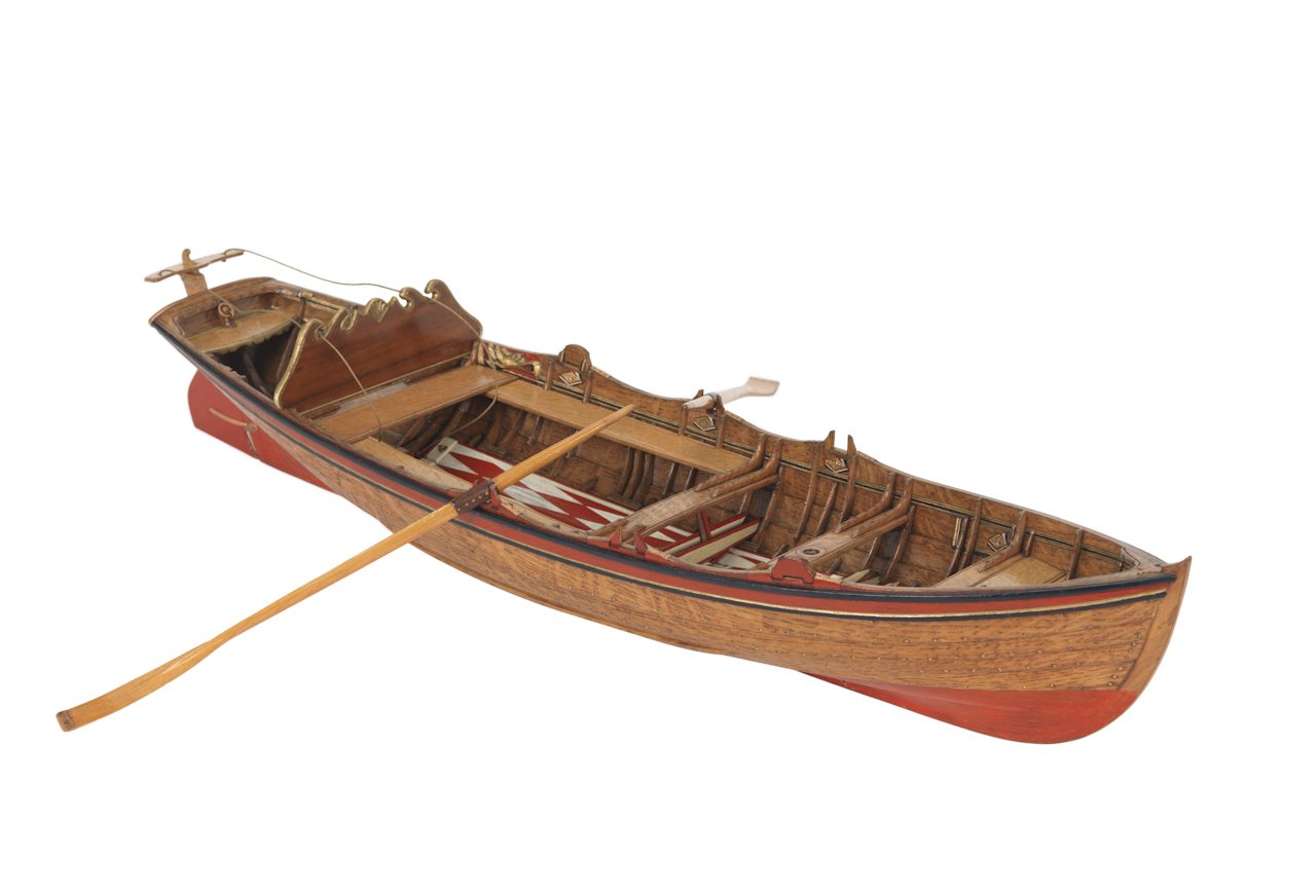
As my quest started with the design of the oars, I was coming from the other direction, but leading my straight to the heart of this topic. Having created oars and sweeps respecting Steel´s data, I was putting them to the test on some of my boats. This lead first to the confimation of the knowledge, that my kit´s versions of boats are not really suitible for the job. Apart from missing all structure and details they also had the thwarts far too high. After reworking the 32 ft pinnace by using only the shell and reconstructing a more true interior it was getting nearer to the real thing. Now I was able to put some crewmen and oars. As a good landlubber I placed immediately two of each on each thwart as suggested by the tholes. But here began my surprise. As Steel indicated: "A leather button is nailed on the foreside, about two inches from the loom, and that edge rounded, to work easily in the rowlock: ..." This lead to the fact, that the oars were far too much in for a double banked use. Basically a crewman should be sitting on the opposite side to be able to grab the handle of his oar, thus crossing the other one. The other fact that can be seen is that in this configuration the crewmen sit far too much on the outside of the boat, resulting in a ridiculus lever for rowing, as already mentioned by Roger in #2. So even if the leather buttom was ignored and the oar taken more out, it would have been a problematic setup. This resulted in the only realistic setup with single banked use and everything looked much more logical. The lengths of the oars fit, the leather button on the right place and a realistic lever for rowing. On the other side I also tried a more broad launch. For these Steel indicated straight sweeps without leather buttom. [note: This is still the original kit´s version, but I think it will do the job this time.] Here we have the space for double banked use. The sweeps do not collide in the middle and the crewmen have enough distance to the rowlock to get a workable lever. This confirmes Allans original quote of Lavery's The Arming and Fitting of English Ships of War where he writes that "in 1783 it was ordered that all launches should be equipped to row double banked." And so I am thankful for the topic here, as it was filling the gaps of my puzzle and giving the right contemporary sources to finish it off. This means with my single banked 32ft pinnace from the first pictures I will fill every second thole, alternating on each side. Also the originally intended number supplied of oars (as for double banked and seen in the first pict) for this boat can be halved. Another question concernes the uneven number of oars on each side, in my 32ft pinnace 4 versus 3. Was this in use as for the uneven propulsion or was the bow place then left free? On the other side in the models of RMG there are many boats with a uneven number of tholes regarding the boat´s sides. As someone once called it "experimental archeology in miniature" 😉 I hope it supports or even confirms all the informations to be found in the previous posts. XXXDAn PS: Had a fast Photoshop and eliminated the supernumerary tholes. This gives a nice detail in between single and double banked boats even in stowed position. 🙂

-
Wonderful, once I saw this info I already found plenty of otherwise very true models showing this "feature" 🙂 But I would expect an even number of twarts for single banked, but there is quite often an uneven number. Does this mean the lesser side had to pull harder or was there one thole left free? Also there seems no rule as to what side of the boat has the most foreward thole. XXXDAn
-
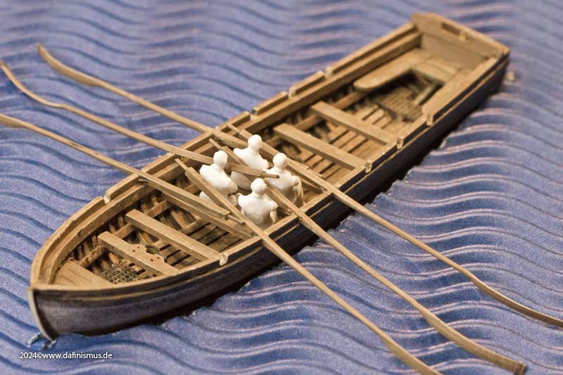
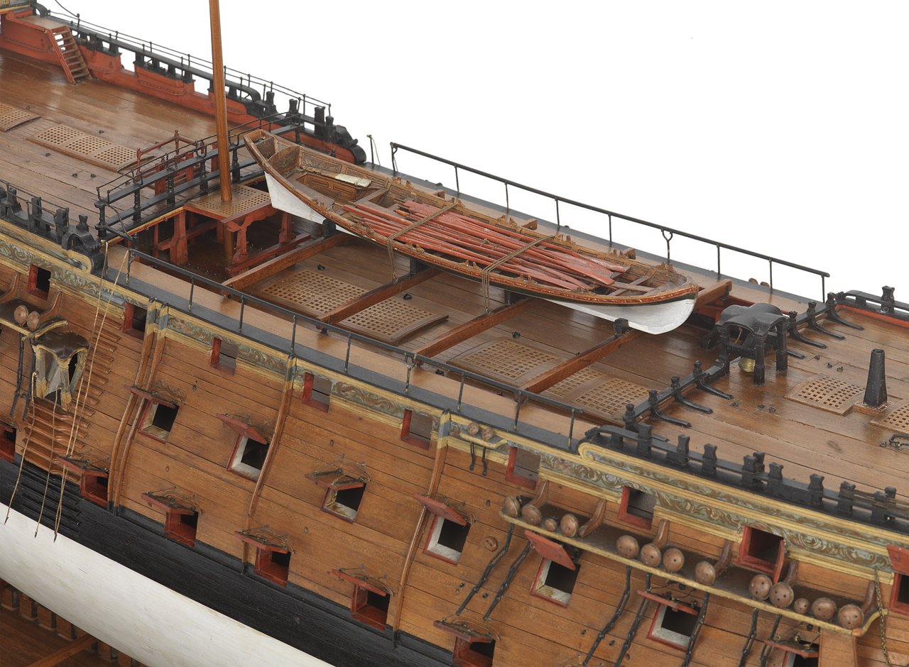
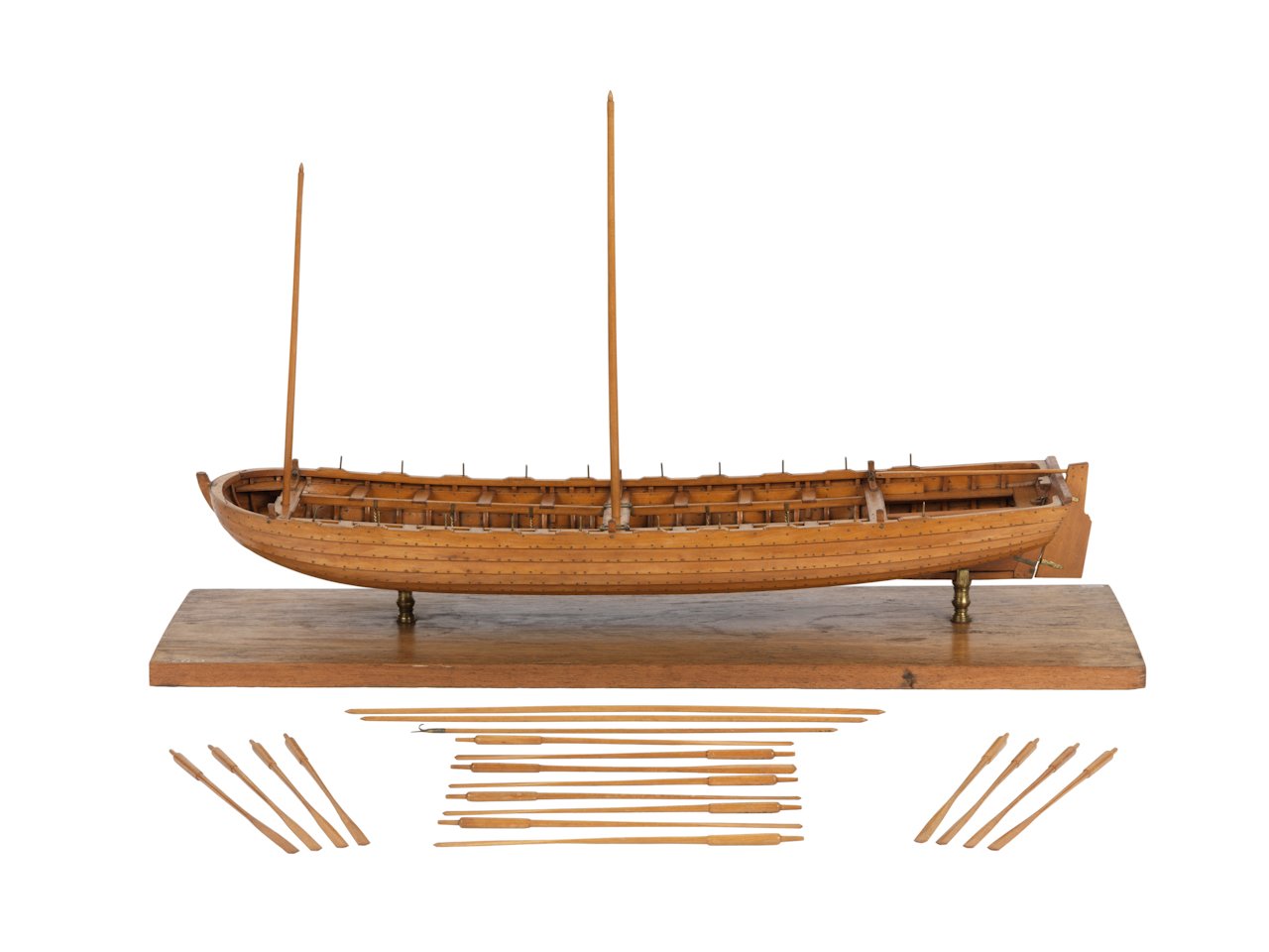
Thank you bringing up this topic again, as I am at the moment working on that. After working on the sweeps and oars, the question was arising, as the oars prooved too long for double banked use. This thread nicely shows the solution as mostely single banked were used was for the "slimmer" boats. Nicely to be seen for my 1800 subject in the 1765 model of victory. I have the feeling too, that for single banked use oars with a curved blade were used, while for double banked use sweeps with a straight blade were preferred. At least the choice of RMG suggests this. Some more hints from the RMG, sorry I did loose the reference numbers on those ones. alternating single banked with oars double banked with sweeps: Special both versions? perhaps single bancked for 4 oars or alternatively 2 pairs of sculls?
-
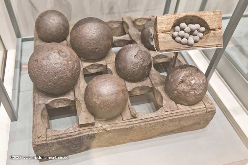
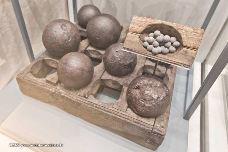
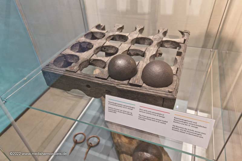
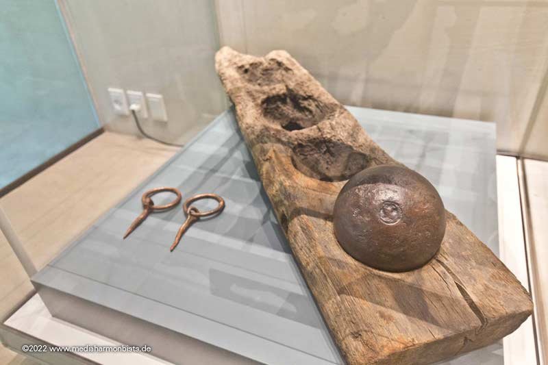
This is how the british stored their extra shot as found in the wrecks at Thorsminde from 1811. XXXDAn
-
Sweeps and Oars
dafi replied to dafi's topic in Discussion for a Ship's Deck Furniture, Guns, boats and other Fittings
That was my first thought too. But I think that is a theoretical value. First the big ships of the line did not have sweeping ports and on top I believe towing with the small boats was much more effective. Or is there any contemporary source showing the use of sweeps on this type of ship? In the meantime I got my print of that volume of Steel´s work and it has much additional information not shown in his other books. The print quality and the drawings in this hard copy are of a much better quality than another volume in paparback I got some 10 years ago. Only flaw ist that the plans and tables are spread over 2 pages, mostely even not opposite pages but on the flip page ... Still puzzeling around the "A leather button is nailed on the foreside, about two inches from the loom and that edge rounded, to work easily in the rowlock" ,the small triangular bit to be seen in the graphics. If applied correctly that means a big overlap in the middle in my examples. XXXDAn -
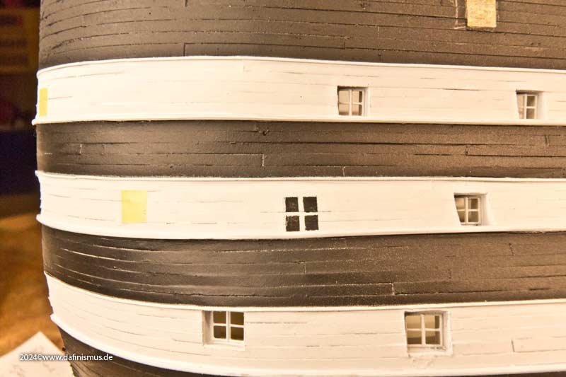
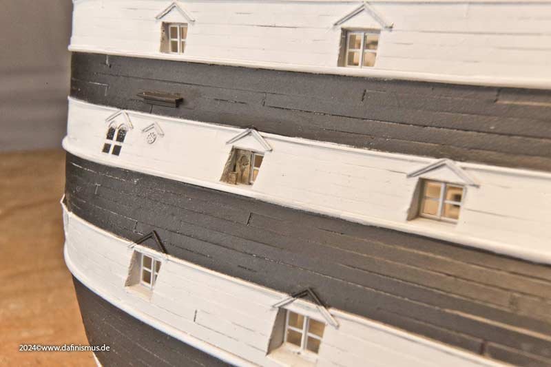
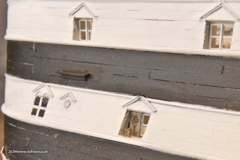
Bad luck for me, thank you eagle eye! But there is much more that won´t fit as already the ports have another rhythm. Just see the port o the lower battery and the one on the upper battery: differently aligned ... XXXDAn
-
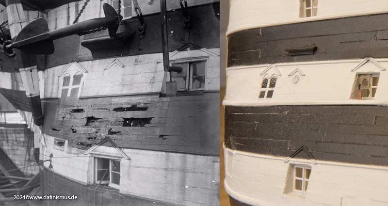
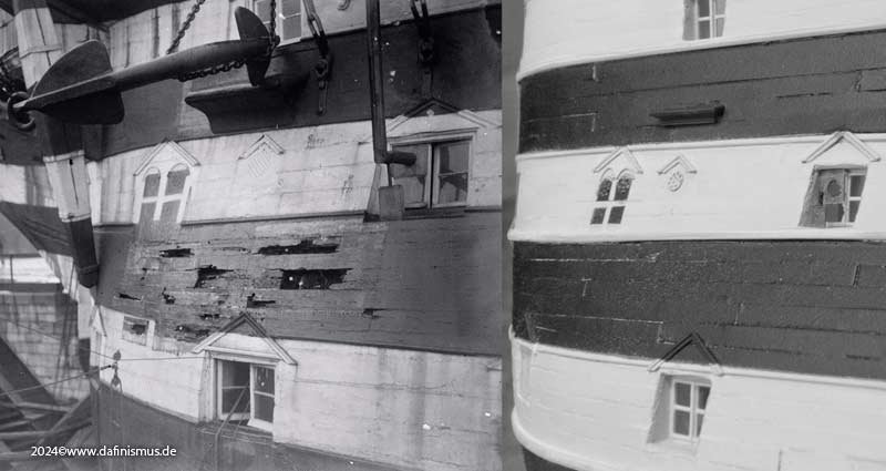
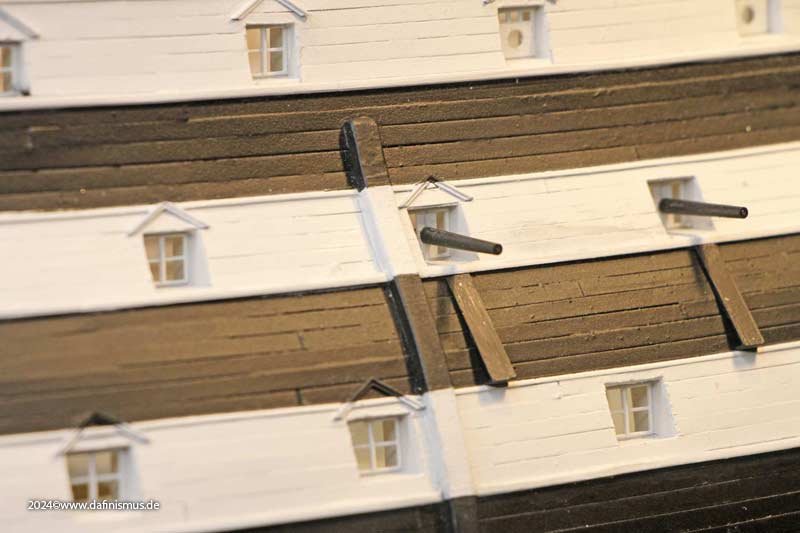
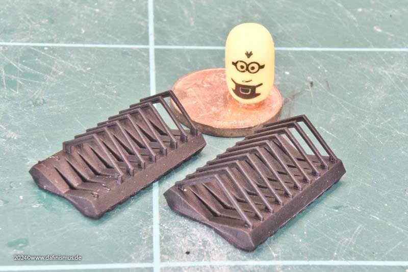
Thank you Druxey, but that is part of the game 🙂 Just realized that I missed one entry, here it is: I went over the stovepipe outlet cover plate underneath the fore chains. First it was reduced in size according to the source. On closer inspection of the photograph, I noticed that the support block could also be a brick. Since the entire shipyard is made of red brick, I took the opportunity to add a bit of color. Here is my comparison picture again. The shoe for the anchor is still far too small, but the rest is slowly coming along :-) Even more distinct without color. As the picture is from 1920 and the state I am showing is 10 years earlier I do not know yet how much of the rot I will show. XXXDAn
-
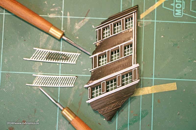
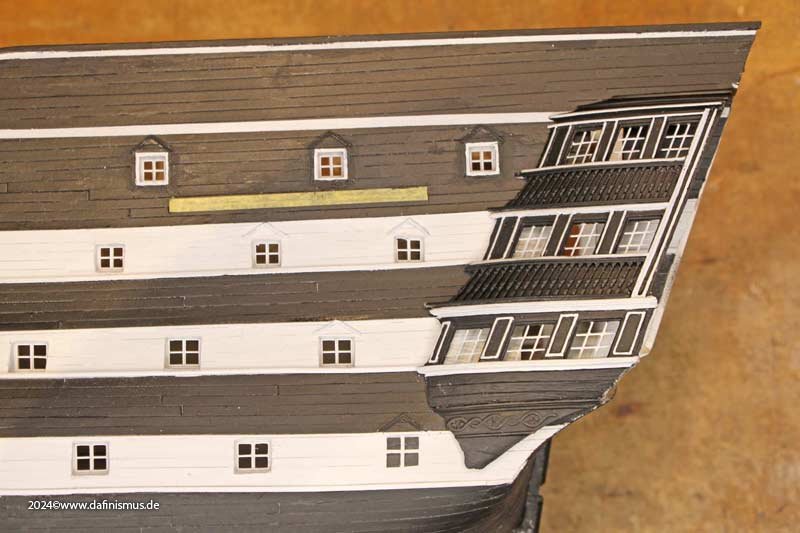
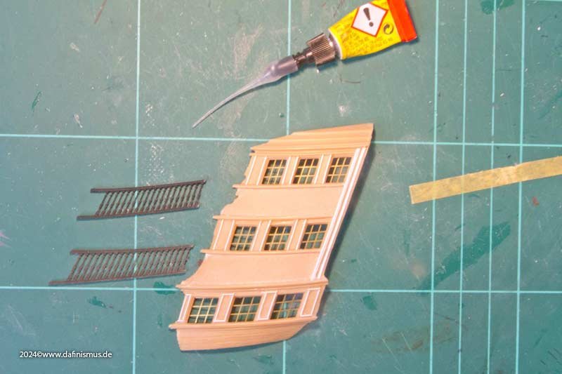
Sorry Druxey if I gave you a sleepless night 😇 When the side gallery was in place, it didn't seem gloomy enough. An anxious look, and sure enough, the white balusters that I had been looking forward to so much just weren't there. Crap. And painting over it looked like crap. I'm sorry, but it did. Like dafi does what dafi does best: Destruction! So I broke out the white balusters and put in new black ones. Now the eyeliner is still missing in the broad white profiles and then it could work. It's only an approximation anyway, as otherwise the side galleries would have to be completely rebuilt. At that time, the curves were less pronounced and the whole structure was more angular. But I can't reconstruct it much better with the documents I have so far. Maybe later on, new sources might turn up. And since I was just tinkering around, I added the chutes for the signal cannons. Probably so that powder and cartridge residues don't stick to the ship's side. XXXDAn
-
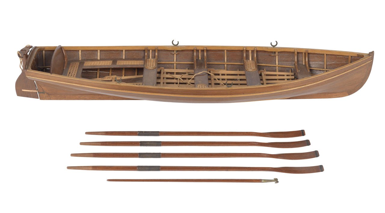
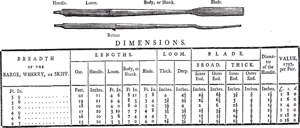
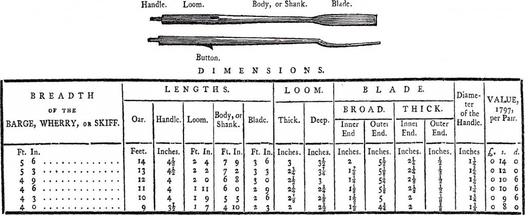
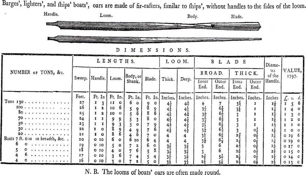
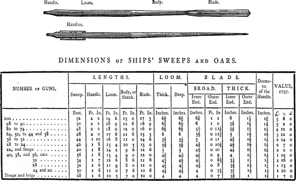
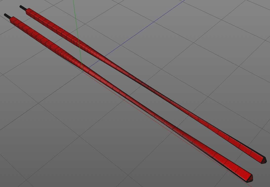
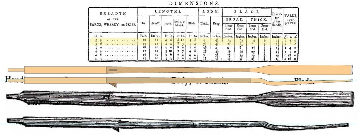
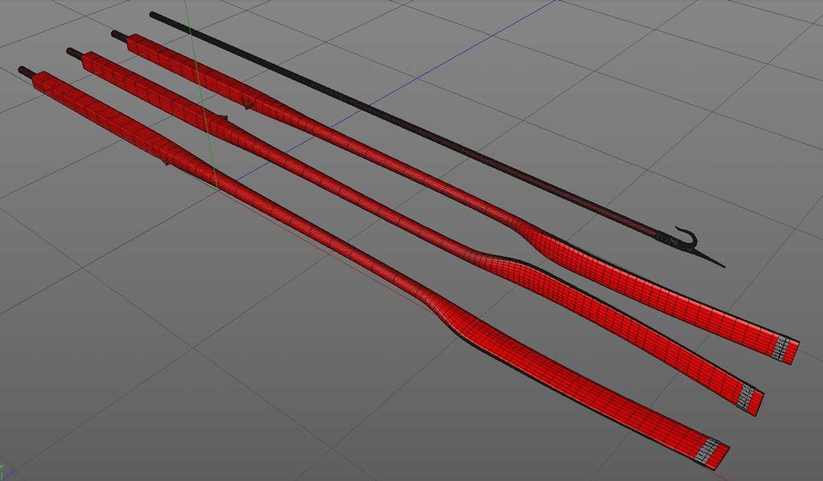
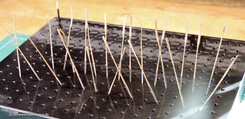
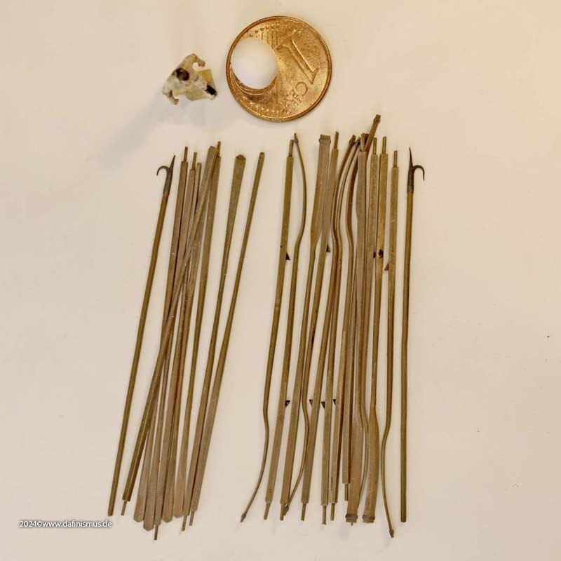
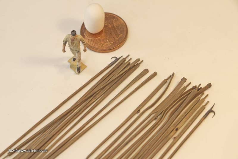
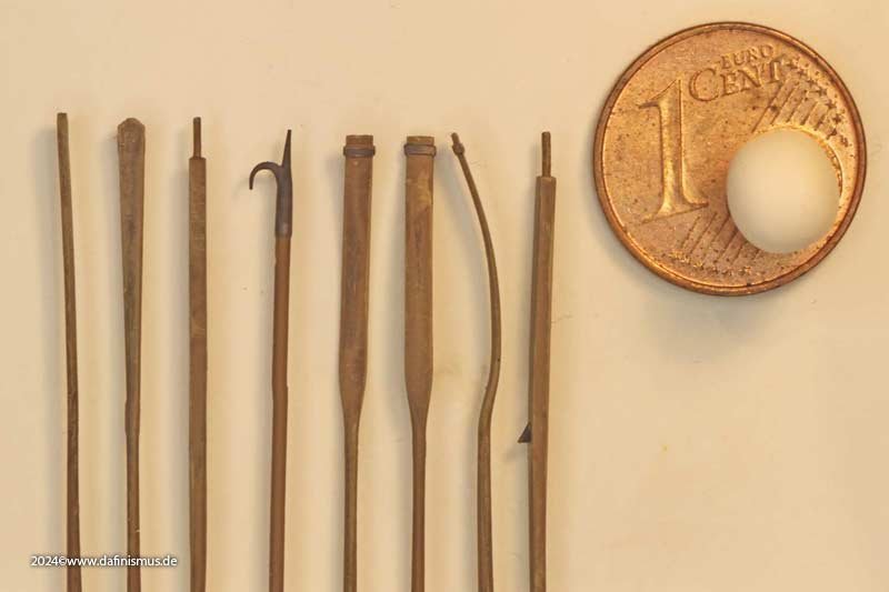
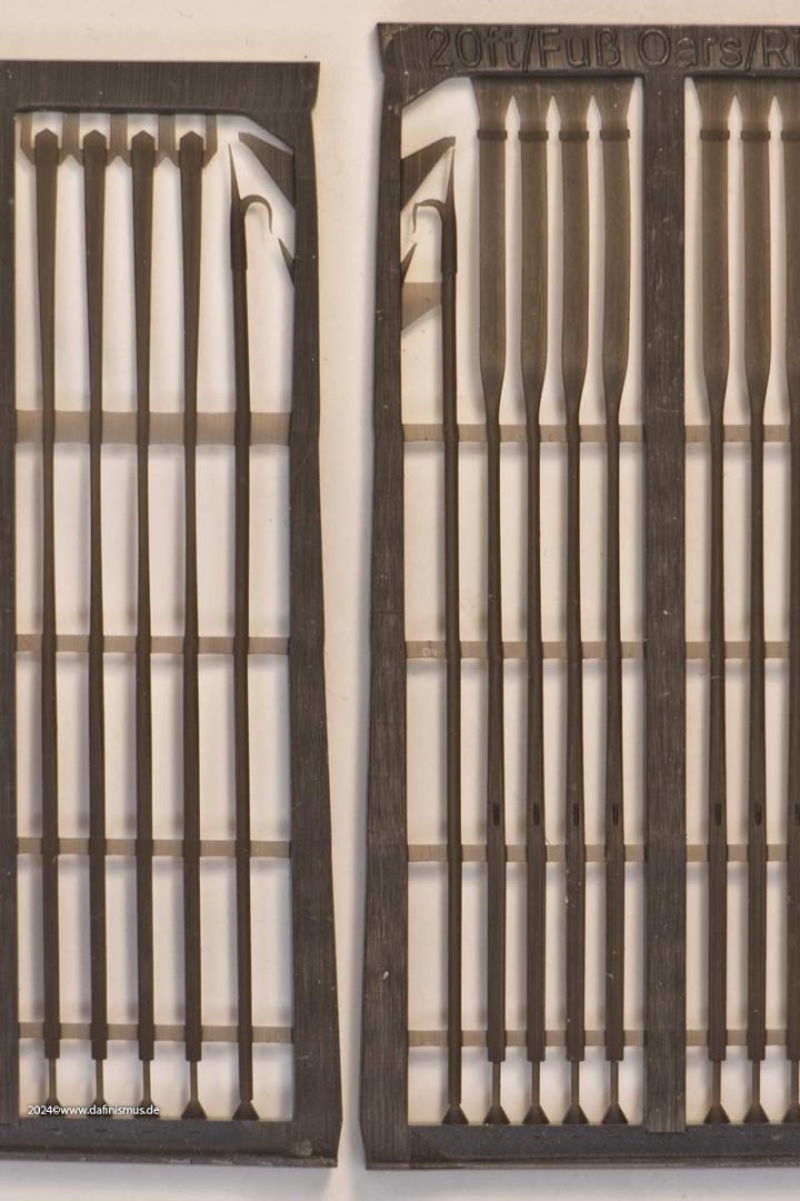
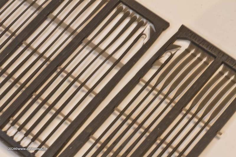
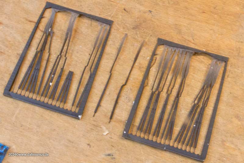
Parallel to the 1803 ad 1910 Vics, I have been working on the boats. Or rather on the oars. The trigger was once again the "egytian paddles" that had found their way onto an otherwise great model. To start with I did not yet get in contact about that topic. How long? What form? I had no idea. Hope you will be able to cofirm the ext steps. Fortunately, I was given quite fast a reference to David Steel's "The art of Making Masts, Yards, Gaffs, Booms, Blocks, and Oars, as Practised in the Royal Navy, and According to the Most Approved Methods in the ... of an Improved Rule for Mast-makers", a volume I wasn´t aware of before. I just ordered my copy as I found no official legal online source. In there the relevant iformatios were given in 4 tables. Oar-Making The different parts of oars are described by the engraved figures, and their dimensions by the tables. Ships’ sweeps and oars are made of hand-masts, or rafters, suited to the size and length, as per table. They should be chosen straight-grained, free from large knots, shakes, or rind-galls. They are first sawed, or jambed in a snatch-block, and hewed nearly to their size; then raised on horses, and completed by the drawing-knife, spoke-shave, or plane. Open handles are nailed to the sides of the loom in the direction of the flat of the blade, made of oak, about one inch and three-quarters deep, and two inches and one-quarter thick, hollowed to admit the hand easy between that and the loom: the length of the handle is one-third the length of the loom. Barges’, lighters’ and ships’ boats’, oars are made of fir-rafters, similar to ships’, without handles to the sides of the loom. N.B. The looms of boats’ oars are often made round. Oars and sculls for barges, wherries, and skiffs, are made of ash (and sometimes of fir) rafters, which should be chosen tough, straight-grained, without shakes or large knots. The rough wood is taken off with an axe, and finished in a neat manner on horses by drawing-knives, spoke-shaves, and planes. A leather button is nailed on the foreside, about two inches from the loom, and that edge rounded, to work easily in the rowlock: the lower end of the blade is strapped round with tin to prevent its splitting. Sculls for wherries, skiffs, &c. for choice and make are similar to wherries’ oars. The sizes relevant for my Victory boats are the sweeps for the larger workboats with straight blades and the oars with curved blades for the smaller boats. First the sweeps. They have an interesting shape. The thin round handle, the square loom, the round to elliptical shank which then transitions back into the flat of the blade. And here is the oar. Here the design is even more differentiated: round handle, rectangular loom, elliptical shank and the curved flat blade. Here, contemporary models are much more relaxed in the curve, which is why I have not shaped it as extremly as seen in Steel. Also the blades have a reinforcement against splintering on the outer end, in the contemporary models usually formed as a ring and not over the edge as with Steel. And, as always, the fallacy: It's programmed, so it can be printed straight away 🙂 Shull bit. It took a lot of convincing, but in the end something useful came out. Then some more color, dark brown primer and a lighter tone as brushing. And to top it all off, a close-up 🙂 If compared to the model oars and sweeps in RGM it seems the right direction. Still puzzeled about the triangular piece of leather that keeps the oar in place. How did it look and how was it fixed? All the best, DAniel XXXDA


-
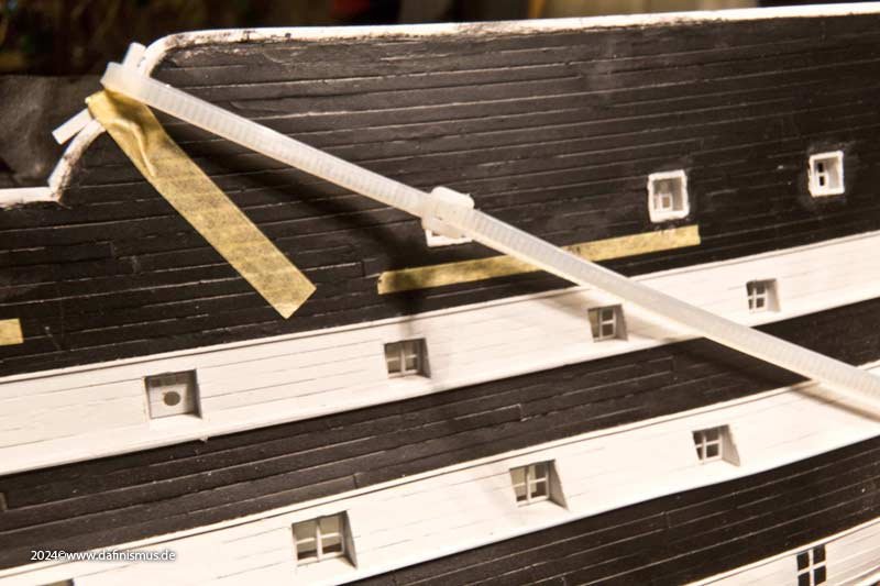
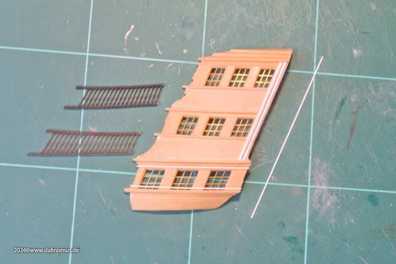
Made a little progress over the last few days. First planked the poop railing, then built the curved end to the aft deck railing, pressed on the end strip using cable ties. Then sanded down the balusters on the side pocket, which has become quite fast. First built the dominant vertical rear end profile. Then came the other window frames. The whole thing sprayed and the white balusters glued on ... ... and then - oh horror - ... ... ... ... XXXDAn
-
Also Trafalgar was won by the French. At least in Napoleon’s newspapers. Also do not forget personal or political „corrections“, famous today still as alternative fakts or fake news. So nothing was learned since then. Also the eyewitnesses had their own apperception from a special moment or a made up memory as part of trauma or time that passed. So it is always a good starting point for a new research, a new thesis or to confirm the old known facts in spite of the new input 🙂 But sometimes something new really pops up . XXXDAn
-
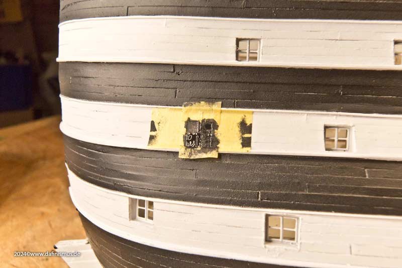
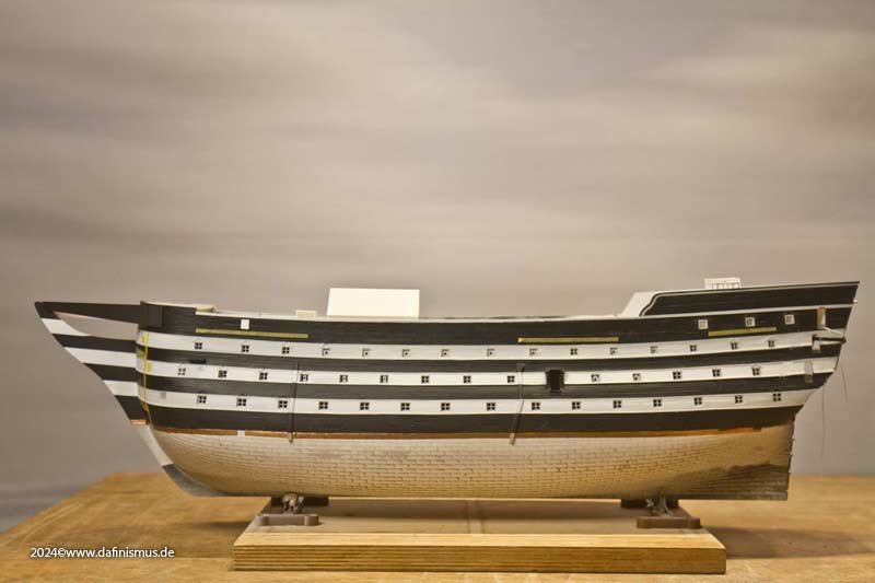
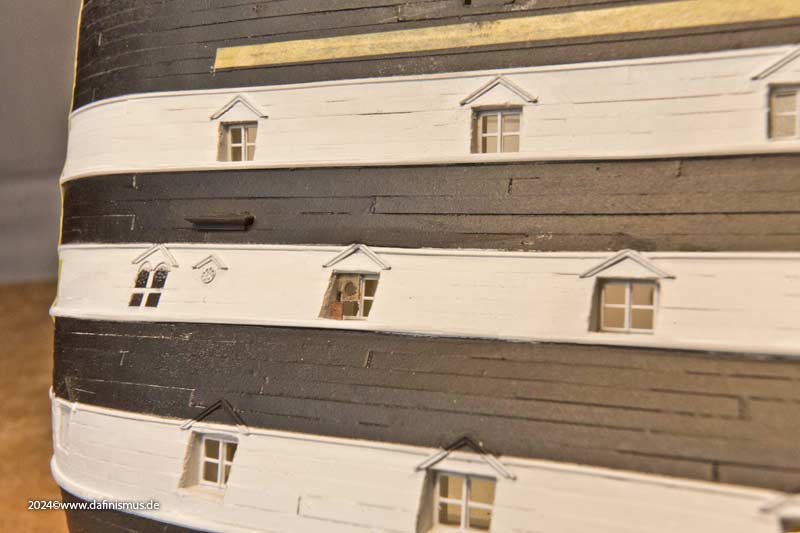
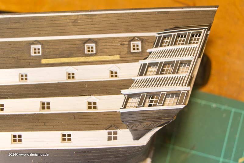
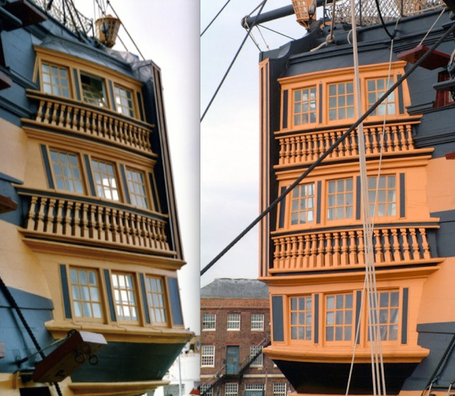
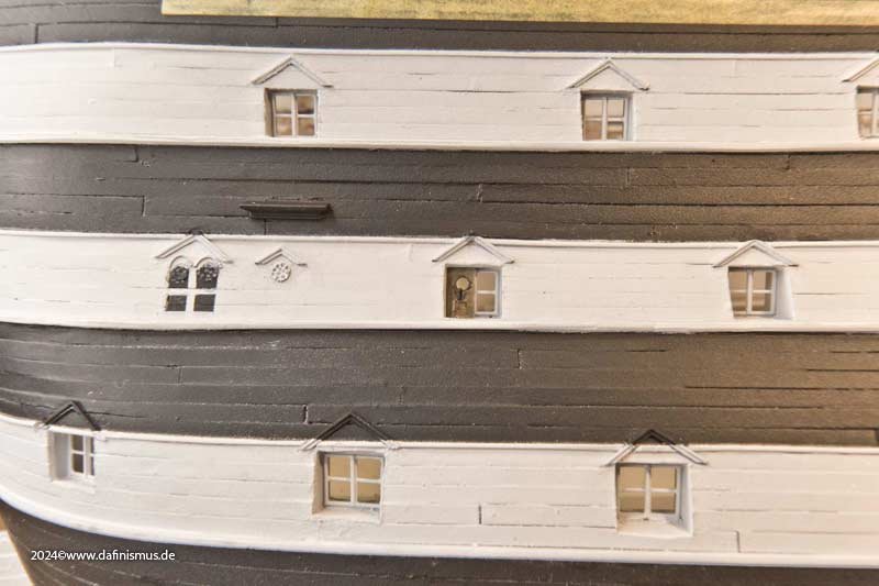
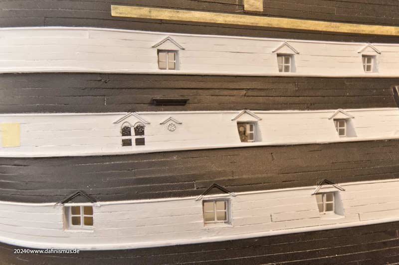
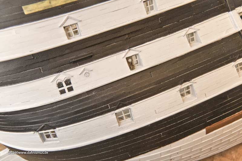
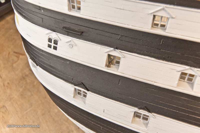
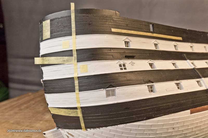
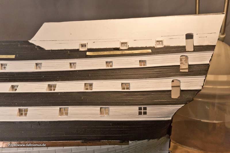
I also believe that those discrepancies seen today are simply much more a result of uneven build. As an excuse, the geometrie there is not that easy 🙂 Also one sees that the hull as base is not that even anyway, as the wales in the middle tier seems to have different widths. Compare the black lines and the edges. McKay was often critisised for showing the wales applied onto the planking, but he only shows what was the state of build in those days. This is not to bash his superbe work but only tells one thing: The exhibit in Portsmouth is a wonderful inspiration, gives a great view to the general public, is well kept over the years regarding the resources in research, available material and manpower and most important budget. I am more than happy and enjoyed having been able to visit her several times and thanking all those people involved over the last 200 years. But ... ... my personal conclusion - that took me several years to realize - for modelling on a higher level forget the exhibit there and go back to the sources. Many of the things that I had to replace on my build were inspired by anachronistic features shown there. 🙂 XXXDAn PS: And I am waiting for the shockwave that Gary still will create 😉
-
Hello Kevin, thank you for pointimg that out. To be honest, never realized too much of a difference ... What I see is the usual discrepancies if parts are build without too much planning. OK Vasa was worse 😉 I know that she had a collision with HMS Goliath on 03.04.1797 that damaged the stern Galeries, lantherns and cutter. 1803 the stern was completely changed. At Trafalgar the starboard gallery was crashed by the Redoutable. Also there was a great makeover of the stern somewhere inbetween 1816/1820/1828/1860ies as first photographies show a different stern compared to the post Trafalgar drawings. And in the 1920 there was the retrofit for Trafalgar state where the galleries changed appaerance again. And McGowan shows a picture of about 1970-1980 with the larboard gallery dismanteled. So one sees there were many opportunities to mess up with the design of the galleries 😉 They are far off the elegant look they had as build. 😞😞😞 XXXDAn
-
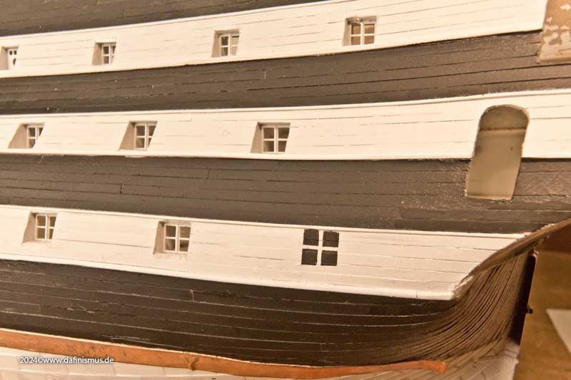
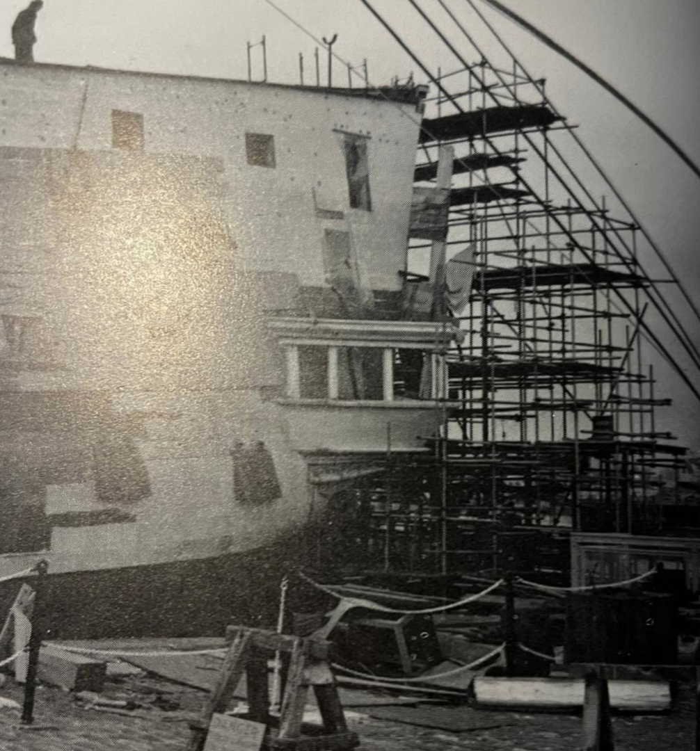
Oh yes Jan, she was in a pitiful state. That is why she had to be removed into the drydock in 1920. One of those responsible for the restoration, during which it was returned from black and white to its "Trafalgar state", remarked at the time that he could simply push through the hull in several places with his walking stick (an indispensable life-style product of noblesse at the time). That must have been one of the places. According to my guess, this area must have housed the sanitary facilities and therefore also the shower. The resulting humid climate - together with the hormone-fertilized, corrosive sweat exhalations of young sailors - may have been responsible for the desolate condition of the ship at this spot. If you look closely at the old pictures, you can see small straight rows of dots and a difference in color. This shows that this area was covered with a few patches of painted canvas until shortly before the photo was taken. Another way to hold a ship together 😉 If I will show the canvas or if I suggest that in 1910, the state shown in the model, means before the great war, the ship was still in a slightly better condition, I do not know yet. Depends much upon the way the results of imitating the canvas turns out. XXDAn
-
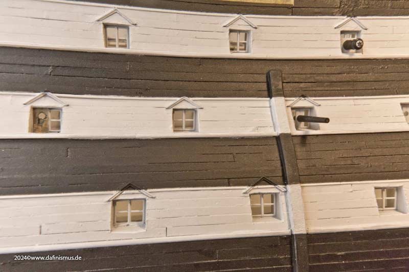
The rigols have also found their way onto the model. Here still in the stack ... ... and here already at the scene of the crime. My favorite detail 🙂 But I saw afterwards that the wooden panel only covers the top panel, so I'll probably have to touch that up again. The area of the hase bolsters has already been marked on the bow and the prison cell has also been given its bars ... ... and the windows under the poop also got their window frames. XXXDAn
-
Hello Leo (?) on the pictures most of he inside is still scrach build, but most parts are already available as print. I use my scratch prototypes as template for the CAD, as I modify the original plans to fit the different appearence of the scale concerning the accentuation of the details. All the best, DAniel
-
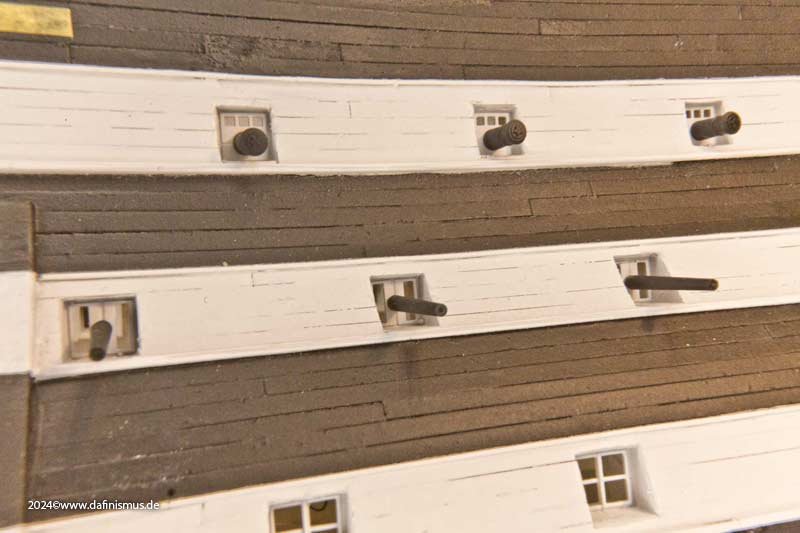
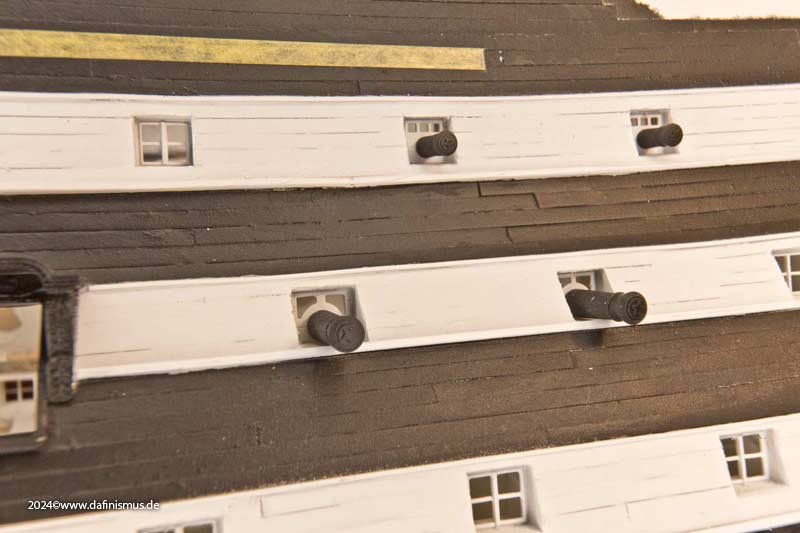
And because it was so beautiful, we went straight on. Some of the ports have been planked up over the years. So that it still looks very well-fortified ... ... the missing windows were simply painted on. Honi soit qui mal y pense. The artillery has also found its way to the dressed rehearsal. In front are the three signal cannons for the salute, above them short 12-pounders from dubious historical stocks ... ... and amidships the historic Trafalgar guns - or what they were considered to be at the time 😉 And before the questions come, yes, the barrels did indeed sit on the lower portframe back then. Improperly executed changes to the port dimensions and incorrect carriages ... XXXDAn