dafi
-
Posts
2,416 -
Joined
-
Last visited
Content Type
Profiles
Forums
Gallery
Events
Everything posted by dafi
-
 My personal theory is that the english ships were build strong enough to have the stanchions removed under normal conditions when using the capstan. As for my understanding, in heavy weather those wooden stanchions can stand much more pressure from the structures above than the thin iron ones could, there is more likely the danger of just bending aside if pressure gets to big. I often read the english comment about the french ships not being that resistant to extreme conditions, perhaps for details like this. XXXDAn
 -
Blaise Olivier was joking about the english having to lift the deck beams to unlock the wooden stanchions and refers to the french ones that were iron and could be swung up. Afterwards the jack is taken out too. There are also smaller iron jacks, but this is the one Olivier refers to in his book. Reasoning for why the english chose that complicated way? The only reason I see is that the wooden stanchions could handle nuch more pressure than the thinner iron ones. As always open for other or better ideas 😉 XXXDAn
-
And to finish off this wonderful conglomerate, the manropes were added, the railings so to speak. A template helps with the knot, by opening and closing a pair of pointed tweezers, the knot can easily be moved sideways ... ... and the eyebolt was also placed to size. Then the small net so that the jib sails don't get caught under the spars. First clamped in a cardboard frame ... ... then primed with white and tinted with brown. Then glued on a frame of twisted wire ... ...and cut it out. Then fastened the manropes ... ...and sewed the netting onto them. And immediately sent up a sailor to test it. It's just a corner that was a lot of fun! And here you can see my foolish luck: The hearts have the big distance to the bowsprite, because the jib boom has to be pushed through :-0 XXXDAn
-
The next thing was of course a matter of heart. Fixing the stay of the foremast was still easy. To avoid having to wrap the thick stay around the bowsprit, a half-sod cable was used twice as a counterpart. The heart has two side grooves, in the first one the rope was glued in, the length of which I had previously measured with a test piece. Then the rope was looped into the second groove. The cut of the rope is later elegantly covered by the strapping. The two loops are then tied together under the bowsprit. The upper heart on the stay is tied in the classic way like the deadeyes and the excess is lashed on. The excess serves in case the stay has to be spliced. If the stay brakes, the somewhat thinner preventer stay above serves to keep reminders up. Thats why I will later on still sneak them together. A break of the stay has actually happened to the Vic before: On 19.09.1797, the mainstay below the Maus broke in a storm. An auxiliary stay was built from tackles and with a hawser, and the topmast was lowered. In these pictures I was still wondering about the large distance between the lower hearts and the bowsprit. However, my foolish luck prevented me from shortening them a little. The resolution follows. It got funny with the two stays of the main mast. As with the gammoning, I didn't want to disturb anyone doing urgent business there. Only this time I had an extremely balky 1.1 mm cable, which had to go through 1.3 mm holes and twice around a right angle. The Großborgmain preventer stay was also delightful. First of all, finding the right length on the model ... ... and served as usual. This time not double, but in the same thickness as its counterpart above the hearts. But it should be tied together at the bottom, but there is hardly any room to get through under the bowsprit - Ohschockschwerenot - OMG! So I threaded the auxiliary yarn through and pulled the collar along. I pushed it also through with tweezers until I could reach the eye on the other side, tied it and rotated the whole thing back again. Uffz! But the sight is comforting. The view of the surroundings too, everyone survived. And then there are the lanyards to keep the hearts together. XXXDAn
-
The big sailing ship exhibition in Amsterdam is getting closer, I'm already looking forward to it. I'm going there this weekend and on Saturday my little one will be able to present herself and her bee stripes at the Naval Museum in Amsterdam. Maybe one or the other can come to visit at short notice, I think it will be bombastic. This special location, almost 130 running metres of exhibit tables with over 250 sailing ship models. WOW! Time to stay? No, time for the stays. The pictures of the Invincible wreck beautifully show that the mainstay and forestay and associated preventer stays were dressed differently. The main and forestay were wormed along their entire length. Only in the area of the mouse and the masthead was it was served. The preventer stays weres also fully served in the area of the mouse and masthead, but not wormed along its length. It's not often that you find mice with hearts, so I don't want to deprive you 😉 Pictures of the Invincible 1745-websites. So it was off to the serving machine, first worming the stays. You can see that the cable - which consists of several beaten ropes - now looks much rounder and more even. I used the serving machine also for serving itself. For this I took 3/0 fly fishing yarn, it fluffs up just like tooth floss, so you can easily overlap windings. After that I used white glue to smooth surface more and some black paint for the surface appearance. Here a picture of the seam between wormed and served. For the eye, I cut the cable diagonally and glued it on, and dressed the glued area with fly fishing thread. It is quite stabe like this. And then came the mouse. First wound ... ... then glued ... ... and then homogenised with black. And at the place it looks like this. Classically, one mouse on the left, one on the right. The shrouds still belong under the stay, but I haven't got that far yet. That's why I'll just take the stays off again and put them on top as soon as I'm ready. XXXDAn
-
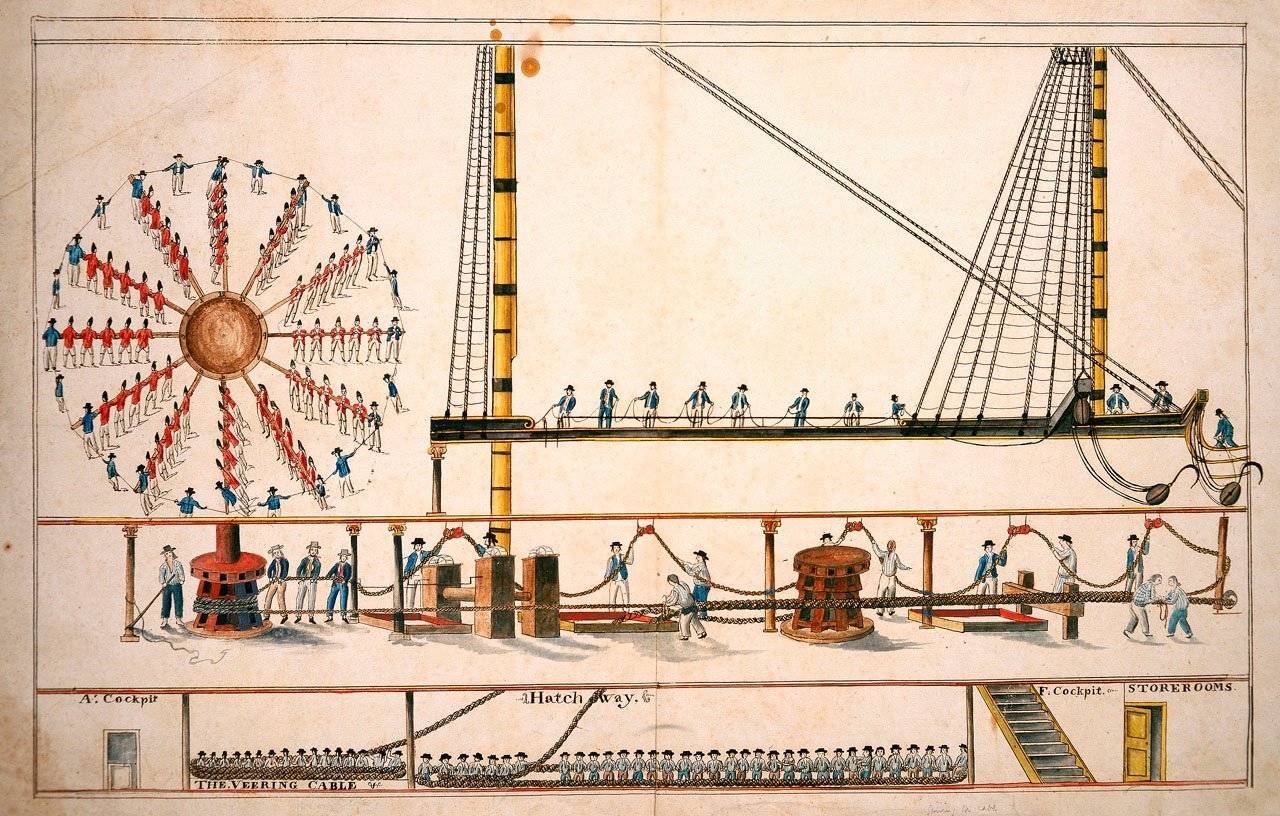
If not needed on deck, the Marines still had some other helping tasks: Manning the guns and the capstan 🙂 XXXDAn
-
Thank you druxey and etubino! But firstly, I'm stupid and secondly, I need glasses ... Thanks to the many tips from modelling friends, I know that I had misinterpreted McKay's drawing. Of course it is correct 🙂 So here comes another demolition. In the meantime, I no longer print the blocks sorted by type but by yard. There are still some blocks missing, but 2 of these sets contain everything for the main yard. Slowly it is routine and goes quickly by hand, glueing one rope into the groove of the block ... ... then the second one into the other, so that the short ends are diagonally opposite each other. Then the whole thing into the holding device, a drop of superglue in the middle and press them together vertically ... ... and horizontally with a pair of strong tweezers. Then tie a safety knot close to the block. Then cut the short ends as short as possible. Then set the averaged length for the short loop, bring the rope to length, and fix it with a drop of glue and press it together again with the tweezers. Check length. Adjust long loop and do the same. Then the whole thing should already be stable enough to make a trial fit at the place of use - here it is fitting. Then, with the specified distance of 4 mm from the block, set a knot with long enough ends for the binding and then line up normal knots close together alternately at the top and bottom all the way up to the block. It's quick and, unlike the standard wrapping, nothing slips out of place. Add a little paint to defuse the white glue spots ... ... and two neat block strops are ready. Still tying up the lanyard ... ... set the whole thing in place and sew in the lashing with a needle. The inner lying sheet block had already found its way to the yard :-) After that, it was the turn of the clew garnet blocks. And then one can recoice 🙂 Hopefully it fits this time 🙂 XXXDAn
-
FULMINANT by HAIIAPHNK - French stern castle
dafi replied to HAIIAPHNK's topic in - Build logs for subjects built 1501 - 1750
Just to keep up the discussion. Not having had finished yet the reading, my preferences immediately came up with a male musculous figure, either Zeus, Poseidon, Mars, Hercules, Arnie or soemthing alike: FULMINAT ! If I remember well, this was the time when the name of the ship was still symolised in a very special figure on the bow and not yet an anonymous design. One of the old and mighty gods would do for me 😉 XXXDAn -
As always, first check whether plans show really can be. You should. Really. Somehow it seemed strange to me that the jeers block had a double strop at the top and a single strop underneath the binding. What to do with the two unused ends? No use, or not much use. So I looked in other literature and, lo and behold, everywhere a double strop is shown at the bottom. Makes sense. So I tore off the wrong strop and glued on the double strop with the right lengths, in one groove the rope for the two shorter legs, in the other the rope for the two long ones. Then made the seizing that holds all 4 ends together. Then tied in the eyes for the shorter legs. And then the ones for the long legs. And suddenly ... ... the model parts come to life 🙂 XXXDAn
-
Thank you druxey for your confimation. Very appreciated! A little project in between, the Vic's fire buckets on the railing of the cabin deck. And since the good pieces are made of leather and not metal, I gave them a little deformation as a little dafinistic touch. XXXDAn
-
The second collar conglomerate was quickly done, the third - the foremost one - bobstay was exciting again. There are 2 versions here. First, in white yarn, a temporary test version like the one McKay shows in his book. The doubled stay goes down to the cutwater, is tied together there and then goes left and right to the hull. It used to be shown like this on the Vic in P. I assume this is how the pulling force is distributed better among other stable components. Alternatively, there is also the variant where the 3 stays on top of each other all go to the cutwater. During the last renovation the Vic in P. was also converted in this way. The attachment points of the bobstays at the top of the bowsprit are well documented. Only the attachment to the cutwater is not. In later years, only the variant with the 3 superimposed holes was found, also due to the feedback from @Morgan, who knows the Vic around 1803 best, I tend towards this solution, which I also prefer, as it was last shown on the Vic in P. See more of the discussion here: https://modelshipworld.com/topic/35115- ... nt=1003053 So the white test stay was cut off and the third hole drilled. The heart is tied into the stay in such a way that one leg ends exactly under the binding and the other is more than twice as long. Then I threaded the stay through the hole, averaged out the length and glued it to the top of the heart just below the other end and then put the binding over the intersection. Then I put the binding at the bottom of the stay, so that I can even out the length of the two legs if one side is a bit loose. Afterwards, as usual, I replaced the white tackle at the top with the final lanyard, which has become quite fast work by now http://www.shipmodels.info/mws_forum/images/smilies/icon_smile.gif And here are a few more views of the collar conglomerate. Now the forestay and the preventer forestay are missing, each sitting in front of the two inner collar rings. XXXDAn
-
Thank you Sirs, as always, very appreciated! @Hubrac: be aware, binding technique is the same, but none of these features are to be found on your Soleil, as they are much more recent 🙂 XXXDAn
-
Thinking things through: Victorys bobstays
dafi replied to dafi's topic in Masting, rigging and sails
More to this Topic: Even if i strongly beliebe that ZAZ 0513 is Union class and not Victory, i think the details can be strongly considered. Still the doubling of the hawse area looks strange. But there is still ZAZ0517 that gives a good idea about a possible bow structure. -
Thinking things through: Victorys bobstays
dafi replied to dafi's topic in Masting, rigging and sails
Thank you Keith. Unfortunately I found no sources about the provenience of this picture. Did I oversee it in the book? XXXDAn -
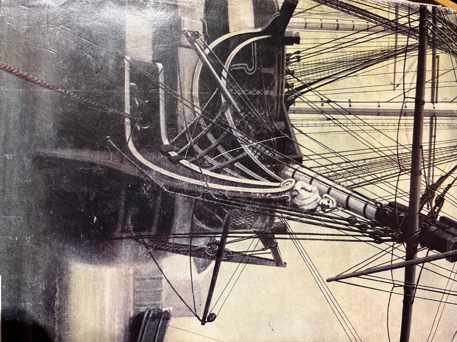
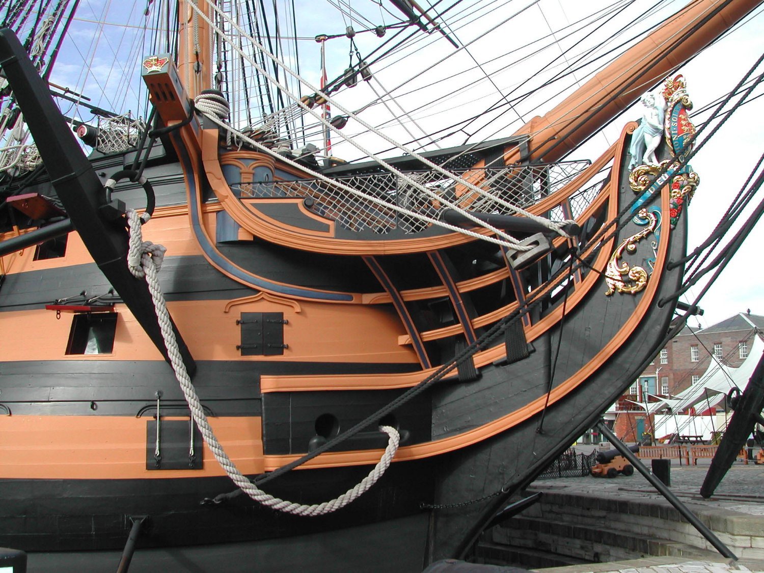
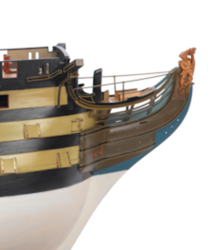
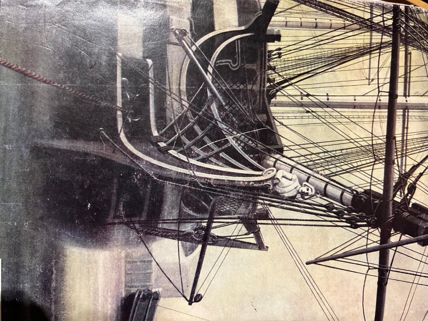
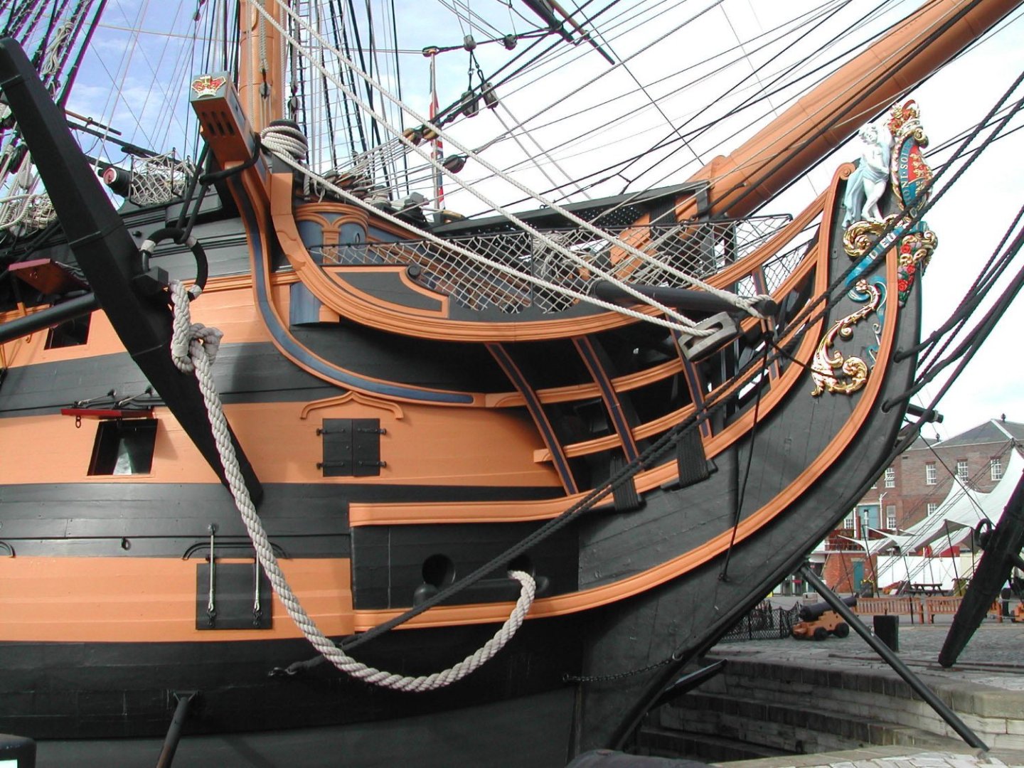
Hello again, looking for the set of Victorys bobstays. Especially then foremost one. The two inner bobstays are lead into holes in the knee of the head and then spliced. For many years the Vic in P had the foremost bobstay - officially allowed from 14th May 1800 on - with long legs, equal in length. A round seizing holds the legs together where they touch the foreside of the knee of the head. They then diverge. The ends have a thimble and hook spliced in by which they were attached to exye bolts inth bows just below the lower deck. (Longridge) This con be seen on the reverse sleeve of Longridge´s book "Anatomy of Nelson´s ships" Here the picture that Longridge uses and the same on the Vic in P. Since the last restauration, the long legs were skipped for a third hokle for the stay just underneath the other two ones. Also this is shown in ZAZ0513 with is indicated to show Victory in 1803 but where I strongly believe this was HMS Union of 96 guns. Netherthekless, this model is giving good hints for the Victory of 1803. Which is the more plausible version for 1803? All the best, Daniel
-
And the adventure continued. Many attempts were made to dress the thin ropes: first rope wrapped in the classic way, various diameter combinations, resulting in extremely high workload, extremely high rejects, when bending around the blocks the tapes broke open and above all: it looked like crap somehow ... I also wrapped the thinnest wire with copper thread and blackened it, the same result, but it looked even crappier. After many attempts, I decided to use an imitation with 3 layers of white glue and black paint for the dressing of the thin ropes. Then it was on to the impressive head gear. First comes the collar for the bobstay, then starboard and then port shroud and in front of that the stays of the foremast. Three of these rows of cleats have to be filled. The hearts were tied into the stays using the same binding principle as the thimbles. I still had to feel my way around the first one ... ... and the next ones went very quick 🙂 The tying of the collars was again a good fiddling job, because the tying does not slip or even out. You just have to get it right from the start. But when I thought that was fiddling, open-heart surgery was performed, even though these hearts were closed: The tying of the lanyards into the hearts. Because the hearts only have one big opening with 4 grooves and no separate holes, you have to secure the rope with glue after each new loop so that the lanyard doesn't jump out of the groove again. But once you've done that, the sight is just sha 🙂 This was the first of the 3 collars, two more to go 🙂 XXXDAn
-
When I was working on the main yard, I noticed that I was missing good jeer blocks. So I programmed and printed some right away. And the hearts for the stays and the head gear also came with them. And since that went so well, the other special blocks were also added, here the shoulder and sheet blocks. In the past, I had made the thimbles from pierced and drawn sprue at great effort. Printed is quicker and cleaner and above all more true to size. Then the moment of truth: Binding the thimbles, here the 1.75 mm size: Apply a drop of superglue with an applicator to the back of the thimble in the groove ... ... and hook the rope into the groove at the back of the thimble and pull it forward. Then I pressed the rope together at the front with some glue using tweezers and pinned the thread for the splice imitation at the desired distance from the thimble and fixed it with slow super glue. Then knot the two ends alternately at the top and bottom, always moving the knots in the direction of the thimble until the gap was closed. Then the final knot was secured with glue and cut off the excess lengths. With the pointed tweezers it goes really fast. Using an almost dry brush, brush on some black paint to cover up any light glue residue. Then cut open one of the hooks from my etched parts set at the eye, bent it open and inserted it, ... ... bent shut and that's it. Here are the patterns for 2 mm, 1.75 mm and 1.5 mm. They are also used in a not entirely uncritical place, the bumkin shrouds. It is difficult here to produce the right lengths so that it fits on both sides and also looks the same. Here, the shoulder block for the foresail's tack is tied in. This is then the set. And this is how it looks in place. XXXDAn
-
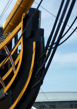
Somehow I always like screwing myself. Like when I enthusiastically ordered the crew to the heads for their relief. I had simply put aside all the heads gear :-0 So I put the sling for the gammoning over the bowsprit and threaded all the lashings with the 50 cm long and still quite balky rope through the crew like this ... ... so that no one felt inconvenienced in their businesses or even knocked off their thrones. Somehow I actually managed without any accidents. Afterwards, I had brushed the gammoning minimally with white paint to match the colour of the rest of the appearance. When I looked at the lower edge of the gammoning, I noticed the hawse pipes. I had already had the pleasure of looking at an original of the St. George in Thorsminde. These were made of lead with a nice bead around the outside. It took me a few attempts to find the right material for it. I ended up with 0.4 mm copper wire, which was hammered flat to lose the wire character. Fitted, glued on ... ... and painted. XXXDAn
-
A completely different construction project that I've been sneaking around for a long time: I finally got to work on the main yard. All fittings were better articulated ... ... the lunettes for the stun´sail spars come from my etched parts set ... ... and as always: The colour makes the difference 🙂 According to Lee, in wartime the rope hangers were replaced by a chain. I think 1803 to 1805 might count as wartime. I still made the chain hanger the right length and added a shackle to make it easy to hook and unhook the yard. And only in the sideways position you can really see what a big hulk it was :-0 Our little dreamy midshipman has also returned to his favourite spot. XXXDAn
-
Why noble? Just a hard working englisch officer 🙂 https://en.wikipedia.org/wiki/John_Pasco XXXDAn
-
Thank you Gentlemen for the likes! In our German forum there was a serious reference to the uniforms of the two gentlemen. Both gentlemen without headgear? A "Ça ne va pas" as the Italian would say. The headgear was an integral part of the uniform and could officially only be removed indoors. And the laps of the uniform were too short, or the slit not high enough. Well, let's make Lt. Pasco happy :-) In the meantime, I've had enough practice building those little hats. Then I extended the laps upwards, removed the white border at the bottom and both men are well behated. Instead of the detached hat on the flag box, a flagbook or notebook ended up there. I hope that Lieutenant Pasco can now go about his duties with peace of mind :-) XXXDAn
-
In the meantime, Lieutenant John Pasco and his assistant have also arrived at their workplace on the poop deck. The canvas curtains in front of the flag lockers have been drawn back ... ... but oh horror, they are all empty! So quickly placed a bulk order of the current signal flags, 64 pieces, carved from 1.5 x 1.5 mm plastic strip, about 2 mm long, in the colors of the 1803 signal flags. Then covered the hull so no one would get hit by falling flags in the gunroom ... ... and generously assisted him in filling it. One more brief inspection of the result ... ... the flags at the top of the locker secured with weight bags to prevent them from flying away ... ... and he can prepare his flags well ... ... for, after all, it will be him who will translate Nelson's pre-battle greetings to his fleet into usable signals: "England expects that every man will do his duty." XXXDAn
-
dafi Post subject: Re: To HMS Victory and beyond http://www.shipmodels.info/mws_forum/styles/subsilver2/imageset/icon_post_target.gifPosted: Mon Aug 14, 2023 3:21 am http://www.shipmodels.info/mws_forum/styles/subsilver2/imageset/en/icon_user_online.gif http://www.shipmodels.info/mws_forum/images/avatars/gallery/MW-custom/shipyard%20worker.gif Joined: Mon Mar 12, 2012 11:13 am Posts: 865 Location: Ludwigsburg/Germany It went meanwhile to the hammock tinkering. I rolled the hammocks as already seen of my cut versions with spacers out of Fimo into the right diameter and rolled in the structure with a rake, folded and baked them. A little color ... ... and shading ... and whoopee into the hammock cranes ... ... and ready it is. From the quarterdeck it looks like this. Maybe I'll send the guys to wash the hammocks some more, the washing is a bit heavy, but how clean were the mats actually back then, so before the days of washing machines and chlorine bleach? XXXDAn
-
Nowadays at the Vic in P., the rudder pendant goes up to the mizzen chains and is secured there with a toggle. There is an interesting detail on the contemporary model SLR0512 of the Victory: The rudder pendant goes up through the channel board to the poop deck, is routed aft at deck level, and is tied to a cleat further aft. This way, in an emergency, the line is quickly ready for use and does not have to be extended as it is today. A detail I wanted to install for a long time, now it was finally done 🙂 XXXDAn