HOLIDAY DONATION DRIVE - SUPPORT MSW - DO YOUR PART TO KEEP THIS GREAT FORUM GOING! (89 donations so far out of 49,000 members - C'mon guys!)
×


dafi
-
Posts
2,426 -
Joined
-
Last visited
Content Type
Profiles
Forums
Gallery
Events
Everything posted by dafi
-

British Pathe film: Model Boat Building, 1956.
dafi replied to uss frolick's topic in Nautical/Naval History
I love the suit although the tye is missing - I think it is time to bring back a bit of style back into our workshops - Just ask Jeeves 😉 With me, the table would be scrap after one tinkering session. But it is amazing with what somnambulistic confidence he prepares the parts, simply stunning! Also the way he takes the measures from the pictures, simply a compass. Of course some might be fake for the TV, but still it is a great testimonial of the ancient kind of modelers. All the best, Daniel ... gone to look for his tye ... -
A small test I did for my Heller Victory ages ago: Same dimensions, same weights. Guess which one is the original plastic kit´s part and which the wooden replacement 😉 XXXDAn
-
The next adventure and small intermezzo were the blocks under the fore fighting top. Here, leech- and buntline run colorfully mixed with the braces of the sprite sail yard and top yard through a wonderful collection of blocks. The first attempt was the classic way of doing the strop first ... ... and then pull it through to the top from below and push the toggle through the upper loop. It worked, but it was a rather messy and uneven act. Then prepared another block, but didn't tie the top loop ... ... and pushed the free end from the bottom to the top, tied a loop there with an auxiliary thread and brought the free end back down. Now I was able to pull the loop at the top tight from below, insert the toggle and adjust the length with the free ends of the binding, knot everything and neaten the whole thing. It looks much better http://www.shipmodels.info/mws_forum/images/smilies/icon_smile.gif You can see the 3 different blocks, with the outer one having two differently sized wheels. This is due to the fact that there are four rope thicknesses in use at this point, resulting in simply beautiful details. And it also looks very tidy from above. And if one wonders about the different layout of the battens, very simple: the Admirality Order from 20. Nov.1802 defines the tops of great ships to be done out of fir instead of oak and to be fitted in two halves http://www.shipmodels.info/mws_forum/images/smilies/icon_smile.gif This made the tops less haevy and far more easy to be exchanged if damaged. Yay! XXXDAn
-
A small end of rope did the job 🙂 That is why the ropes are measured in cicumference and not in diameter as we usually do. Many modelers already fell in that trap. XXXDAn
-
The main yard was finally also finished so far, here is an overview of the collection of all the blocks that have now snuggled together. Always seen from both the front and the aft. And as already written earlier, the stirrups and foot horses will only be smoothed and provided with gravity during the final installation. The center of the yard with the chain sling ... ... and the yard arm, 9 blocks in 8 sizes :-0 Then came the exciting moment, the test hanging http://www.shipmodels.info/mws_forum/images/smilies/icon_smile.gif First the lifts. Then the yard tackles with outer tricing line. And usually as last the braces. And there is another little tidbit that is not normally seen on models. According to Steel, the rope slings were replaced by chain slings in wartime, as can be seen in the pictures of the lifts. Consequently, the forward-facing preventer braces should also be fitted. These replaced the double pendant of the braces of the 1760s. For this purpose, the brace was attached to the rearmost shroud of the foremast, ran to a block on the front of the yard, back to a block on the rearmost shroud and from there to the forecastle. Exciting. XXXDAn
-
... and already Steel is a mere collection*** of earlier works that were simply updated. XXXDAn And those earlier works the same ... ... and later works too ...
-
Yepp, it is Lees where I found it first, then being confimed by the find at Steel. By this resaerch it became quite obvious that Lees uses quite a lot of Steels informations, sometimes word by word. (This is not a moan 🙂 ). These details can be found in Part III "Progressive Method of Rigging Ships" in the article of "Rigging the the Lower-Yards" in the passage about Fore- and- Main-Braces, Preventer-Braces and Slings. Also most of these details are repeated in the "Tables of the Dimensions of ..." in the sections for lower fore mast and lower main mast. XXXDAn
-
And another little tid bit that is not normally seen on models. According to Steel, the rope slings were replaced by chain slings in wartime. And if "the road to Trafalgar" doesn't count as wartime, what does ?!? Here you can also see that the chain sits on a wedge at the back, whereas the rope slings is passed over the bolster of the mast head. Until 1760, the braces were supported by preventer braces, whereby the hanger was doubled. However, as this proximity was certainly not as effective when under fire, the preventer brace was later brought to the front of the yard. Consequently, since the chains are attached here, the forward-facing preventer braces should also be attached. For this purpose, the standing part of the brace was attached to the rearmost shroud of the foremast, ran to a block on the front of the yard, back to a block on the rearmost shroud and from there to the forecastle. Exciting. XXXDAn
-
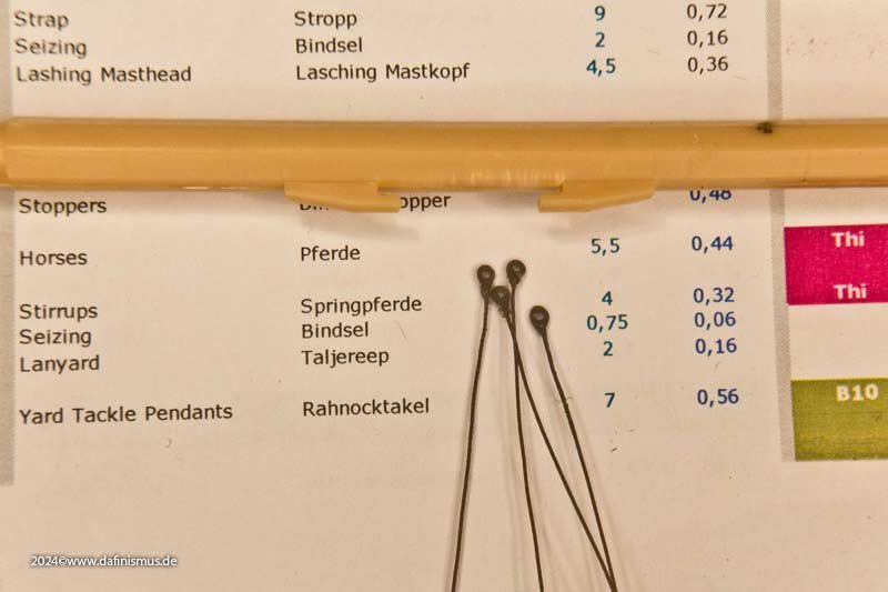
And at some point we got serious with the foot horses. First the thimbles were tied into the stirrups and the four-pack on each side was secured against being breathed away. For the research of the length of the stirrups please look here: https://www.mediaharmonists.de/bilder/Sammler39/Victory-Blocks-240415_8487.jpg Then average out the distances for the stirrups. https://www.mediaharmonists.de/bilder/Sammler39/Victory-Blocks-240415_8489.jpg For the distance between the thimble and the upper reference point, I made a small 9 mm gauge so that the distance is even when being glued down. Then 3 turns with the free end and glued that on too. When all 4 stirrups were in place, the foot horse was pulled through the thimbles and secured with an external knot before and after the thimble to prevent it from slipping through. https://www.mediaharmonists.de/bilder/Sammler39/Victory-Blocks-240415_8495.jpg Then a short standing test, and lo and behold, it looks quite plausible. https://www.mediaharmonists.de/bilder/Sammler39/Victory-Blocks-240416_8507.jpg Then knotted the eye on the inside of the foot horse to secure it. It was THE perfect eye. But I had overlooked the fact that the clamp on the other side of the yardarm went further out than expected, see orange thread ... ... so I cut off the eye and spliced in an extension, luckily it's hardly noticeable at this point, uffz. https://www.mediaharmonists.de/bilder/Sammler39/Victory-Blocks-240421_8511.jpg This time the length was better and the eye was lashed with 4 turns on the other side of the yard. https://www.mediaharmonists.de/bilder/Sammler39/Victory-Blocks-240421_8514.jpg Here is the finished ensemble and ... https://www.mediaharmonists.de/bilder/Sammler39/Victory-Blocks-240425_8527.jpg ... even our little able seaman was happy with it up there. https://www.mediaharmonists.de/bilder/Sammler39/Victory-Blocks-240425_8561.jpg XXXDAn
-
I worked hard on that! *ROTFL* If you allow one hint: If possible use a thinner thread for serving shrouds and stays and all on your machine, the one shown appears too thick. Great work as usual! All the best, Daniel
-
Another difference I noticed are the yard tackle blocks and the braces pendants. Steel mentions that the pendants of the braces of the main yard*** were 1/10 of the length of the yard. In the navy they were sometimes operated without pendants, i.e. the block was lashed directly to the yardarm. In this matter, one probably has the freedom, as long as no direct references can be found in the logbooks. Are there any hints for that? @Morgan It is interesting to note that Steel has replaced many long tackle blocks with normal double blocks. In particular, the stay tackle blocks and the yard tackle blocks are equipped with 17" double blocks instead of 24" long tackle blocks. More stable blocks or simplification of the material list? Or signs of the beginning machine milling of blocks? All other sources speak of violin blocks for the entire time frame. Steel also gives the length of the pendants of the yard tackle blocks as 1/10 of the yardarm length. In many other sources I have the impression that the pendants extend to the fishing in the middle of the yard, i.e. they were about twice as long. The two different versions are shown opposite each other in the picture. And how could it be otherwise, questions upon questions ... XXXDAn *** The brace pendants of the foresail are 1/8 of the yard length according to the Steel
-
After the leechline and bowline blocks had worked out so well, we continued with the tricing lines of the yard tackles pendants. The block on the yard tackle pendant was hauled to the yard with the outer tricing line and the lower block with hooks was hauled with the inner tricing lines to the shrouds to be hooked/fastened there. Unlike other load rigs, the yard tackles were not struck off when not in use, but were also used as to support the braces in strong winds or for other purposes. And so that the whole thing doesn't get too boring, this time the blocks are 7" and 8", i.e. 2 mm in my scale. But it doesn't matter, it works just like the other 🙂 First on the filed needle, then stropped in as usual ... ... and succeding the function test. Fits. Then, as usual, tied the eyes with the pointed clamping tweezers and quickly put them all on the leash, such a stopped block is too quickly inhaled. And to show that you can get these blocks to the yard even with sausage fingers like mine ... ... you just have to make sure that you … … get not tangled. And already finished. You can clearly see the noticeable difference between the 2 mm block of the tricing line and the 2.5 mm blocks of the leechline. The tricing line is one of the thinnest in the entire rigging, here hanging loosely with the yard tackle in use ... ... and with the yard tackle pulled up. For the sake of completeness, the inner tricing line next to the 4 mm clue line block. XXXDAn
-
At that times the jackstays were in use, this confirming the length seen on my small scale sailors.
-
Well, what can I say. I'm only away for a few weeks because of work and already my tinkering room doesn't want to let me back in ... "What does THIS strange man want here?!" was one of the nicer questions I had to listen to ... After some persuasion à la "man cave whisperer", I was allowed to do something in there after all. In the meantime, I had revised my lists of blocks for the Victory again. I had noticed that McKay had left out some quite some blocks in the AOTS and that there were also some errors among them. I had therefore plowed through the entire Steel of 1795 and worked through the various entries, compared them and selected the most plausible variant, possibly adding variants. All in all, there were significantly more blocks added, both the standard blocks and the special types. But more on that later. The last thing I did was to replace the square shoulder blocks, which are used on the ship today and which McKay also shows, with contemporary round ones. The main yard continues to serve as a model playing field. Here is a reminder of the last status. Next came 3 x 2.5 mm blocks on each side for the belly and nock gordings. Check on the tweezers whether the paint application is complete and either brush on the tweezers immediately ... ... or after the block has been pinned. Place a strop around the fixed block as described before ... ... and checked the length in place. Since the block hangs in front of the yard, the legs must of course be different lengths. The pointed tweezers with clamping function do a good job here, first one side ... ... and neatly trimmed, and the other and you're done 🙂 Here is a comparison of the simplified version with a simple knot on the top of the yardarm and the more correct solution with a lashing. Since the lashing is tricky to thread, a classic needle helps. And this is how it should look 🙂 With this technique, I'm now just as fast for the small blocks as I am for the large ones 🙂 XXXDAn
-
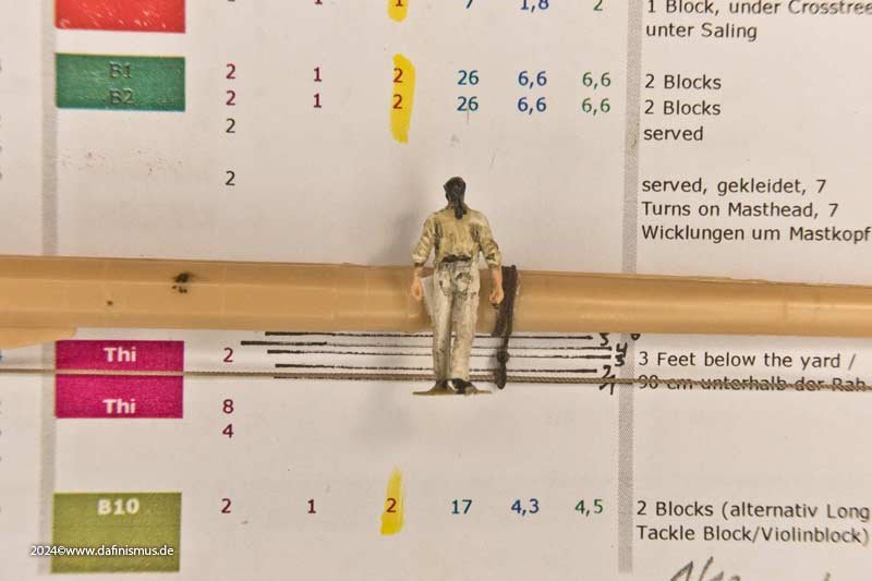
He is quite tall for the times with 1,80 cm being 71". XXXDAn
-
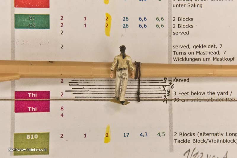
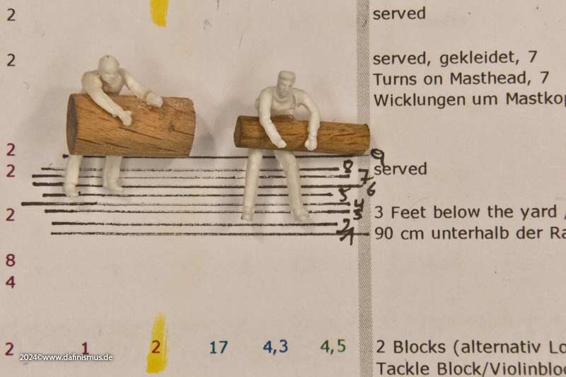
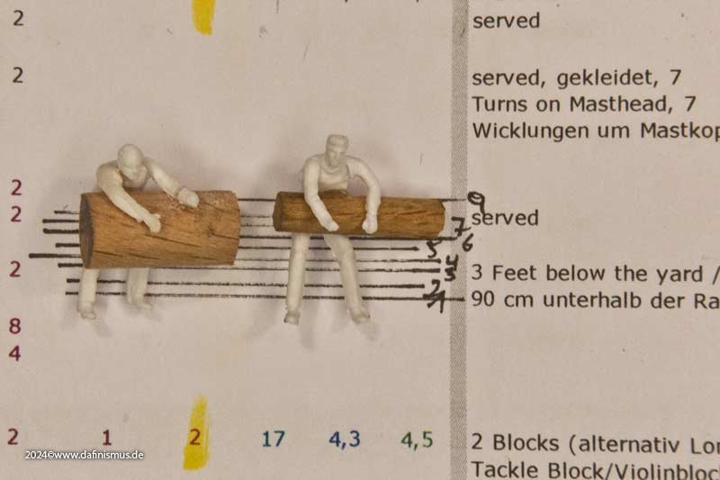
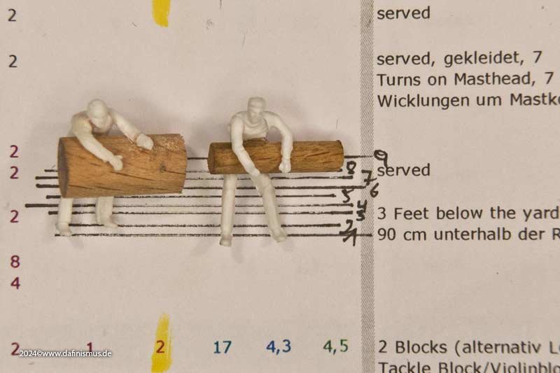
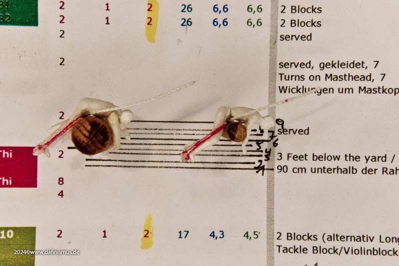
I was most surprised by the stirrups: 3 feet below the yard. When I held my scale seaman next to it, my suspicions were confirmed: damn deep ... ... I would have instinctively hung it 4 mm higher so that my little Able Seaman had a chance of getting over it. If you add up the 90 cm, the thickness of the yard is up to 60 cm, as in the case of the main yard. That's 150 cm, just under my chin. Then there is also the depth of the yard to consider, so that in addition to the 90 cm length under the yard, there is also approx. 0.5 x the diameter of the yard. Another escalating factor is that the horse can sag quite a bit in the middle between two stirrups. To be able to judge this better, I trained two Able Seamen, one for the thickest part of the big yard with a diameter of 60 cm and one for the yardarm with a diameter of 30 cm. First the variant with 3 feet under the yard. The sailor on the thick yard has very bad cards. The tar jacket on the thin end fits better. If I refer the 3 feet to the center of the yard, it's better. If you relate the 90 cm to the upper edge of the yard, it fits best. Here the sailor has the opportunity to use the horses at the thick point, the colleague on the outside still hangs at a similar height. To confirm this interpretation of Steel's specification I had a closer look from the side. The red part of the stirrups is about 3 Feet and it looks perfect both for the simply standing on it as for the working in a upswung position. If one takes the other descriptions the remarks to the simplyfied "3 feet underneath the yard" it would possibly read like this: Stirrup long 3 Feet, nailed to the top of the yard, with enough overlength to do 3 turns around the yard. Hangs behind and underneath the yard. Could this interpretation be correct? XXXDAn
-
For the blocks of my Victory I had to work my way through David Steel's The Art of Rigging. Originally, I had oriented myself on McKay's AOTS, but then realized that there was still a lot omitted and there were also some errors. Steel is much more detailed, but there are some ambiguities as well as differences to other sources. Here are a few that I am working on and wondering about 🙂
-
This is still the time of no uniform for the seaman 🙂 Preferred color blue and white, but not as uniform but as the purser usually bought larger stocks of cloth to be sold at the sailors and therefor som uniformity came into the game. But on the other hand plenty sailors wore their privat cloths, thus giving all shades of contemporary colors. Marines were more disciplined in that sense, sometimes were more regulated, as were the midshipman and officers. XXXDAn
-
Great work. Interestingly, when comparing McKay + Longridge with Steel, I noticed that Steel replaced most of the long tackles with normal double blocks. Only not those on the forestays, which are still listed there as with long tackles. I usually fix the fall with a half hitch between block and hook and, depending on the situation, either wrap the overlength in a bunch or wrap the rest around the fall, which I would do on the stays. XXXDAn
-
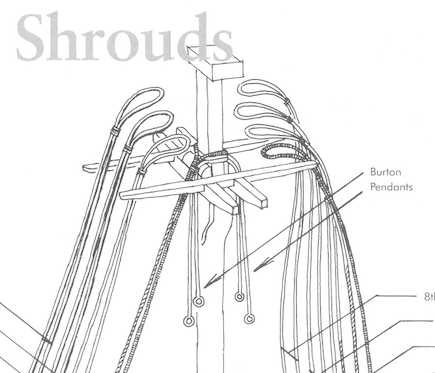
Hello William, congratulations for your persistence and the want to learn! If this is the mizzen mast the Slice is right, if this is the main or fore mast then the pendants should be looped over the masthead in a pair like the shrouds do. Here a cutout from Peterssen. As for the blocks, McKay apparently omitted them - as it was for many years on the V. in P. Steel is using Single 24 Inch for main and fore (15 and 36 in AOTS and the spreadsheet that I did send), and 11 inch for the mizzen. Also for Runner and fall that are hooked in there Steel uses normal single and double blocks, as for most of the literature there are long takle blocks mentionend. For your build there is a sprue in the standing rigging section called "Pendants of Tackles" 015-036with enough good blocks of the said size. Also the 11 inch for the mizzen and topmasts can be found there 🙂 I added a PDF with an overview which blocks to be found on what sprue, hope it helps. I did some more crosschecking on the matter of blocks and added some more blocks to fit for different rigging sources. All those that already did purchase blocks, there will be a new version of the spreadsheet and free "extension set" coming soon 🙂 XXXDAn Layouts Blockversand V3.pdf
-
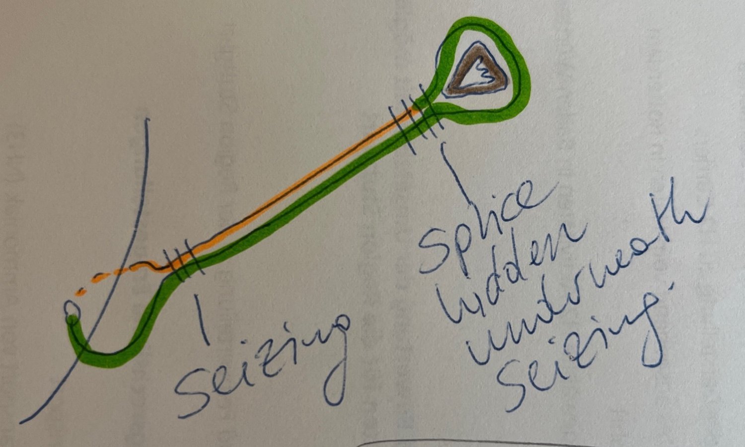
Laniard imho ok, but see my scribble for the rest. The joint of the ropes is hidden underneath the seizing. XXXDAn

-
Just a small warning for those who follow the sequences of my build: Please remember to put the shrouds before putting up the stays! My stays are up for test purposes, I will still have to reopen the lanyards take the stays off, fit pendents and shrouds and then finally reset the says and its lanyards 🙂 All the best, DAniel
-
Just a small warning: Before the main- and forestay can be set, do not forget to put up the shrouds! XXXDAn