
HOLIDAY DONATION DRIVE - SUPPORT MSW - DO YOUR PART TO KEEP THIS GREAT FORUM GOING! (89 donations so far out of 49,000 members - C'mon guys!)
×


dafi
-
Posts
2,426 -
Joined
-
Last visited
Content Type
Profiles
Forums
Gallery
Events
Everything posted by dafi
-
 In the meantime, the bow is paneled. After the "take photo without card lock" of the camera was turned off, I am missing the pictures of the open subconstruction ... First as usual the frame imitations inserted, then the whole thing was paneled. Since the anchor cable hatches are also misaligned, those were closed up right away as well. XXXDAn
- 58 replies
-
- 8
-

-
- Revell
- Constitution
- (and 1 more)
-
In order to get a little more structure into the few possible views into the lower deck, I have printed the characteristic triple knees of today's Constitution. Whether these were already in place in earlier eras of the ship or if they were only installed during later conversions is beyond my knowledge. I would have instinctively guessed the classic use of 3 separate knees for the early phase of the ship. I would be happy to take any hints on this. Due to the kit, I can't work with deck beams because the ship has to be pressed into shape by the upper deck. Therefore, I have to skip the upper part of the knees too. Placement check with guns. And in the end it's all about such a view anyway http://www.shipmodels.info/mws_forum/images/smilies/icon_smile.gif XXXDAn
- 58 replies
-
- 10
-
-
- Revell
- Constitution
- (and 1 more)
-
I do not see more problems coming. It even can happen, that the "inner planking" can deform the hull even more. But that has to be corrected with the upper deck used as stabilisation factor. XXXDAn
-
After all the battens were mounted, the cleaning up really started. Rough overhang was minimized with the scalpel, then the top and bottom were filed with the sandpaper battens as already described. I also made a small tool for the inner surfaces. For the bow area there was something more shorter and rounded. After everything was smooth enough we went to the spirketing. A 1 mm thick polysterol strip at the bottom, 0.5 mm Polsterol between the ports, and another 1 mm above that. And the fit sample. Fits http://www.shipmodels.info/mws_forum/images/smilies/icon_smile.gif To fit the lower strip, press it well inside ... ... on the outside, score the lower edge of the port with a scalpel ... ... make the scribe visible with paint, i.e. color it and wipe away the paint on the outside so that only the depth of the scribe remains colored ... ... and cut off the overhang based on these marks and glue this adap´ted stripe in. Between the ports, orient the 0.5mm strip to the height of the ports. If you have worked evenly when filing the ports should be always the same height. And the one side is ready. Now the other side and then the head area and the side galleries areas. XXXDAn
- 58 replies
-
- 9
-
-
- Revell
- Constitution
- (and 1 more)
-
I'll come back to the Battle Station later to still add some life. But it was time to do some stretching. First off, built a sturdy stand. Then came bondage. The hull is unfortunately so warped, that here rougher force in the form of tight lacing had been necessary. The lacing allowed me to spread the load better. Still, later the hull partially burst open again, so the rougher tools came into play. Result was that it finally lasted ... ... but as collateral damage the hull had become quite wavy. Later on, the insertion of the upper deck will be a even-ing challenge http://www.shipmodels.info/mws_forum/images/smilies/icon_wink.gif (Mark the bun!) The next step was to double up the ship's side. This makes the difference between the appearance as a classic plastic kit and upscale modeling appearance. Built up a small stop to do the doubling. Then glued inside 4 mm battens against the stop. Then inserted the sills at the top and bottom, making sure that there is enough overhang in each case. The space between these port frames was also filled with battens. If there is too much protrusion of the sills, this is first minimized them with a sharp tool. Then cut a flat batten to sand down the remaining overhang at the top/bottom, with minimal undersize in the sanding area and slightly more on the opposite side port. Taped 240 grit sandpaper to it with double sided tape, that fits well with my rather soft battens. The strip is passed through the port on the opposite side, this gives an even horizontal angle. Then sanded the sill on top ... ... turned the batten over and sanded the bottom sill. Prepared another sanding strip for the sides ... ... especially in the bow area at the idle ports, some rework is needed because of the strong bend. And this you get as comparison: original version Revell ... ... and the revised version http://www.shipmodels.info/mws_forum/images/smilies/icon_smile.gif XXXDAn
- 58 replies
-
- 10
-
-
- Revell
- Constitution
- (and 1 more)
-
The dimensions of the hammocks are well known. The diameter of the rolled sausage also can be seen in contemporary drawings. Even if they were sometimes thicker, because blankets were still rolled in, I choose the thinner version without additional content. Contemporary sources show 7 to 9 laces. Some say like the 7 oceans, on Bray's sketches you can see the variant with 9. The mats were rolled of Fimo, the laces rolled in by means of a special comb. Since the holders are very low, I first tried the straight variant. I found the bent variant better, as it is also historically documented in many cases. After that, a bit of 50 shades of beige , plus some ink for shadows and depth and the lacing in the visible area represented with thin yarn and it all fits so far for me. XXXDAn
- 58 replies
-
- 8
-
-

-
- Revell
- Constitution
- (and 1 more)
-
Then attached the hammock cranes with the netting. Mounted the white net in the cardboard frame and first primed it with white and then colored it slightly brown. Then inserted two strips of paper as a convenient insertion aid and inserted the net with a wooden core. Then on the outside, fixed the net with super glue at points, widened the core so that the net fits well on the inside of the holders, and also fixed the back side of the net at points. Then removed the core, glued the net well to the top rope and trimmed everything well with the pointed scissors. After that, some more trimming was done and next comes the hammocks. XXXDAn
- 58 replies
-
- 9
-
-
-
- Revell
- Constitution
- (and 1 more)
-
In addition to the figurehead of the Victory, I also made some progress with the battle station of the Constitution. First attached the eyebolts for the carronade's gun rig. To determine the length of the tackles I again documented the different positions. In the last two pictures, it can be seen that the hooks for the tackles are too close to each other to work effectively because the angle is too tight. That's why two more eyebolts are needed further out. While this position is technically possible, I think it is a special case that can be well achieved with handspikes if needed. To tie the breechline, I built a small rigging aid. Hammered in two nails spaced at width of the eyebolts and fixed the carronade in maximum aft position. Then tied the two rope eyes, nice and tight around the nails. After tying the eye, just pulled them out over the top of the nail, bent the rings up from the eyebolts on the bulwark, removed them, slid them through the eye of the rope, bent them closed again a bit, and reattached them to the bulwark in the eyebolt. Looks like this then http://www.shipmodels.info/mws_forum/images/smilies/icon_smile.gif XXXDAn
- 58 replies
-
- 6
-
-
-
- Revell
- Constitution
- (and 1 more)
-
Thank you all for the nice words! After the stressful pre-Christmas period, I actually managed to leave the computer on the side for almost 3 weeks. At least I just managed to finish the programming of the 1803 figurehead of the Victory Now here is the addendum from Käpt dafi, who was really looking forward to the painting. Attached are the parts as they came out of the printer. The motto "Honi soit ..." is already imprinted, but with the etched parts it comes a bit more concise, so scratch out one letter at a time, with a thin wooden stick ... ... set some not immediately setting superglue to the respective place ... ... using another stick to move the letter to the right place ... ... ... and with a thicker chopstick pressed the letter to the curve by tilting it in and out. Here's one with the letters imprinted ... ... and once with etched parts glued on. The back also finally has volume and sits neatly on the head. And for the sake of completeness here the comparison to Heller's original part, the painted one finally slightly inked to get the necessary depth. Dear greetings and a happy new year to you all, Daniel
-
And seen from deck´s height it would look like this ... ... scnr 😉 XXXDAn
- 58 replies
-
- 5
-
-
- Revell
- Constitution
- (and 1 more)
-
In between all the X-Mess preparations, I actually managed to get down to business again http://www.shipmodels.info/mws_forum/images/smilies/icon_smile.gif Status: First it was about taking the measurements. That means at the back the blocks must not overlap ... ... and the front position determines the length of the lanyard And always the anxious question about the side rigging. After the shot in the retracted position and enough rope for 3 to 5 men to pull, yes there is quite a bit of rope left when the piece is run out again. But if no one pulls the ropes, it isd mostely displayed directly as running into coils lying on the deck. That has two flaws: First, so the gun can move by itself and slide inward. In addition, the rope is shown mostly in a stretched position that would never be able to run smoothly into the coils, as it obeys gravity that pulls it. So if no sailor is at hand and secures the free ends, the rope should be secured to the gun, the tackle or the ship's side. On my Vic I had made a half hitch around the aft end of the side tackles, Boudriot shows the "amarage simple" around the cascable. The first attempt went wrong, as at Boudriot there was no splice over the cascable as the breechline goes through the gun carriage, and there it worked well. After some research I found a reference, where the lanyard was led under the eye splice of the breech. So the free end around the cascable, some turns as required ... as ... and the rest as a bunch neatly arranged on one of the hooks. So everything should be neatly tidied up and secured. XXXDAn
- 58 replies
-
- 6
-
-
- Revell
- Constitution
- (and 1 more)
-
Until now, the bottleneck in rigging the guns were the blocks: There were almost no small ones, and if there were, they were often difficult in appearance or quality. Recently, I have test rigged my smallest self-printed blocks times and noticed that fine thin and steady surgeon hands are needed, including good visual reinforcements. And I realized that suddenly it is now me beeing the bottleneck ... Here the measure of things was the thinnest rope I needed in 1:100, 0.2 mm diameter. Something for the filigran ones among us http://www.shipmodels.info/mws_forum/images/smilies/icon_smile.gif Now the pragmatist in me came out again. According to the old literature I need for the guns in 1:100 / 1:98 the diameter off 0,3- 0,4 mm for the ropes for the lanjards of the side- and back tackles. The 0.4 mm rope is also a common thickness for Gondesen and other suppliers in the aftermarket. So a block combination on this rope thickness is required, and also a good method in which this is done quickly and with good visual results. It has cost me a few attempts, meanwhile I have found the right variant for myself. First a normal classical knot to tie the hook in ... ... then the whole thing tightened to the back, in order to make the hook sit well in the middle ... ... spreading the ends again and ... ... put the block of choice ready. Then clamped the hook between my fingers, used a toothpick to make a drop of super glue in the middle on the knot of the hook and centered the block on it. Don't let go of the hook now, but detached it would look like this. This is just the positioning guide to superglue the groove on the side with the toothpick on one side and pull the rope well over it. Do not grab the glued area, but pull on the free end. This works quite well without the whole thing forming an inseparable bond with the builder. Then glue the groove on the other side, pull the rope over it accordingly and make sure that the pull is even and the hook hangs centrally over the block. Then glue the bottom of the block with the toothpick and pull the ends against each other, cut off the excess diagonally, and press the two slanted ends against each other with tweezers or pliers, securing again with glue if necessary. And then you already have it in your hand, the rigged double block http://www.shipmodels.info/mws_forum/images/smilies/icon_smile.gif If you want you can strop the bridge between hook block a little bit, but I noticed that it doesn't help that much, so I made it easy for myself here. By the way, here is my first attempt, you can still see it somehow crooked, and the one after that, you can see, practice makes perfect http://www.shipmodels.info/mws_forum/images/smilies/icon_wink.gif With the single block it is the same, thread hook on the rope, knot, pull back, spread, hook between the fingers, glue in the middle, block on it to secure, glue the side and pull rope over it, glue the other side and pull over it, and now the difference, on the bottom a knot and secured with glue. Then the free end stropped up, glued and cut tight ... ... and the pair of block is ready http://www.shipmodels.info/mws_forum/images/smilies/icon_smile.gif And the other two pairs came together quite quickly, so I soon had a set of three ready for my gun setup. And as I said, no other tools or jigs were needed than a toothpick as a super glue applicator, I only used a pair of self-clamping tweezers on my bench vice to srop on the free end of the single block. All the best, DAniel
- 58 replies
-
- 8
-
-
-
- Revell
- Constitution
- (and 1 more)
-
Finally after a long time remounted my rope walk again. For space reasons simply hung in the basement hallway under the ceiling :-) Then I started rigging to try out the blocks. In the contemporary plans, the blocks are about half the width of the forward wheel. These blocks are minimally larger, which makes handling much easier. To do this, nailed a mounting hook into a piece of wood for holding the hooks. And for that the small blocks do not go off, I always put them immediately on the leash 🙂 And here the rigged hook and block from close up. For comparison in size ... ... and in place. Since I had pulled down one of the knees with my thick sausage fingers, I immediately took the chance to be able to photograph undisturbed 🙂 Greetings, Daniel
- 58 replies
-
- 5
-
-
-
- Revell
- Constitution
- (and 1 more)
-
I continued a bit over the weekend. First fixed the bolts and rings in the hull ... Then prepared the breech: 0.6 mm, the middle marked by means of black thread. The barrels had no brech ring on the pommelion, so the breech needs an eye splice to prevent it from slipping off. The small parallel piece is glued on first. So that the attachment is not too obvious, it is cut off at an pointed angle ... ... and glued on. Then came a test fit to determine the length. Stabilized the cut with super glue ... ... glued on ... ... and fits http://www.shipmodels.info/mws_forum/images/smilies/icon_smile.gif A good model building solution in itself, ... ... but in the original, this splice was additionally dressed to protect against the large stress when guns were fired. Then made a template for the length of the breechline. The eyes are bound in the manner of the dead eyes. And everything is ready for installation ... ... and in place. Here in the loading position at the very back, the brooktau tensioned. And run out here. So slowly it's moving in the right direction. XXXDAn
- 58 replies
-
- 5
-
-
- Revell
- Constitution
- (and 1 more)
-
Seats of Ease
dafi replied to stuglo's topic in Discussion for a Ship's Deck Furniture, Guns, boats and other Fittings
Oh my favourite topic 🙂 I am having a good collection of the topic at https://www.segelschiffsmodellbau.com/t866f104-The-Heads.html One can activate the automatic translater if you scroll down the page and on the bottom you will find a button with "Sprache auswählen". Change this to english or the language that you prefer 🙂 Especially I like the contempoary grafics and paintings, even two lads doing business in the middle of a raging battle ... :-0 XXXDAn -
Carriage Gun Rigging
dafi replied to Dr PR's topic in Discussion for a Ship's Deck Furniture, Guns, boats and other Fittings
Just realised, that todays Constitution has cablets as breeching lines. Surprising, as they are meant to be more stiff than normal right handed lay, therfor more danger of breaking under the violent bent at the breech. Par opposite the Victory has (or at least had for a long time) lefthanded breeching lines, probabely as they are more flexible, means less breakable and also better absorbing the shocks. Any Idea of that? XXXDAn -
Carriage Gun Rigging
dafi replied to Dr PR's topic in Discussion for a Ship's Deck Furniture, Guns, boats and other Fittings
Just realised on a picture I posted in the Gibraltar thread, that there too were double blocks hooked in the back of the carriage. Here clearly the standing part comes from the other hook. More intriguing in your picture is the use of a cablet as breeching line.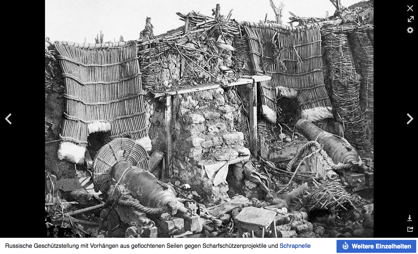
-
I got mail today, fresh off the press, from Kerry Jang in Canada: Victory, 100-gun First Rtae 1765, Seaforth Publishing. The book is part of a series ShipCraft and is number 29. The book deals with Victory model kits and is aimed specifically at modelers. Besides history, it presents the available kits from 1:1200 to 1:64 in the full range of materials, gives an overview of the current aftermarket and presents 3 built models. A larger article goes over the various appearances of the ship and ends in new overview drawings, done especially for this book by McKay. I have yet to analyze the historical and appearance part at times, but know that Kerry Jang has talked to a great many protagonists of the Victory scene. Personal notes: - McKay´s AOTS was my first stop on the way to Victory. The color on the book´s pages were watched pale ever since. - I stood in front of the first of the 3 models presented in the book at the convention in Rochefort with my mouth open, jaw to the floor: the 1:300 version by Etsuro Tsuboi. Breathtaking! - The second model of the Victory is 1:48 by Kazunobu Shirai and it was the first model of this ship that I fell in love with over 15 years ago when I started doing internet research on this ship. - And the third model shown is actually the little fatty one with bumble bee stripes by a certain dafi :-0 Never, really never would I have dared to dream of ending up with 3 of my heroes in the same book! Thank you Kerry for that opportunity! Dear greetings, DAniel
-
Dear Bill, it is a great honor and splendid pleasure to be quoted by you in such a wonderful display with this wonderful rendition of this iconic ship! It had become an icon in its own sense. Wonderful model making, and congratulations, far too many good model makers never brought it that far in that perfection! All the best, DAniel
-
And I was finally able to do some more woodwork. Got the lathe out and turned some supports. Then built the 4 knees. And suddenly the part flew towards the aspiration tube. THAT'S WHY I have the perforated metal grating there on the smoke http://www.shipmodels.info/mws_forum/images/smilies/icon_smile.gif Fitting ... ... and ready. Here you can see the two diagonal knees above the gun. And so that I don't mess up when rigging the gun tackles, I made the upper deck removable. Now it's going to be small itsbits, looking forward to it, XXXDAn
- 58 replies
-
- 7
-
-
- Revell
- Constitution
- (and 1 more)
-
Carriage Gun Rigging
dafi replied to Dr PR's topic in Discussion for a Ship's Deck Furniture, Guns, boats and other Fittings
The interesting thing is, that the carriage is exactely identical with the drawing from Mr. Rivers sketchbook and showing Victory´s carriage. XXXDAn -
Possibly something alike like this russian position at the Crimian War. Shelter against sharp shooters and shrapnels. XXXDAn
-
There are several contemporary models showing this feature in the NMM archives. Many of them still have a large compass rose in the middle. If I remember well, there is already a thread here in MSW showing those. https://collections.rmg.co.uk/collections/objects/549999.html SLR0506.3; 'Superb' (1760) Date made circa 1760 Also a nice detail about Nelson, reported by his secretairy: As he did not want help to dress and undress as for his missing arm, he always wore loafers even at heavy weather. So he was able to dress and undress them by himself and if his feet got wet he used to walk in socks over the carpets in his cabin, until the feet got dry 🙂 This means, it was not unusual to put something over the chequers still. XXXDAn
-
Carriage Gun Rigging
dafi replied to Dr PR's topic in Discussion for a Ship's Deck Furniture, Guns, boats and other Fittings
As this topic came up newly, I can add some better pictures of Thorsminde, taken this summer :-) Fascinating to see the 1812 mounts. A total of 3 are on display in 2 rooms. I had to climb a little behind the display, but fortunately no one complained 🙂 You can see the mounting holes of the cheeks in the front and on the side. In the last picture you can see a label on the axle. I also never noticed the doubling up under the axle, possibly to serve as a slide if a wheel is damaged in action. In another room is another carriage. What is fascinating here is that two layers of paint seem to have survived: Ochre over red. You can see the play of colours here. Red and ochre paint? More difficult to see, the inscription of the rear end, to be read from the left: St. George
