HOLIDAY DONATION DRIVE - SUPPORT MSW - DO YOUR PART TO KEEP THIS GREAT FORUM GOING! (Only 24 donations so far out of 49,000 members - C'mon guys!)
×

ken3335
-
Posts
314 -
Joined
-
Last visited
Content Type
Profiles
Forums
Gallery
Events
Everything posted by ken3335
-
 Hi Mark, No that's how I got mine, I think that it's an older version. I think that I prefer it this way as all the cuts are then from the plan and any errors are mine. Ken
 -
Hi All, After screwing down the transom and re jigging the castings I found that what Pete has mentioned was correct. Everything now falls into place, all the castings fit perfectly and there is no need for cutting anything away and wow they look good. This part has got me quite excited now, can't wait to see it completed. Ken
- 424 replies
-
- 11
-

-
Hi Pete, Thanks for that. As I said after seeing the facia in place my initial idea didn't look as if it would be ok, so as I thought back to the drawing board. Ken
-
Hi, I've just screwed the facia on and I'm having second thoughts about recessing all but the upper windows, so before I cut anything away have you any thoughts that might help me on this phase please. Ken
-
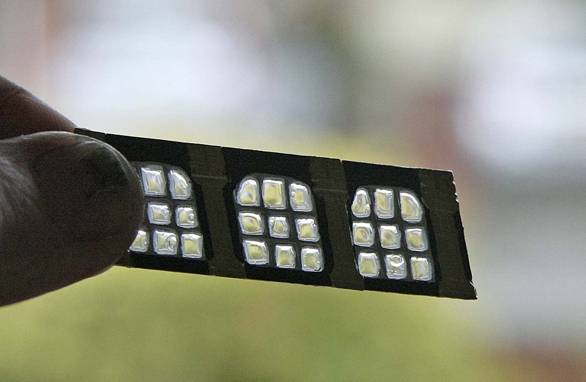
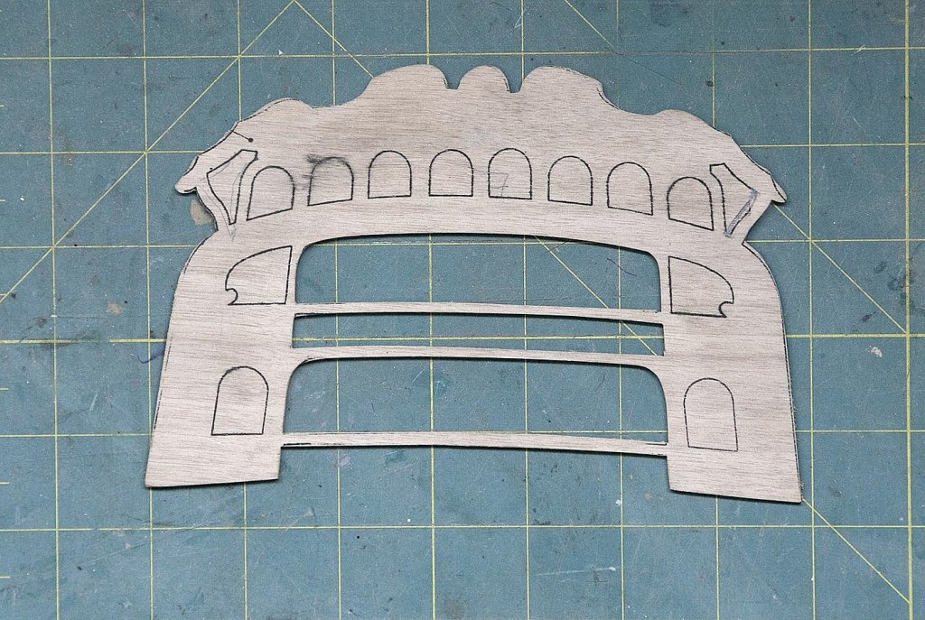
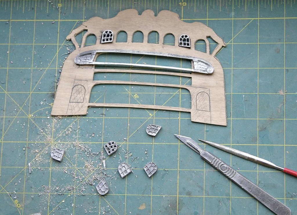
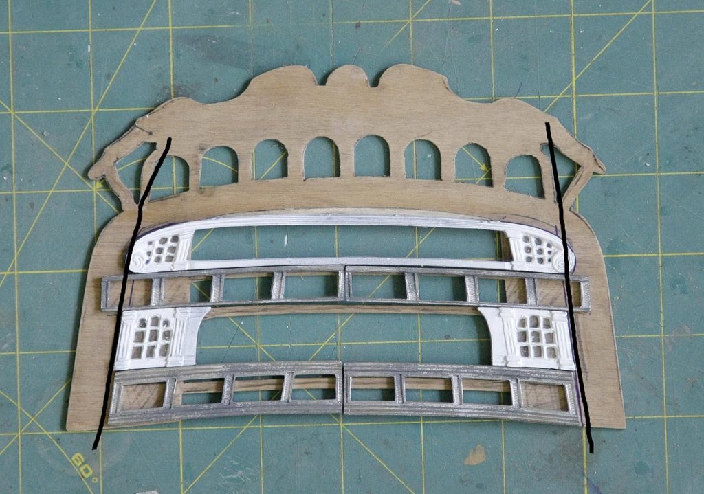
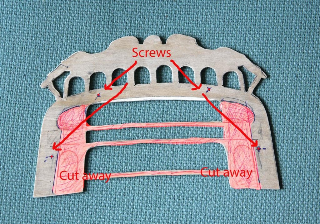
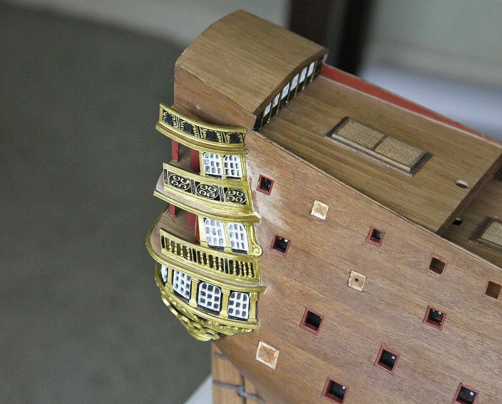
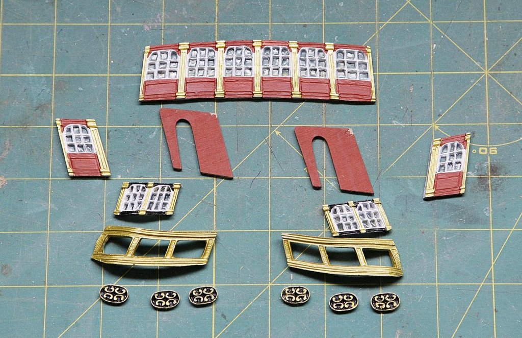
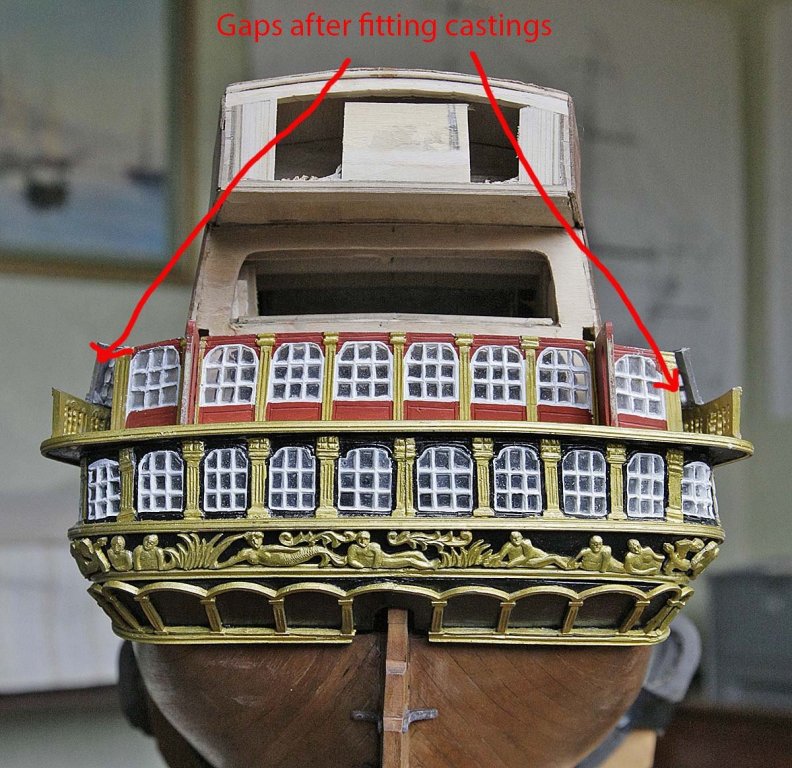
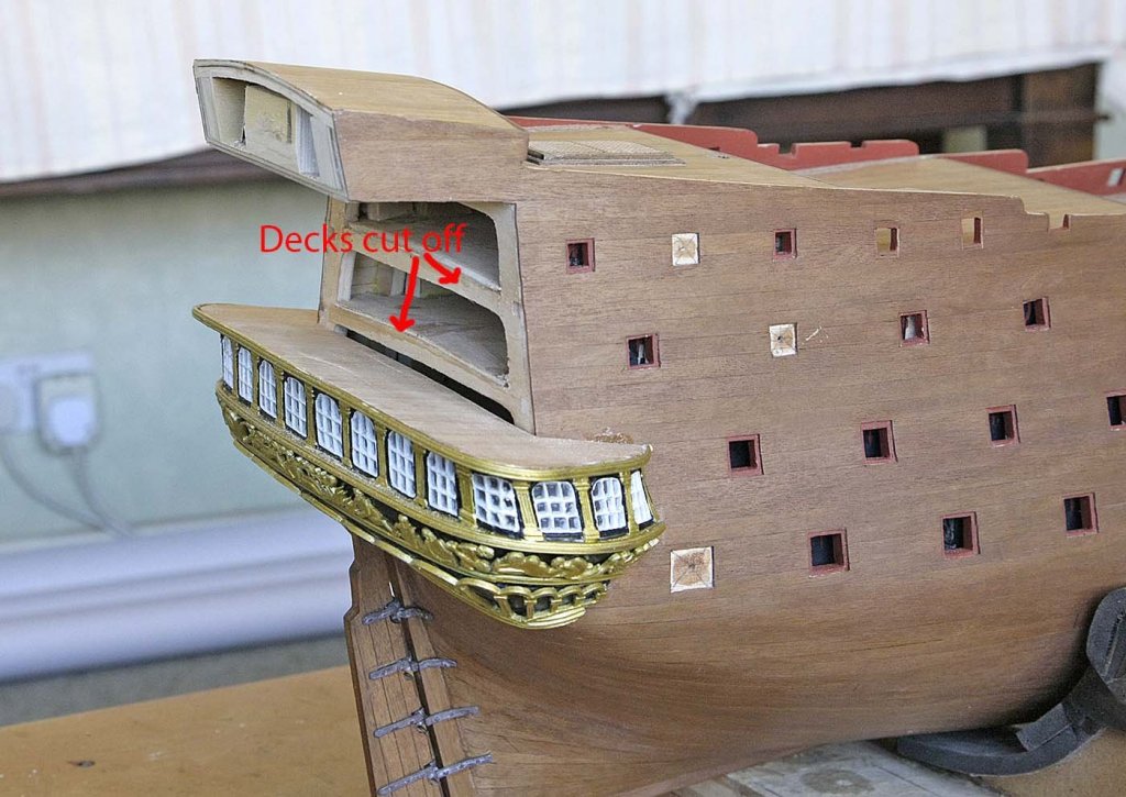
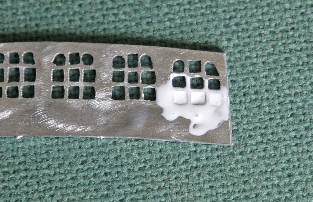
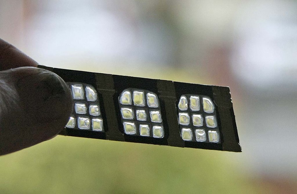
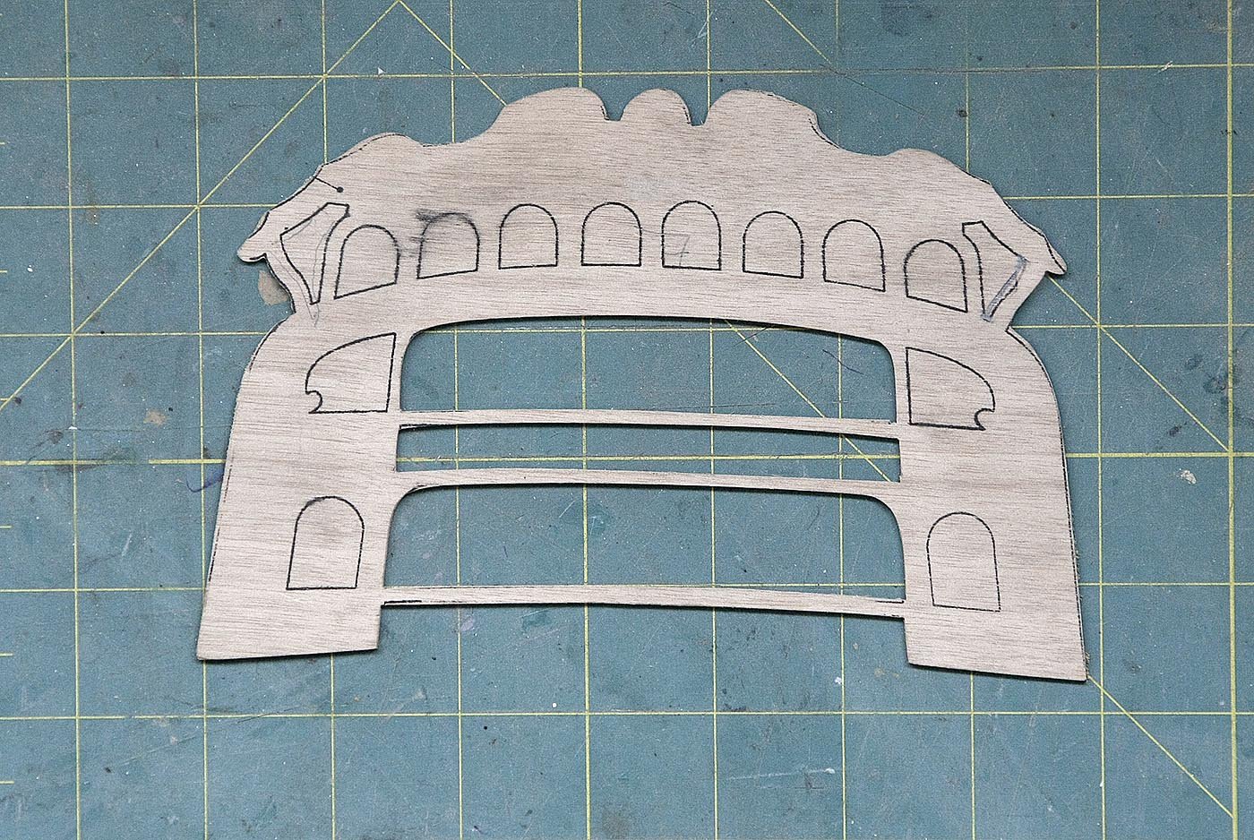
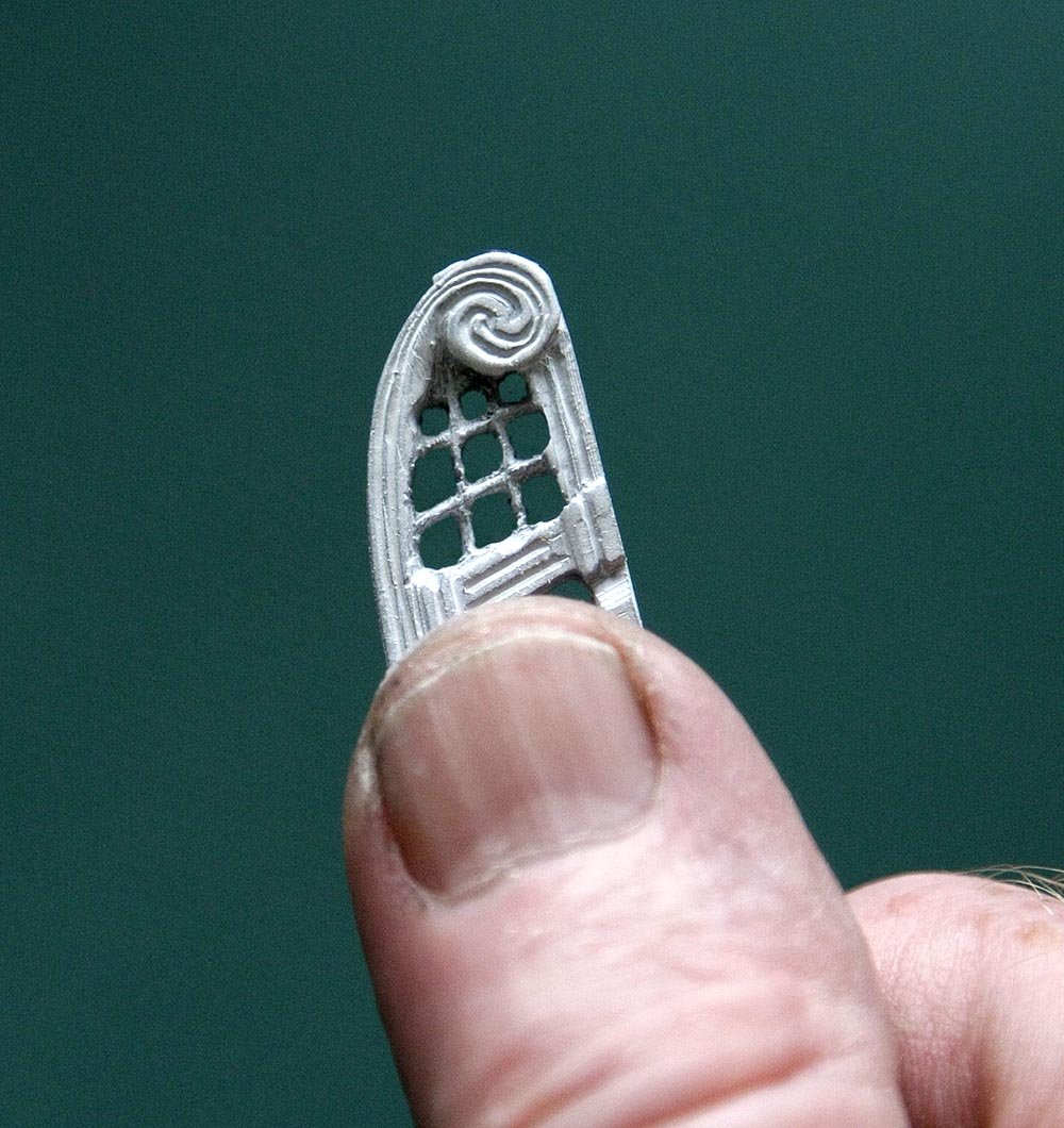
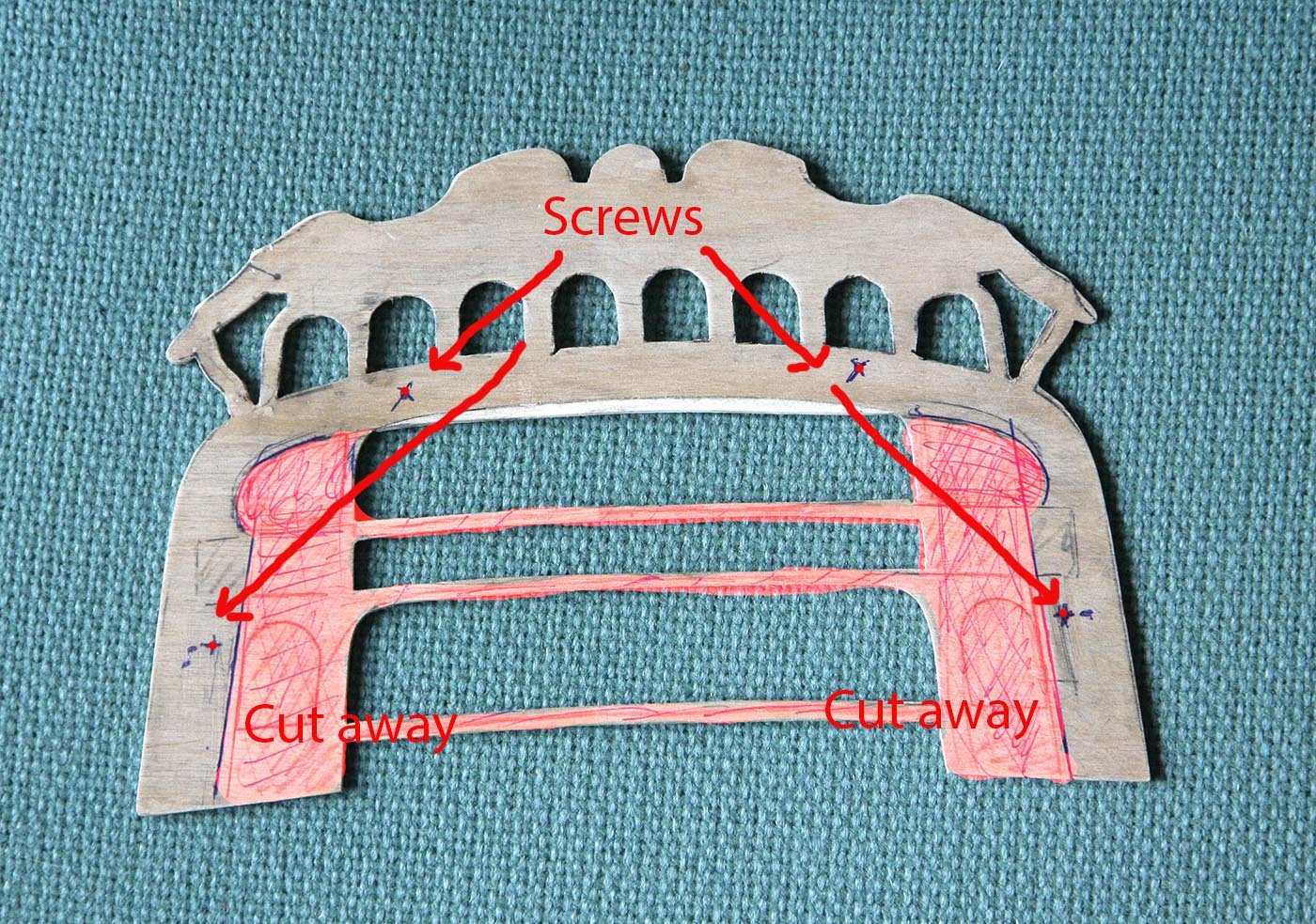
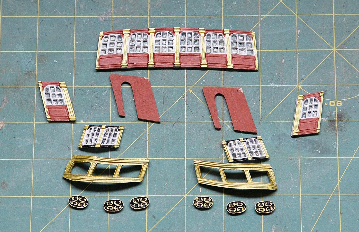
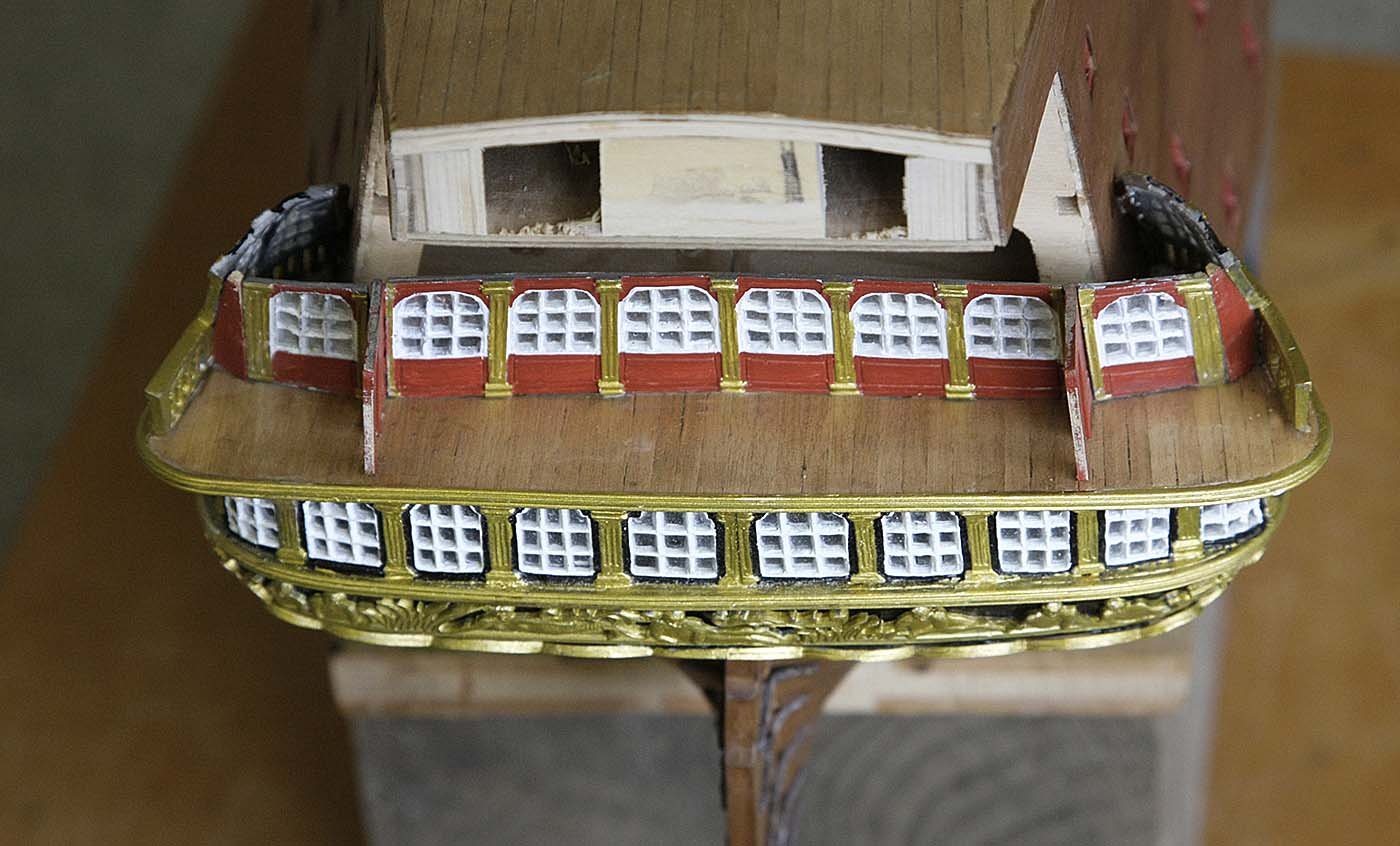
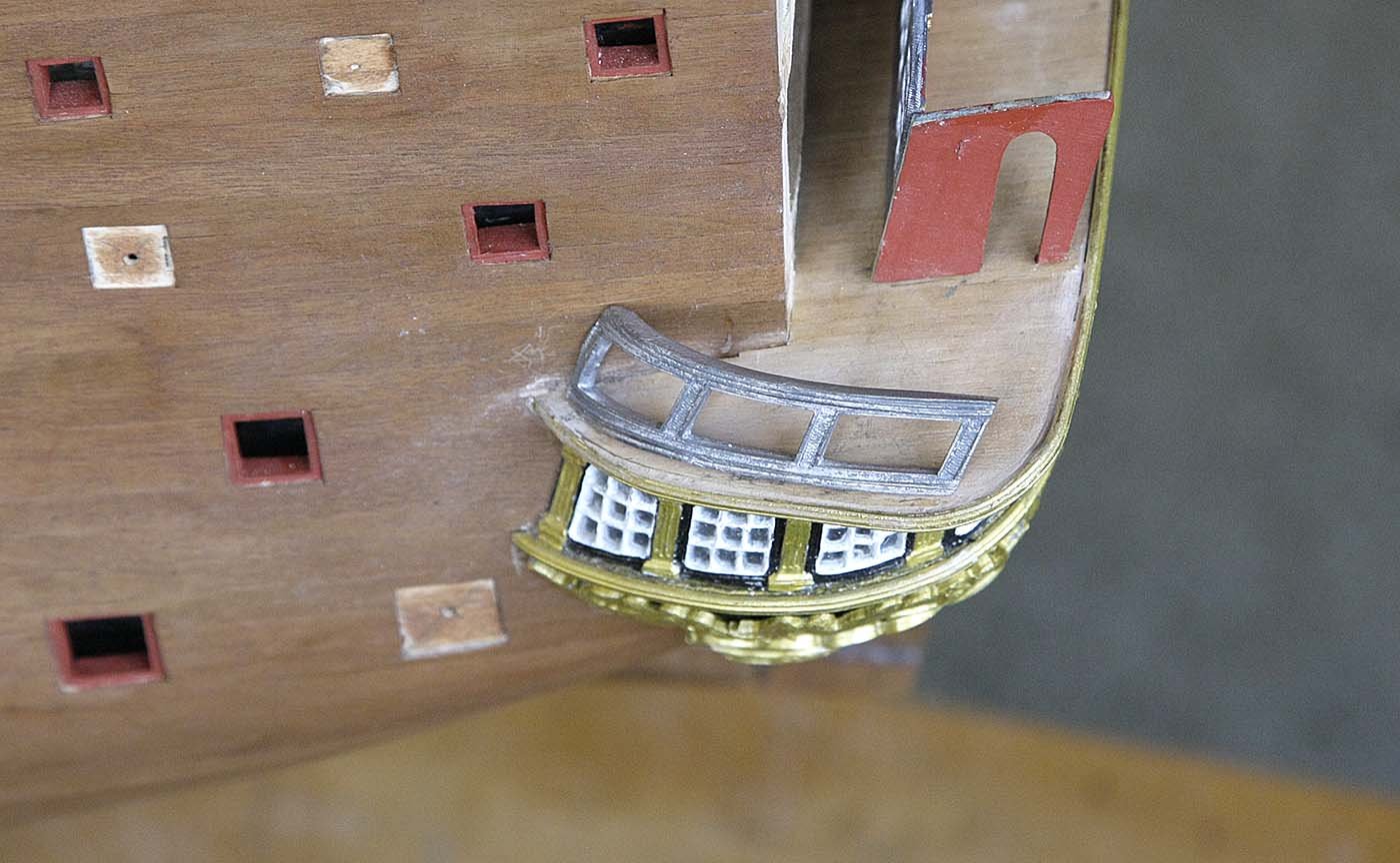
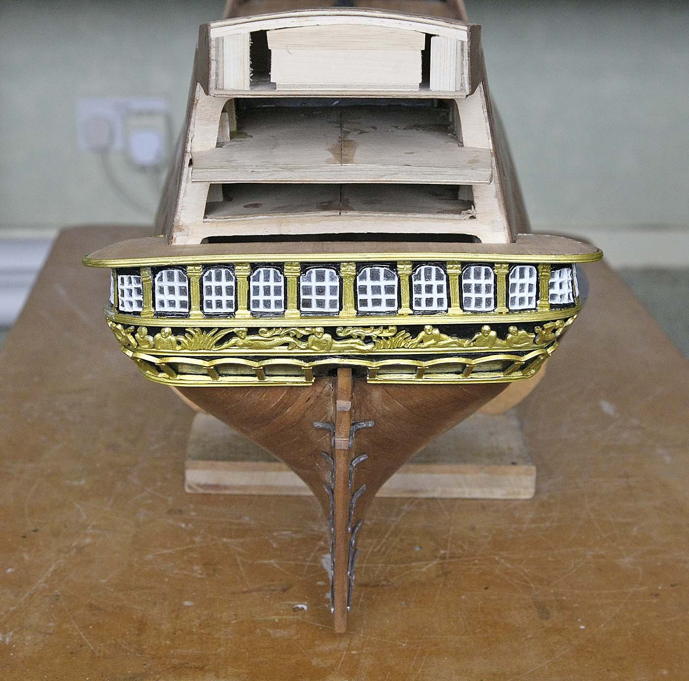
Hello Everyone, The build continues, probably the headaches to. I have found very little about building the stern transom, mainly just pictures of the end result so I feel a bit unsure of the approach. Some of the castings don't match up to what I'm seeing and I think that I need to cut away a substantial part of the supplied ply part. But here goes. I have now turned my attention to the stern transom. First I copied the stern facia from the plan and transferred it to the ply part supplied, there was some adjustment needed there but not too much. I sorted out the cast parts needed and loosely tried them for fit, I saw that it would not be just a straightforward attachment but needed some thought. I decided to recess the windows into the facia so my first task was to cut out the openings, the outlines for these openings matched perfectly with the castings and no further adjustment was needed. I hadn't intended to open the windows in these castings as the pane areas was so small I wouldn't be able to get a file into the space but thinking that with the other windows glazed they would look out of place just painted so I once again got stuck in. I drilled a pilot hole and using a narrow scalpel I picked out the panes bit by bit. I've shown a picture using my thumb for scale to show just how small these windows are. Once all the windows were done and loosely placed I checked the position of the balustrades, as you can see the supplied middle one appears to be wrong. I have shown the line that I think it should fit in with, not sure how to adjust it and still keep the eight inserts supplied and shown on the plan. At the moment I intend to recess the lower windows and balustrades so will need to cut away large areas of the facia to accommodate this, The shaded red area in the picture shows my intention. I've realized that this facia with all the castings is going to be some weight and that attaching it with just glue isn't a safe option so I'm going to use four small brass screws that the castings will hide to fix it in place, I've epoxied the blocks into place underneath the deck, I don't think that they'll be noticed. Ken


-
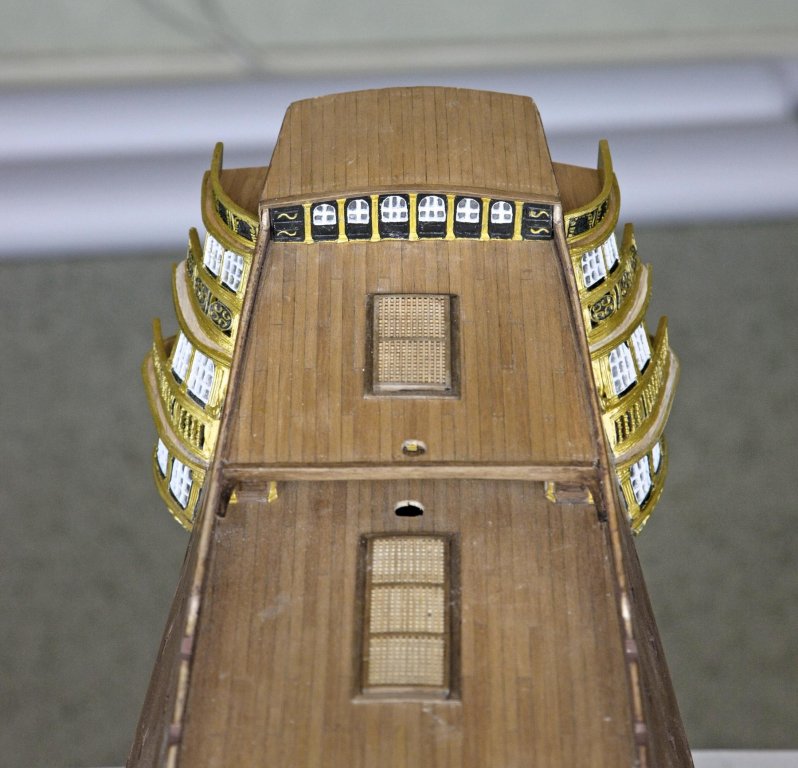
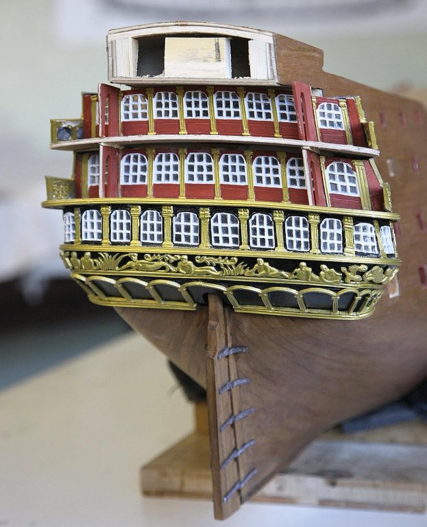
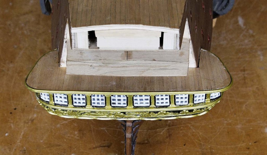
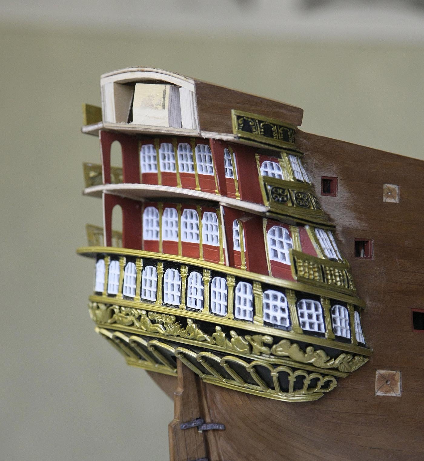
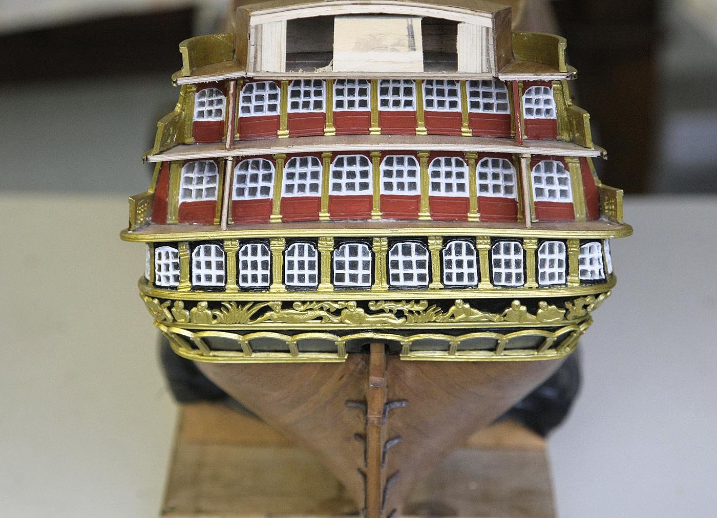
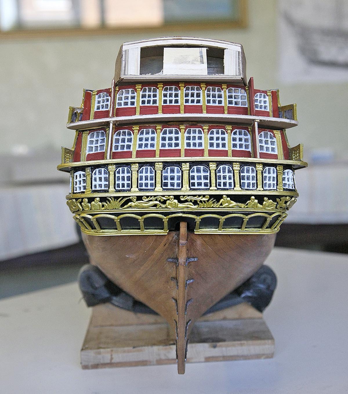
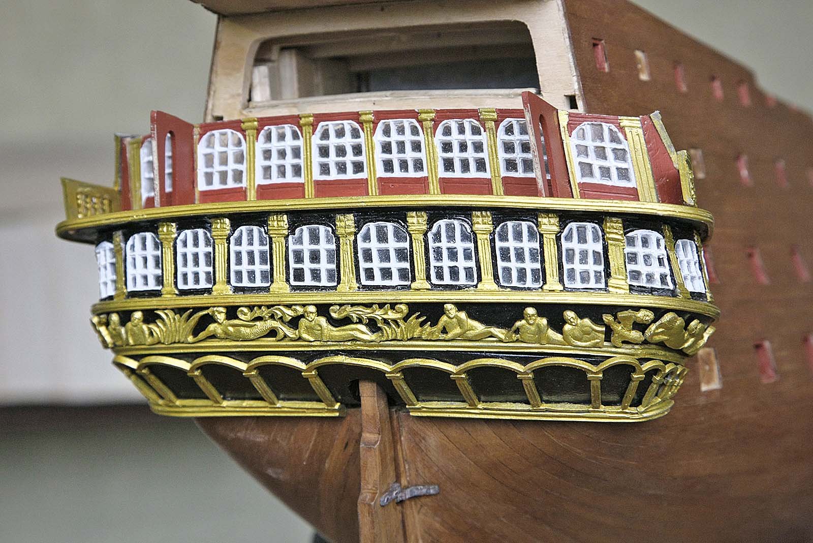
Hello again, Here's my progress report. The re-building of the galleries has now been completed as you will see in the photos. I only needed to take apart one complete gallery level and deck to make the corrections needed to bring things back into line, so not too bad. The mistakes that I'd made were that I had made the deck with a slight overhang of the windows below and put the next level too near the edge of that deck thus leaving them too far out from the hull side. As I had done earlier I filled the gap to the middle windows, it had worked well on the lower galleries and seemed an easy option and looked ok. I had not considered that whilst at this stage it looked ok as the build got higher and the galleries became smaller this extra width that I'd introduced made the curves at the top needing to be extreme to fit and you saw the result. I made decks that fitted exactly above the windows and started the next level of the tier about 4mm in from the edge, the curve of the balustrade needed was less which made things easier and resulted in the inner and outer windows coming together as they should, no need for inserts. Confirming this was the fact that when I got to it the top deck the kit pre-cut part for it fitted and was used. I fitted a small strip of wood as edge casting around the top of the windows to give them a finished look. Oh for hindsight, having made up these gallery parts once I think that I would find no problems if I were to do it again knowing that the parts DO fit with only small adjustments. The difficulty is understanding the relationship between all the different parts, next to, above and bellow. Quite a bit of re touching of the area that I had worked on needed to be done, that really was the only downside. I'm now ready to do the rear facia with all of its gorgeous castings. ken

- 424 replies
-
- 10
-
-
Hello Everyone, As you may imagine work is now in progress so it may be a short while before there is anything interesting to report, so in the meantime here's another picture of a tall ship entering the Mersey. I'm sorry I don't know the name of this ship. Ken

-
Hi Mark, Thanks, now why didn't I think of that ! I'm ok in my mind with this as I've discovered how I went wrong and can rectify it with needing to remove just one level of the gallery. Ken
-
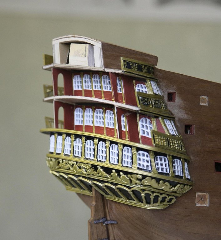
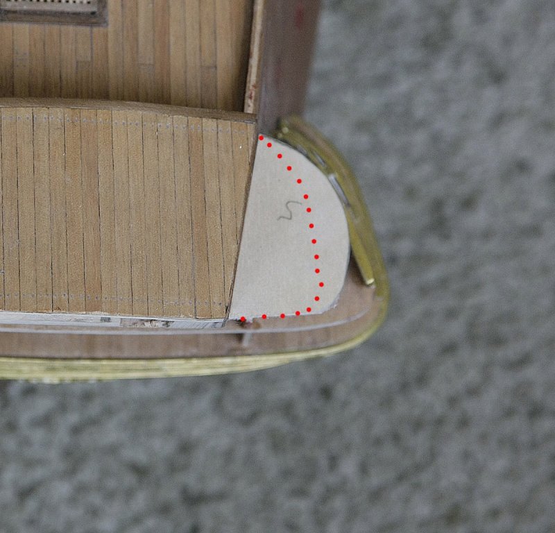
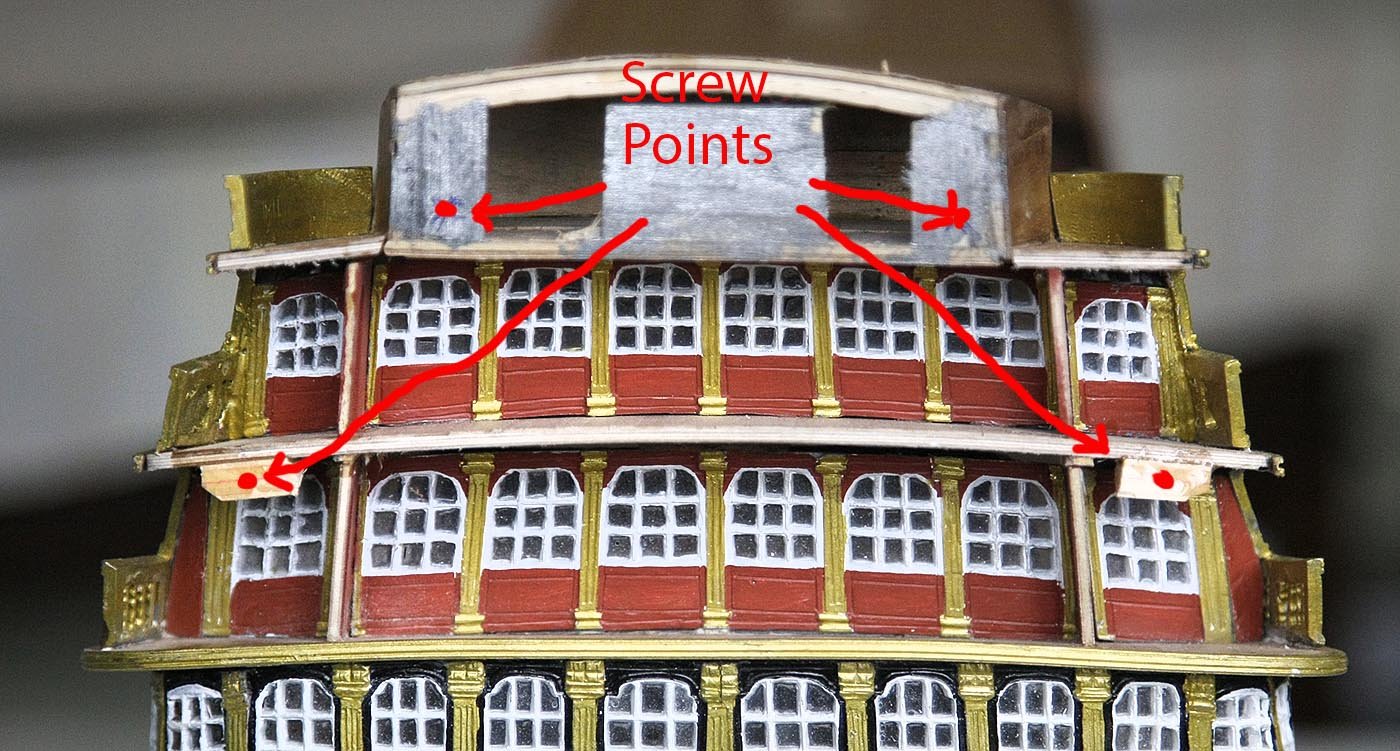
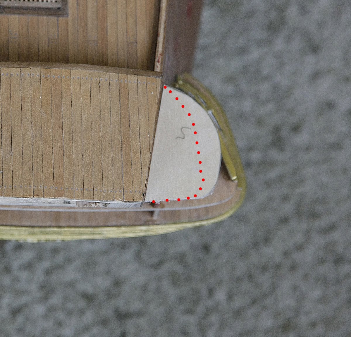
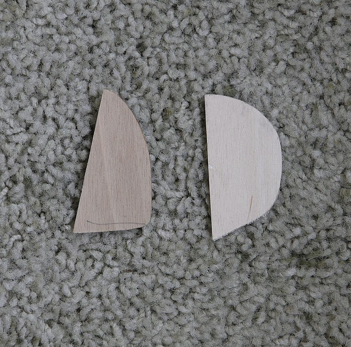
Hello Everyone, This post should be about progress that I'm making but alas I've taken another step backwards and am now recovering from my earlier errors, You will recall that on my second and third transom deck levels I used fill in pieces to make up gaps between the inner and edge castings and that the sizing fault was uniform. I said that as long as it looked ok I could live with it, well I'm afraid that I now can't. True to form the top tier was again too wide and this time there was no acceptable way of muddling through as this deck was open and in full view. To fit the top deck on the upper windows and not have there top edges showing it had to be so wide that the curve needed for it to line up with the rear transom facia looked so obviously wrong that something had to be done. I left it for a bit and had a beer not wanting to face the only choice I had and that was to start pulling the transom apart and now knowing how it should look re-build it correctly. I've shown pictures of the top deck how it would end up if I didn't redo it, the red dots show the size and shape that it should be, the other picture shows my deck against the one supplied in the kit, you can see the difference. So that I didn't chicken out I've just torn off the complete last level of the transom. Oh the joys of modelling. Ken
-
Hello Everyone, My latest progress report reads almost the same as my last one except one deck higher on the gallery. I had the same issue with the fit and the solution of the extra piece of facia was employed again, at least it is consistent. I must have gone wrong somewhere early on as the error is running the same for the whole height of the galleries. Unless I run into serious fitting problems later I don't see this as an issue as it looks ok to me and unless you are very familiar with it or compare it closely with the plan it isn't going to be noticed. Ken.


- 424 replies
-
- 11
-
-
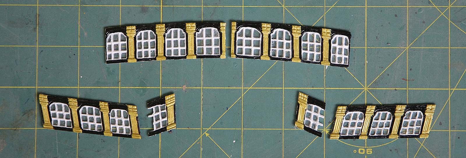
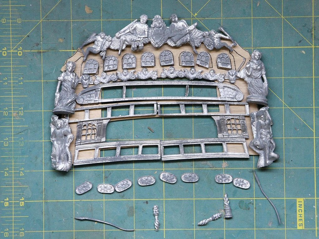
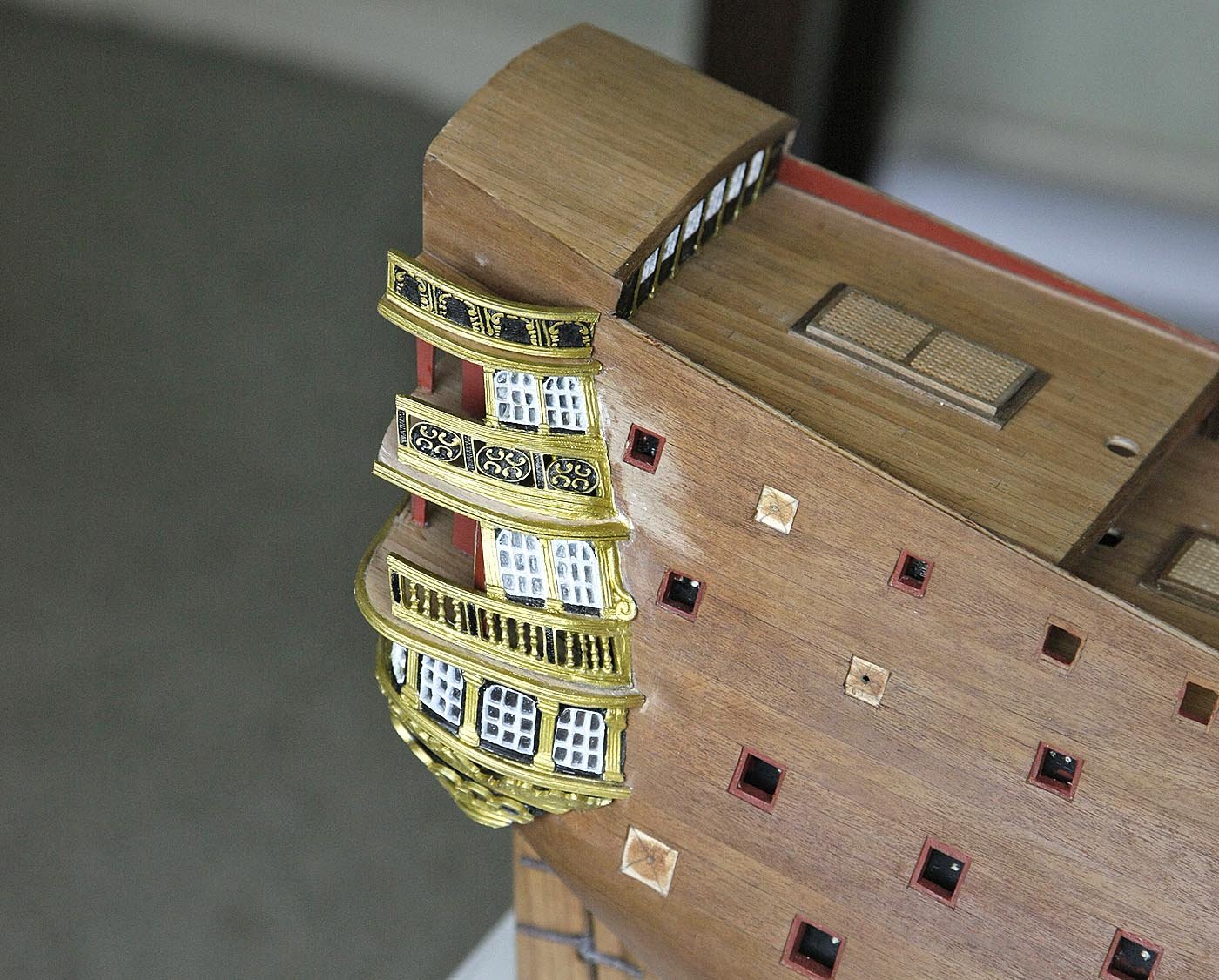
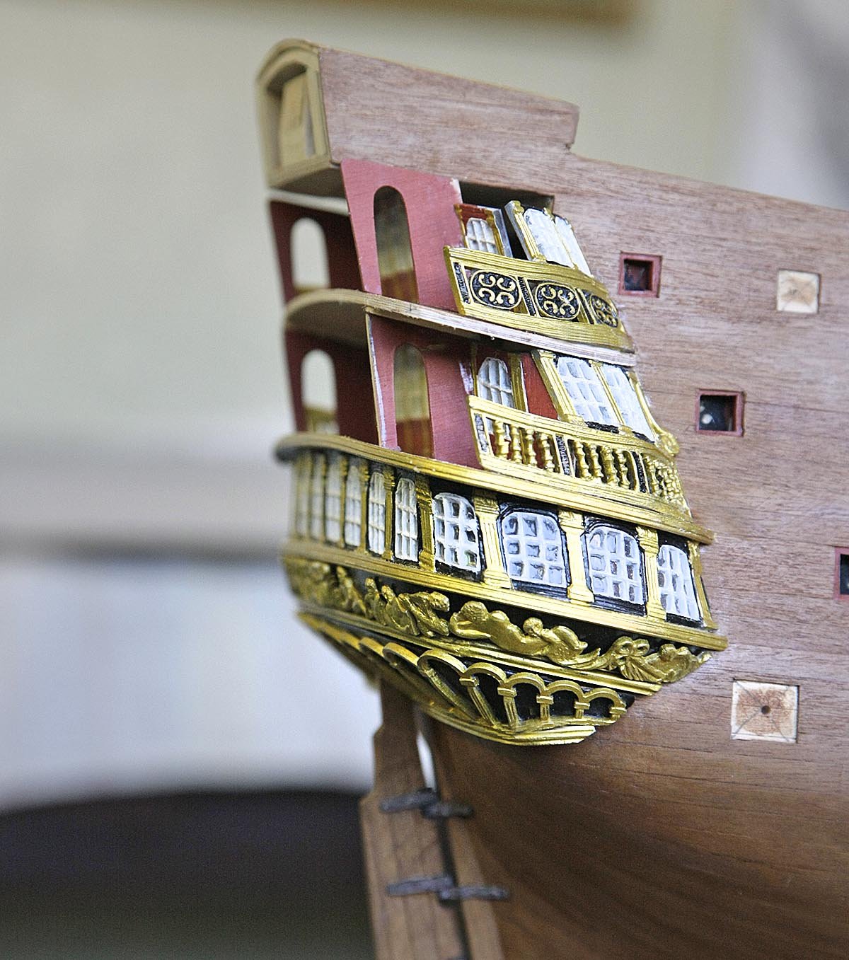
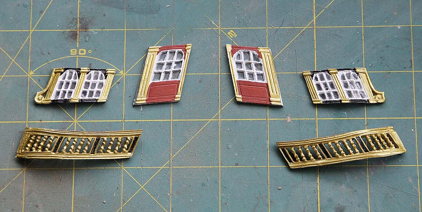
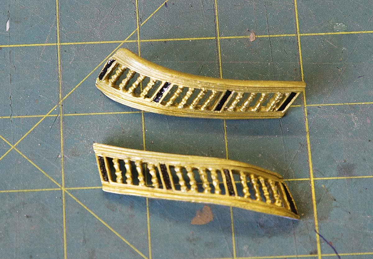
Hi Pete, You noticed, I'm a bit out of sync with my pictures and description. I think this photo will explain. I've given the castings their final shaping and painted them ready for fitting. The black on the oval castings was so the the gold on the relief would stand out. Ken
-
Hi Steve, Coming along nicely. I like the way you're putting good informative step by step pictures in your log, these give an excellent insight into your work. Ken
- 291 replies
-
- 4
-
-
- bounty
- billing boats
- (and 1 more)
-
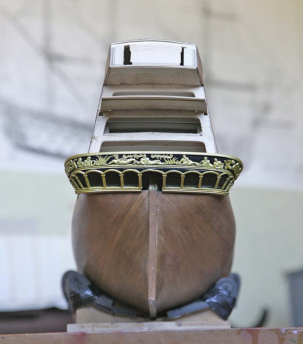
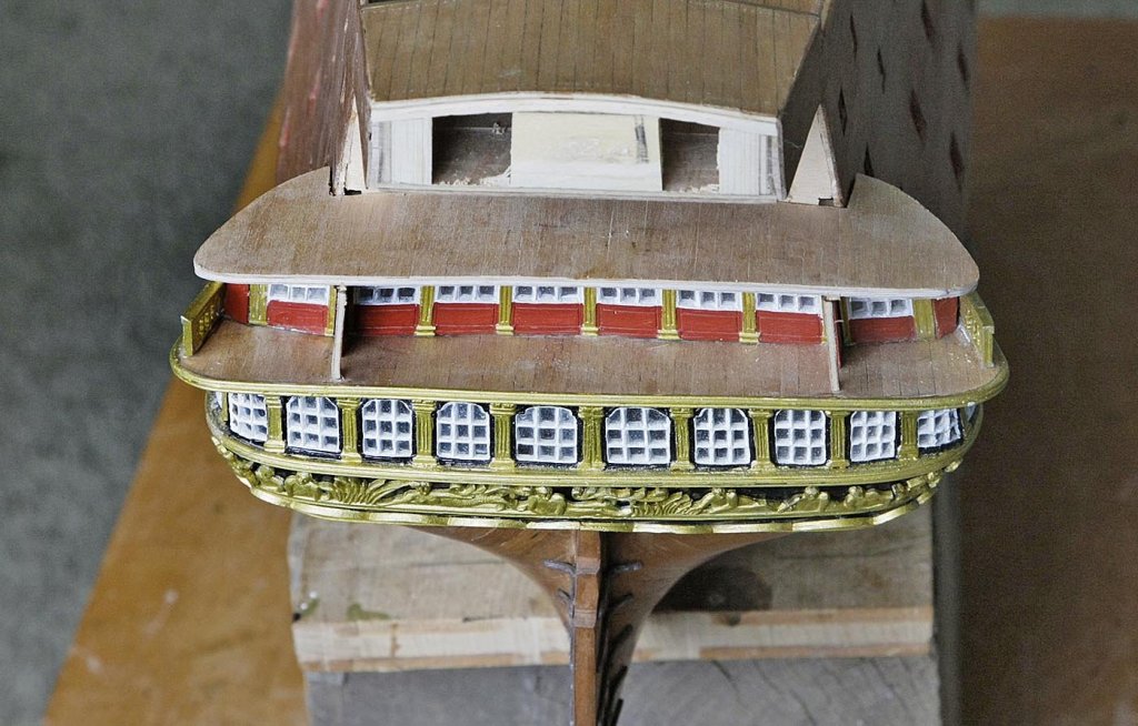
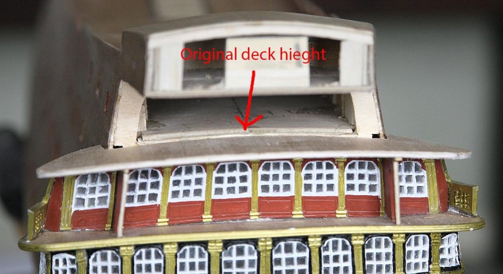
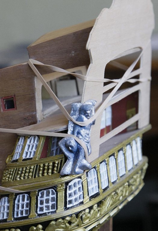
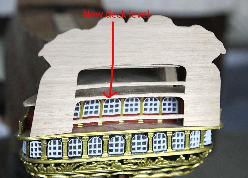
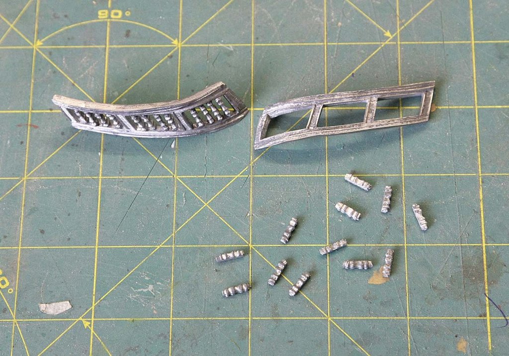
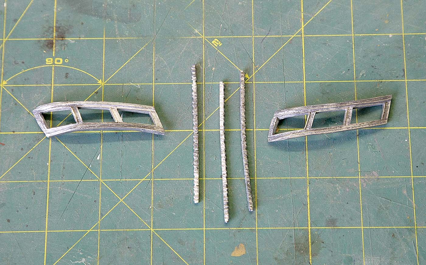
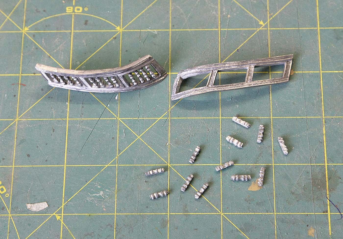
Hello Everyone. Again thanks for your likes. Here's the latest. I have now made, planked and fitted the next transom deck. As I said I cut away the original deck so that I could fit a one piece version that would be much easier. This deck when fitted was about 3mm lower than the original at the front, but because of the upward slant of the galleries it fits perfectly in line at its rear with the transom facia's deck position. I now realise that The original deck would have been wrong as its incline was shallower than the gallery decks and would not have fitted at both the forward or rear part at the same time. At Pete's suggestion I checked that the cast figures at the rear edge of the transom would fit as it would be easier to make any corrections at this stage. I hadn't given any thought to this but as luck would have it all is ok. I have shown the pieces that make up the next level of the gallery. They are now glazed and shaped ready for painting. Ken 9001.doc
-
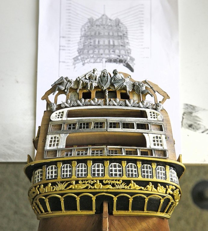
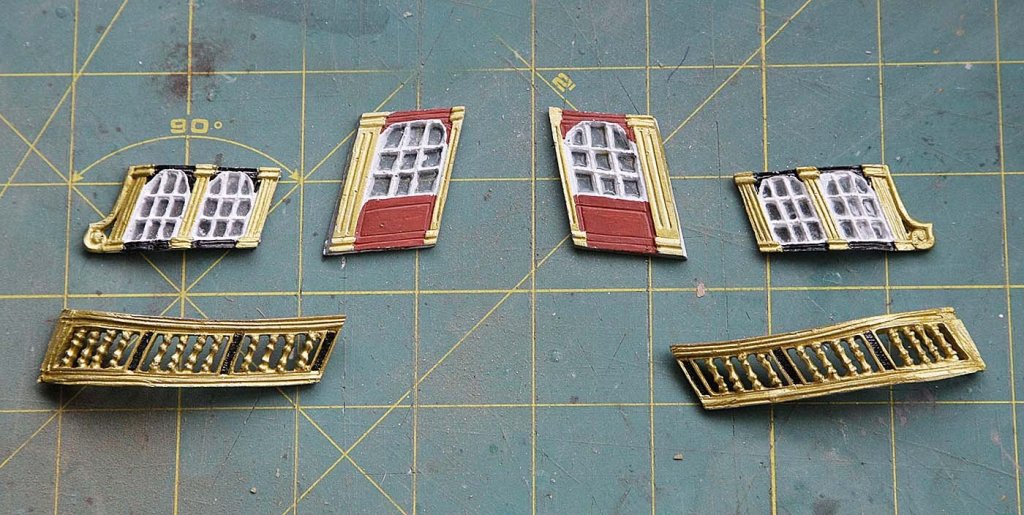
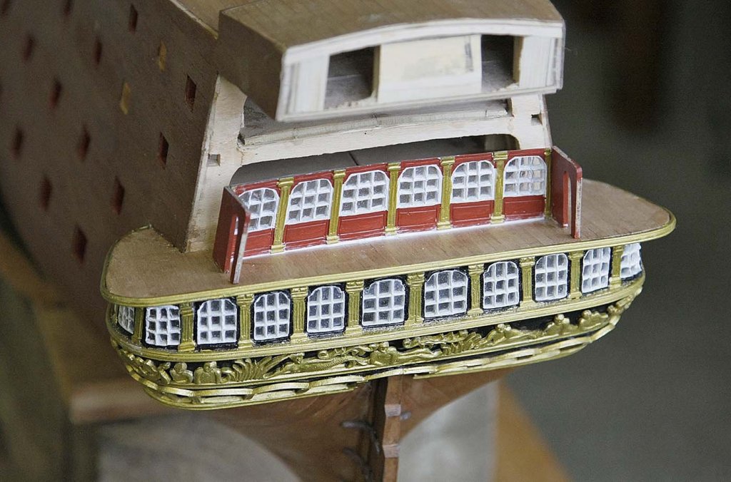
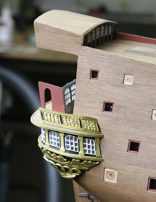
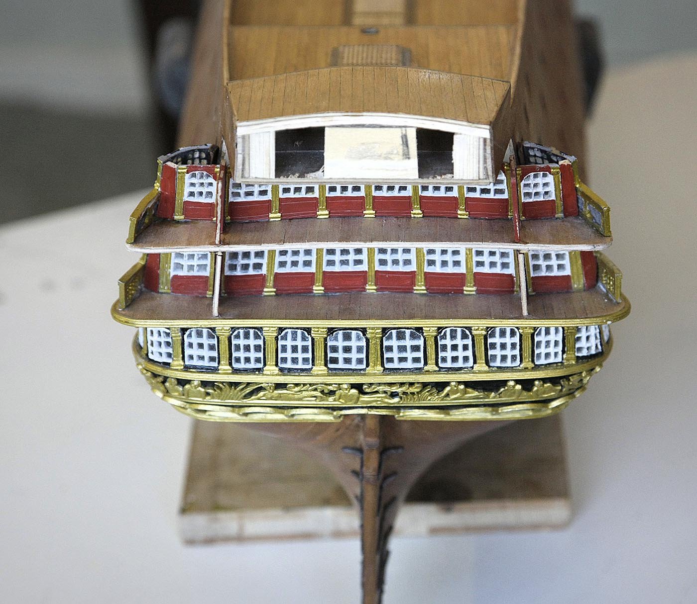
Hello Everyone, Here is the latest update. I've shown a photo of the next pieces of castings that need to be assembled and fitted into place, they were painted,shaped and ready to go. Mark did point out that this was a difficult part of the build and was tricky to get right, I now know what he meant. I had already built up the middle inner section of windows and the side doors, these were in their exact position, the next step was the windows that linked up with the outer cabin windows and the hand rail-balustrade. Each of these needed setting at an angle so that they would not only be in the correct position but that their edges perfectly aligned with each other at the same time. I found that no matter what I did even after bending to shape I could only get them either to align or set them looking ok in the correct position but not both together. I decided rather than follow the accepted way I would make it easier for myself and fit the outer windows and balustrade in as correct position that I could according to the plan without regard to it aligning with the inner window, this after all is what will mostly be visible. I then fitted the inner cabin window, again without regard to it making contact with the outer windows, but in a position that looked ok, this left a gap of between 2mm-4mm. I made up a piece and glued it into the gap, when painted it looked as if it should be there. I'm pleased with the result and glad that I didn't let myself get frustrated trying to get it absolutely correct. Next I will be making the deck to fit above these cabins. Ken


-
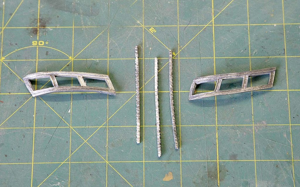
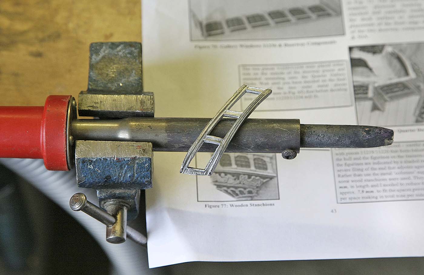
Hi Pete, Thanks for that. I was quite surprised with those stantions they were not what they first appeared to be. Initially I thought that they were just random serrations along their length but on closer inspection I saw that they had a front and rear and the pattern along the length was a regular repeat. The pieces also had notches at regular intervals which made it easy to break them off at the correct size leaving about .5mm each end to file the correct angle, when fitted the stanchion patterns lined up uniformly. I thought that what at first looked simple was really quite well thought out by Euromodel. Ken
-
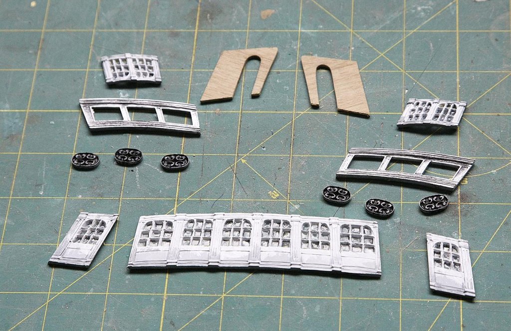
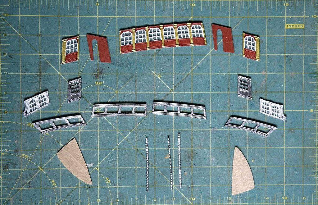
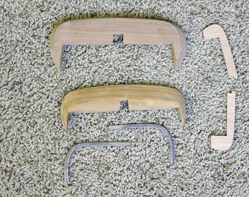
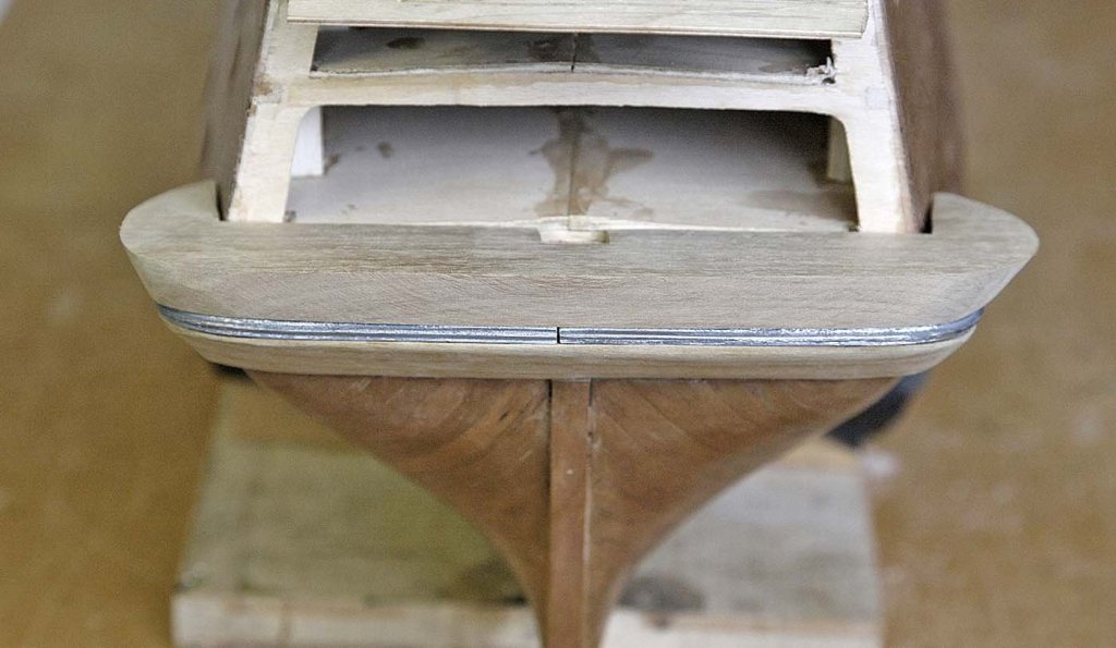
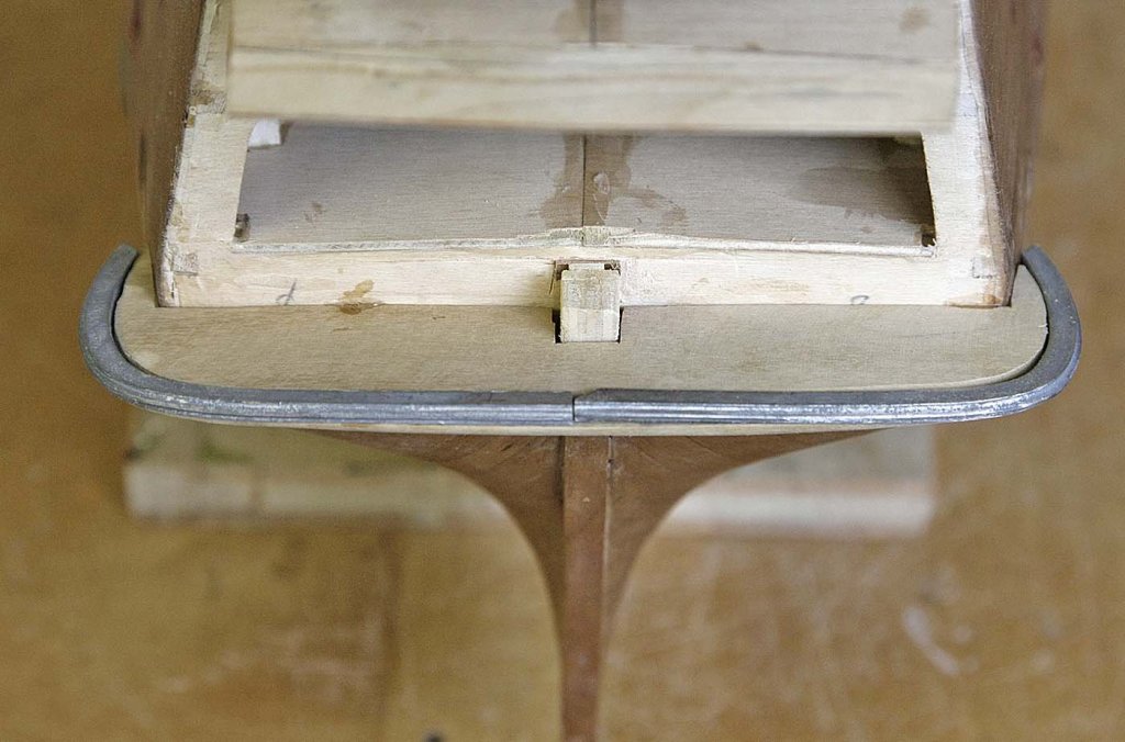
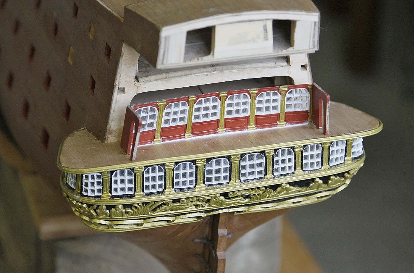
Hello Everyone, Thanks for all the thumbs up on my build so far. Anton, thanks for your comments, at least I'm not having to make all my own decorative castings like you. I'm following your build and really enjoying the effort that your putting in, great work. Mark, thanks for your encouragement, I appreciate your comments. As I said, I found the first part of the gallery quite a challenge. I knew what I wanted to do but it was my first foray into working with cast parts and I was getting into difficulties trying to bend it in different planes, I would get one area right and it would then cause another area to not fit, a frustrating day but a learning curve. I approached the next level which is more difficult with a different mindset, with the experience I'd gained I was more confident, more relaxed about it, no trying for quick results. I was also annoyed with myself for not photographing my efforts, so at least for the rest of the transom I will try and photograph everything that I do bit by bit, warts and all. I hope that there won't be too many boring pictures. First I shaped the stern so that the facia would sit at the correct angle and have the right contact with the decks, Photo. I then had second thoughts, The way that I made and fitted the deck above the lower part worked very well so I decided to do the same for this deck. I cut off the original deck flush with the rear bulkhead. I'll cut my deck out in one piece and use the supplied deck side pieces as a guide for the edge curve. Photo I painted and glazed the inner windows and side doors, I only glazed the others, I'll paint them after shaping, ( lesson learned ). I've shown a photo of the parts needed for this section of gallery After careful adjusting I set in place the inner windows and side doors, Again I used canopy glue with small dots of cyno to hold it together whilst drying. Photo. Next I cleaned up and bent to shape the side railings. The solution that I came up with for bending the cast parts was to use the shaft of a large soldering iron clamped in a vice, this gave enough heat without melting to easily bend these castings, ( another lesson learnt ). Photo Next was to make up the balustrades. Euromodel supplied a cast serrated strip which on first appearance looked a bit naff and I was disappointed, Photo. However not having anything else at hand to substitute it I continued, I cut the pieces to size, this was very fiddly, as they were to be glued in with cyno they needed to be filed to an exact fit. Once I started to fit them I changed my mind about how good they were and I was glad that I hadn't substituted them, at this scale I don't think that they could be improved on without a great effort or cost. Photo I painted the rails and the picture shows them just resting in place. A good session. Ken


- 424 replies
-
- 11
-
-
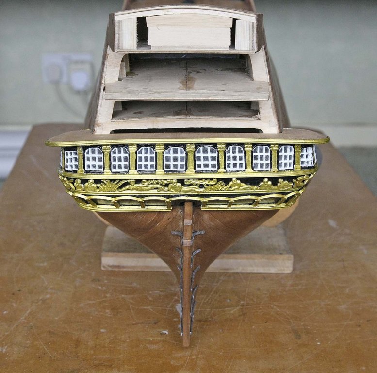
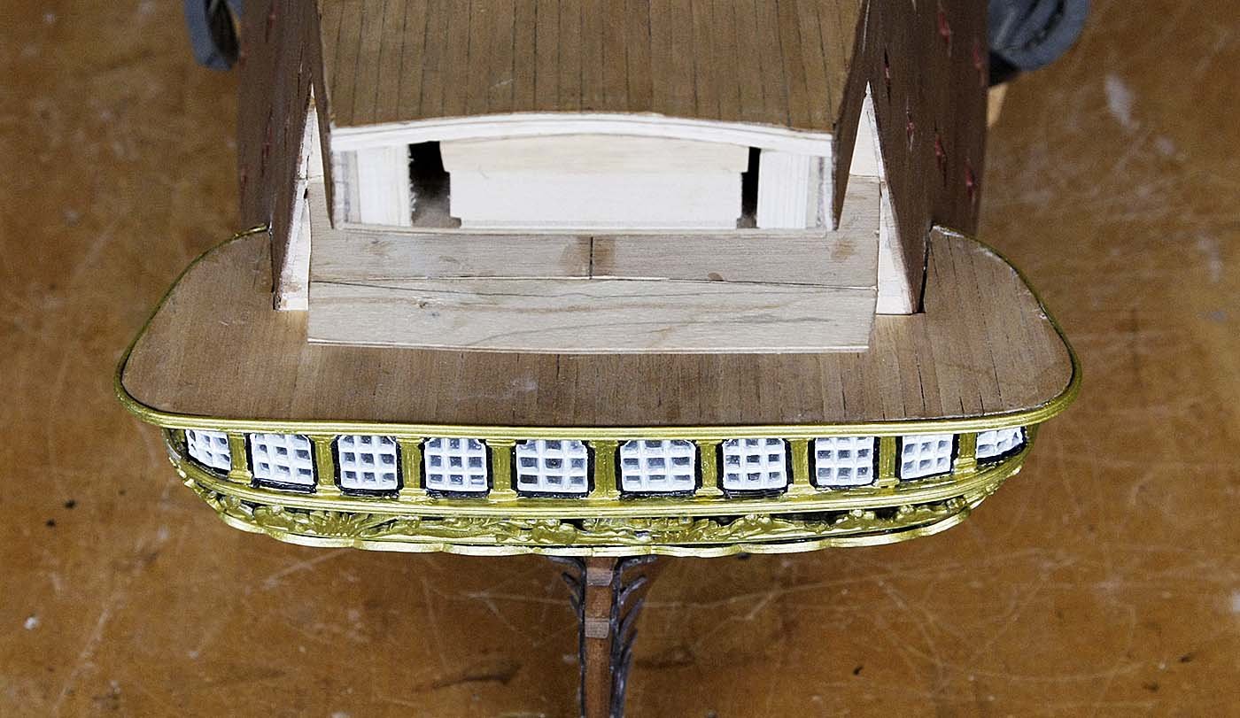
Hello Everyone, Here's todays update. I have just finished the first set of windows of the transom. Those of you that have done this will know my feelings on this part of the build, I have sat down and opened a beer to try and relax again. It was like trying to pluck a chicken with boxing gloves on. The plans were of no help at all and yet again I resorted to others logs, especially Marks excellent, well documented interpretation. I had already painted the windows thinking that it would be easier to just touch them up after fitting than trying to paint them in place. I spent quite some time coaxing them into a shape that they would sit on the transom support and have some sort of relation to each other, had I not seen examples of it having been done I would have said that it was impossible and given up but perseverance and I think a bit of luck got me there. I used my canopy glue to attach them with some small dots of cyno to hold them in place whilst it set. I used this stuff because of its gap filling qualities, it is water soluble so any excess can be wiped away unlike epoxy which is pretty messy. For making the deck above Euromodel supplied some precut pieces, I found that these appeared to be the wrong shape and couldn't be made to fit so I used Marks idea and made up the deck from one piece of ply instead of the three supplied, I planked it and glued it into place, I also had some spare decorative strip which I glued around it's edge. I then touched up the whole area. I would normally have photographed each step but on this occasion I got so involved I didn't pause to do so, probably a good thing as I might have thrown my camera out of the window in frustration. I am now more impressed with other builders efforts in this area knowing the difficulties. Having said all that I am not disappointed with the result, in fact I am rather pleased with how it looks so yet again perhaps Euromodel got it right. Ken

- 424 replies
-
- 12
-
-
Hi Pete, In answer to how I did the glazing, first I used a Zap, Pacer product, Formula 560. It's a clear canopy glue that's used for fixing glass cockpit canopies to model aircraft. A thin film is very strong and is crystal clear, it's also cheaper than the stuff from Micro, for less you get twice the amount. It can also be used as a gap filler and will take paint. I first paint the white area of the window frames so that I get the depth then at the rear I smear the glue thinly over the surface until you get a film over the gap, just as you would when you were younger making bubbles from your mums washing liquid. Just leave to dry, even a thick layer becomes very clear. Ken
.thumb.JPG.11f8630d752a1e40c9f9289c4b9e1d0d.JPG)
-
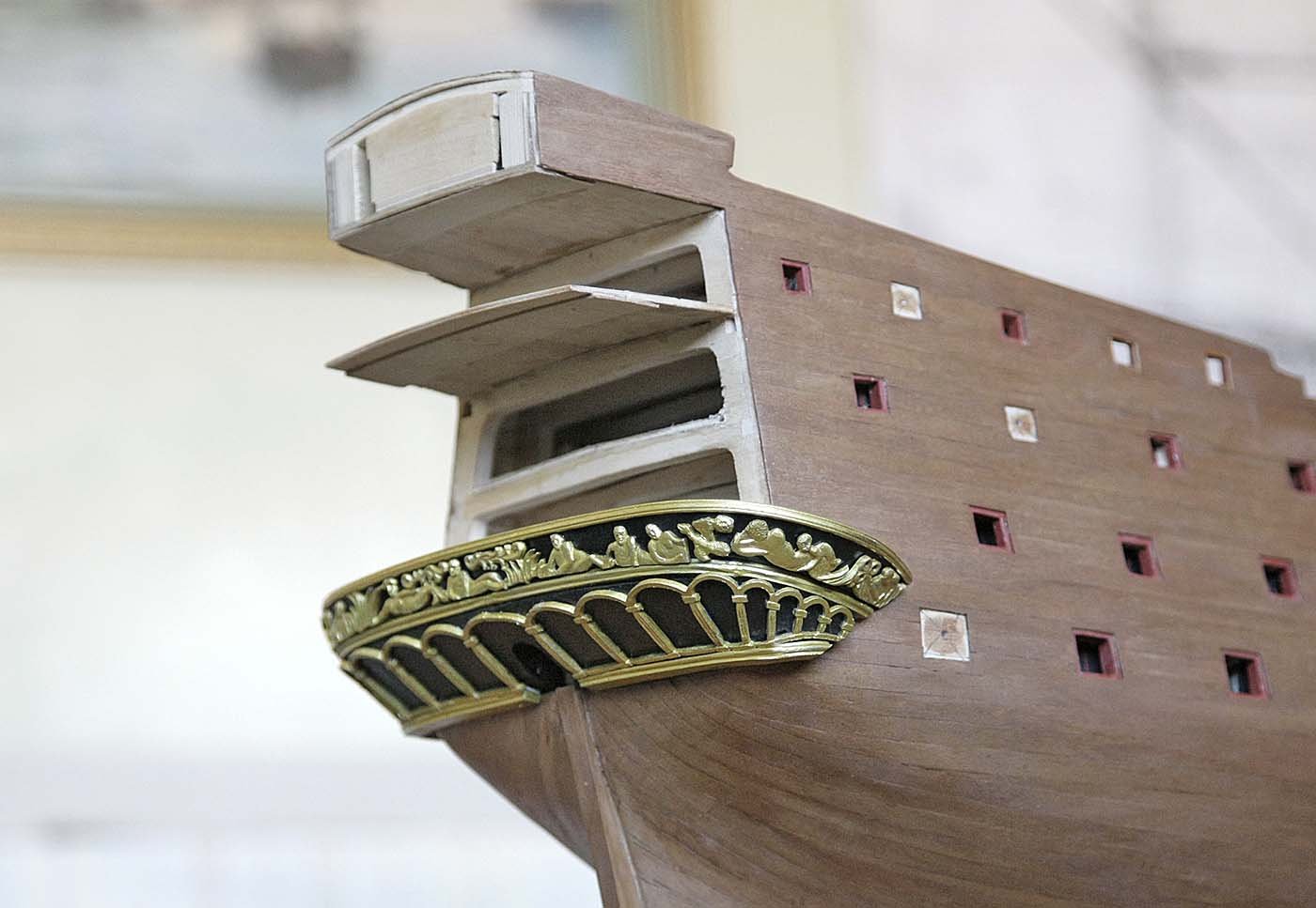
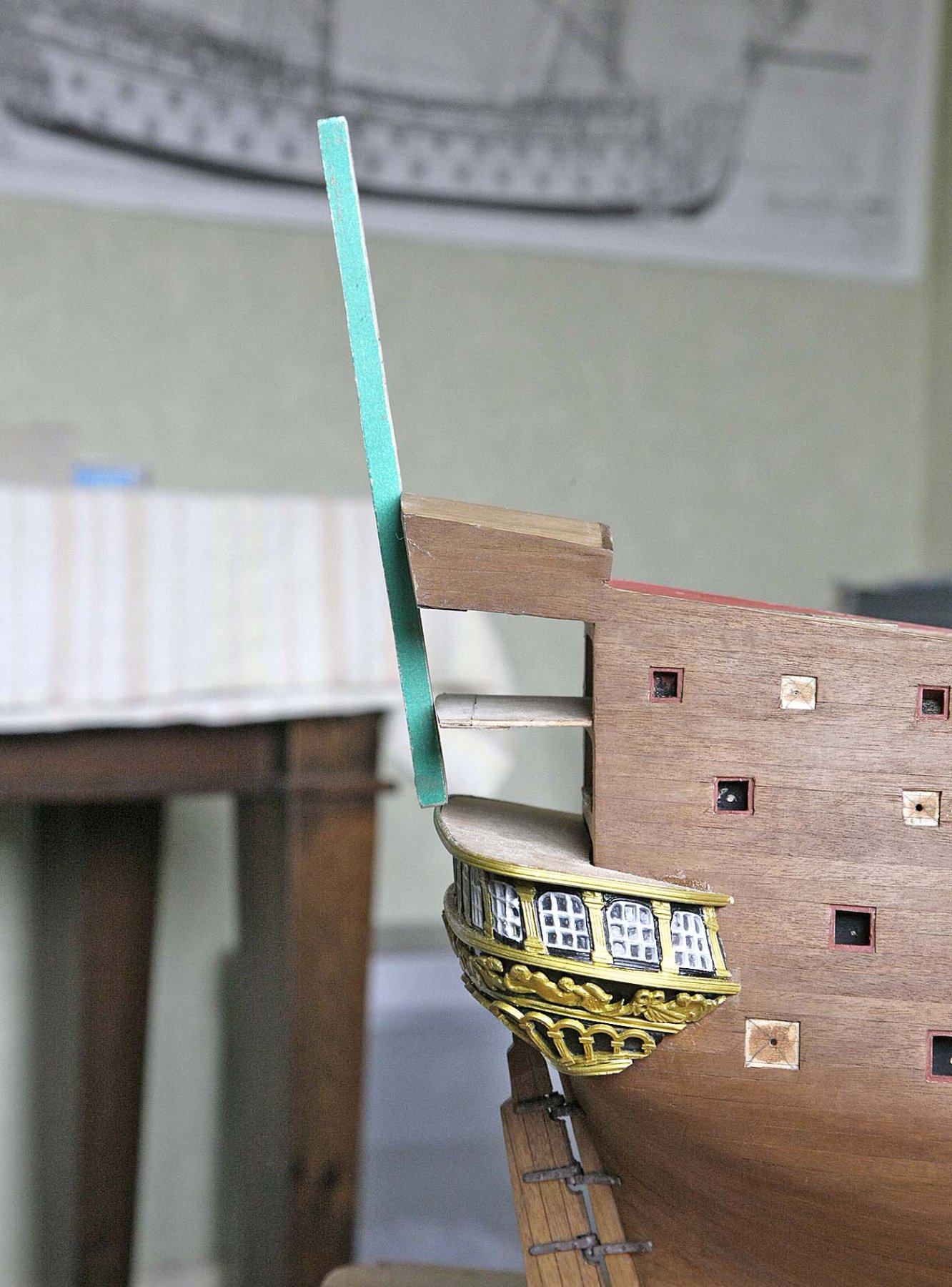
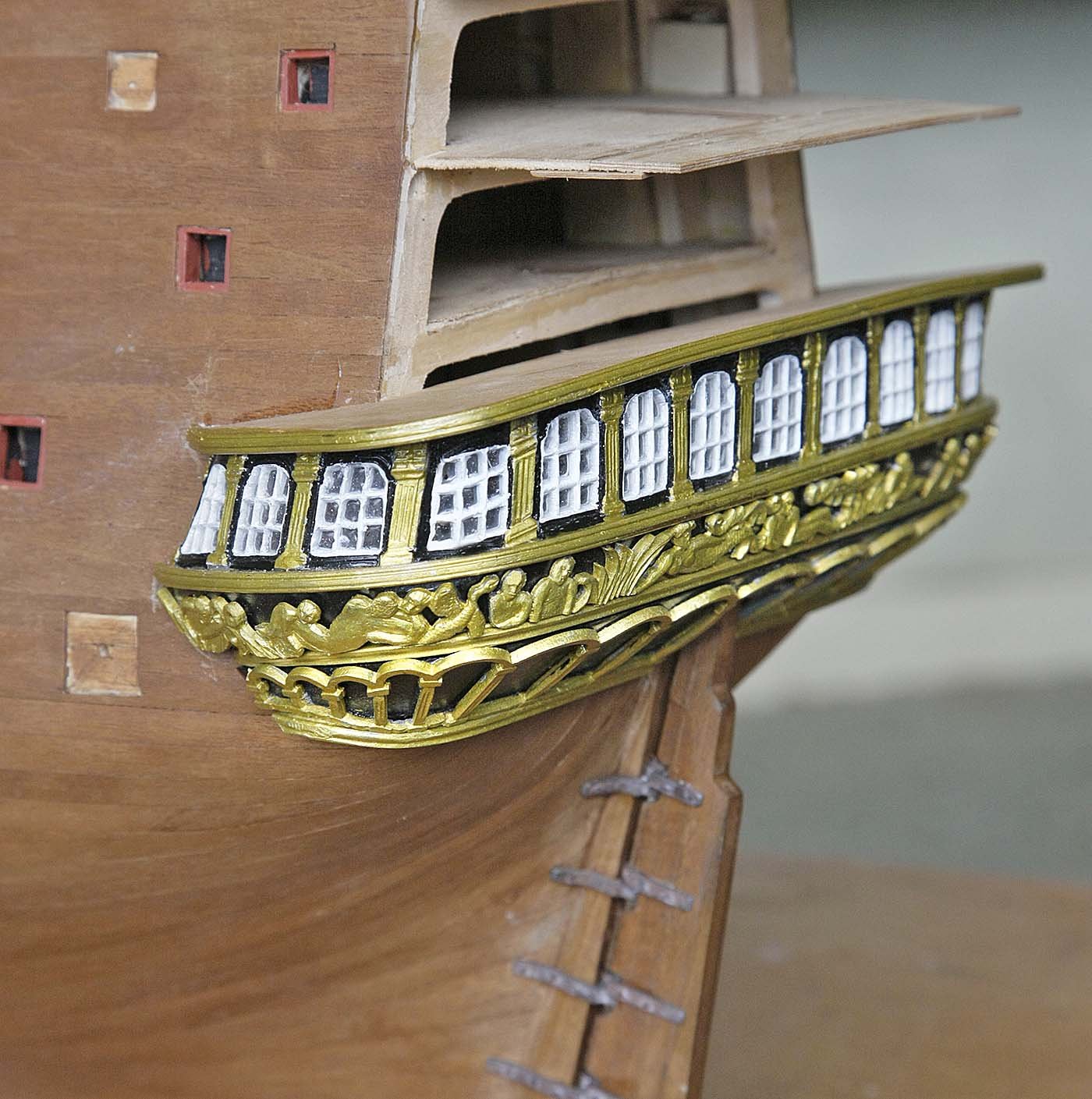
Hello Everyone. Another update. I've now done the rudder and attached it. Pete has revised and updated his notes recently showing much more detail having drawn from the experience of other builds. One area that more info is given is that of the rudder. I used the supplied hinges and aged them a little with a brass blackener. The shoulders of these hinges are quite thick and would have needed fairly deep cut outs in the rudder or big battens to avoid a large gap with the sternpost so I compromised and used both the cut outs and battens to achieve a reasonable if not authentic look. The moulded bolts on the hinges were too pronounced so I filed these back a little, I trimmed and bent them to shape, secured the pins and attached them to the hull using cyno. I normally nail them on but as the bolts were already embossed on and looked quite good I decided to glue them, if they hadn't felt secure I could have nailed them but believe me they are solid. I had doubts at first but I'm pleased with the result. I have also started on the gallery windows. Using a scalpel I gave the glazed area a final trim, primed glazed then painted them. I am going to keep to a simple colour scheme of black, white and gold, I think that these colours compliment each other and give a good clean contrast. On my previous post I said that the gallery supports were only ok but would do, I think I was a bit harsh on myself because leaving them overnight and returning in the morning I now think that they are quite good and again I'm pleased with the result. I think that I was expecting to be able to shape the castings around complex curves and for it to stay flat against the surface like photo etch but it's a different beast, it's quality lies in its depth and rich detail but should not be viewed from too close up to see it at it's best. Just putting my opinion down here. Ken

-
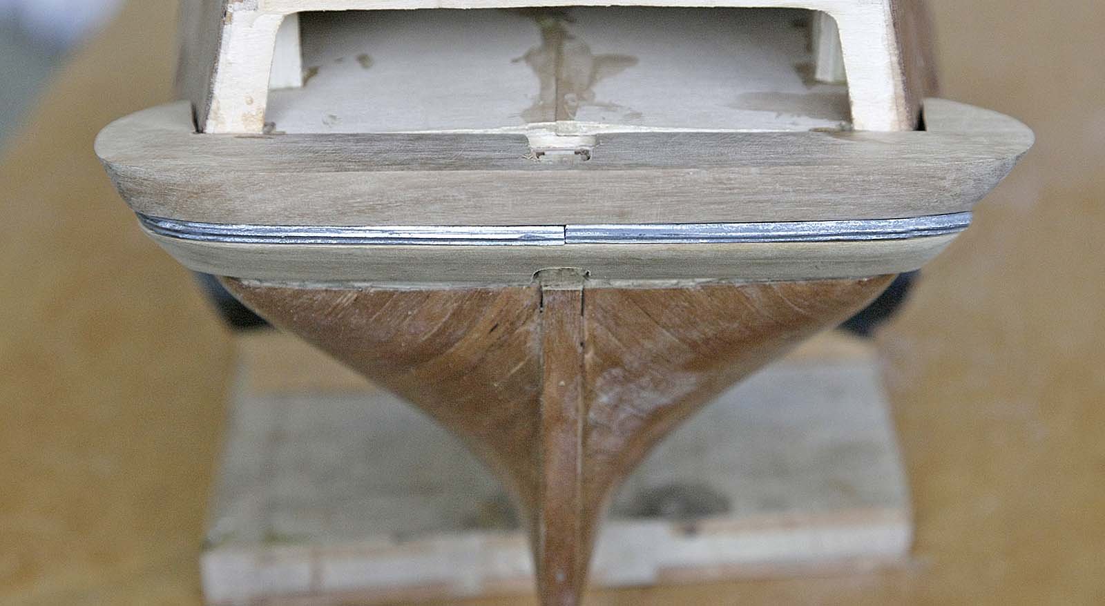
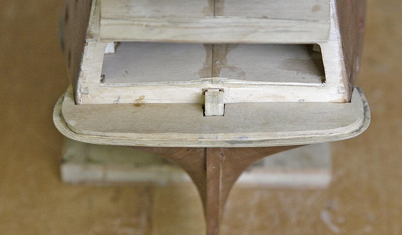
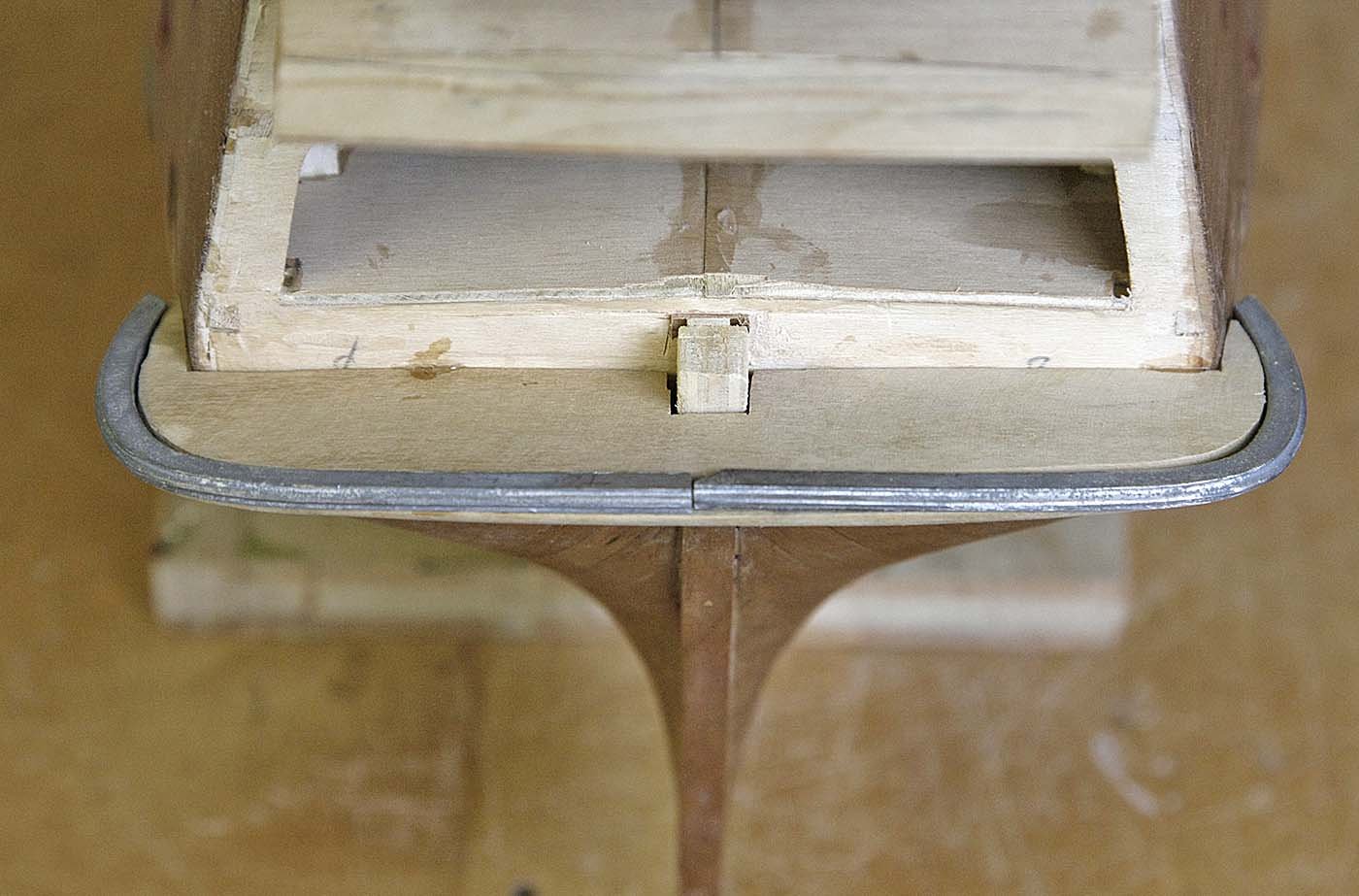
Hello Everyone, A small update. I have just finished the lower transom support and glued it in place. I found it to be quite an awkward piece to make, nothing seemed to end up being a perfect fit, it turned out only ok but it will have to do. Next I'll be tackling the rudder, Ken


- 424 replies
-
- 11
-
-
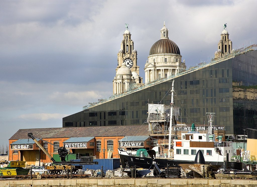
Hi, It's good to see that this site is truly international, I'm surprised that I've got followers from all corners of the word and all showing interest in aspects of my log. Dilbert, Yes that picture was taken at the Albert Dock, I hope your friend enjoys the pictures of his home area, I'll keep posting a fair selection from here so keep looking. I'm sorry that we've exported a Liverpudlian to you, they seem to get everywhere, just keep an eye on your wallet! This picture is again of the Albert dock taken just to the left of my last picture of the dock, you can see the recognisable Liver buildings in the background. Ken
-
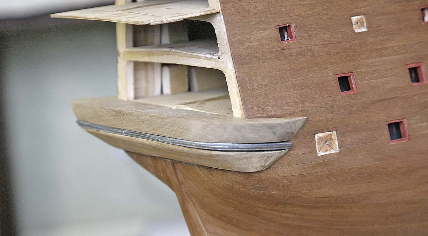
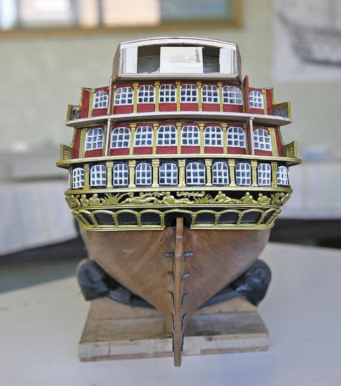
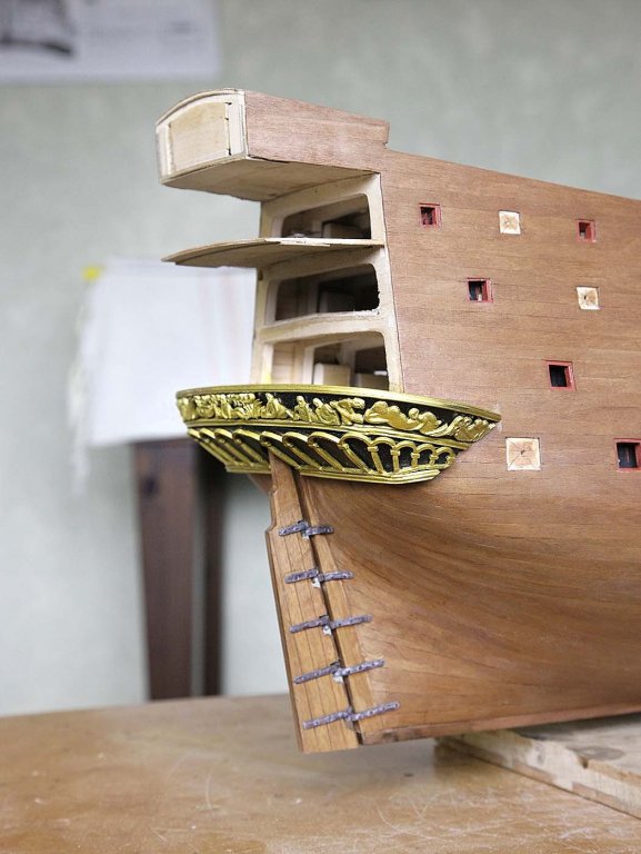
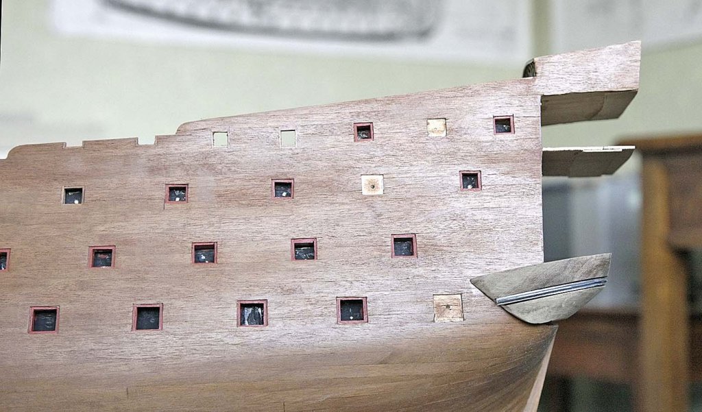
Hi Mustafa, Thanks, welcome aboard my log. I said that I only had minor tweaks to finish this part off, well they took me the rest of the day, no quick fixes I'm afraid. I've now glued the two pieces together but just slotted the casting in place so now I have a good idea of how it will look. I've shown a picture of how it sits at what will be its final position. A little filler will be needed but as it will be painted I'm ok with that. ken
-
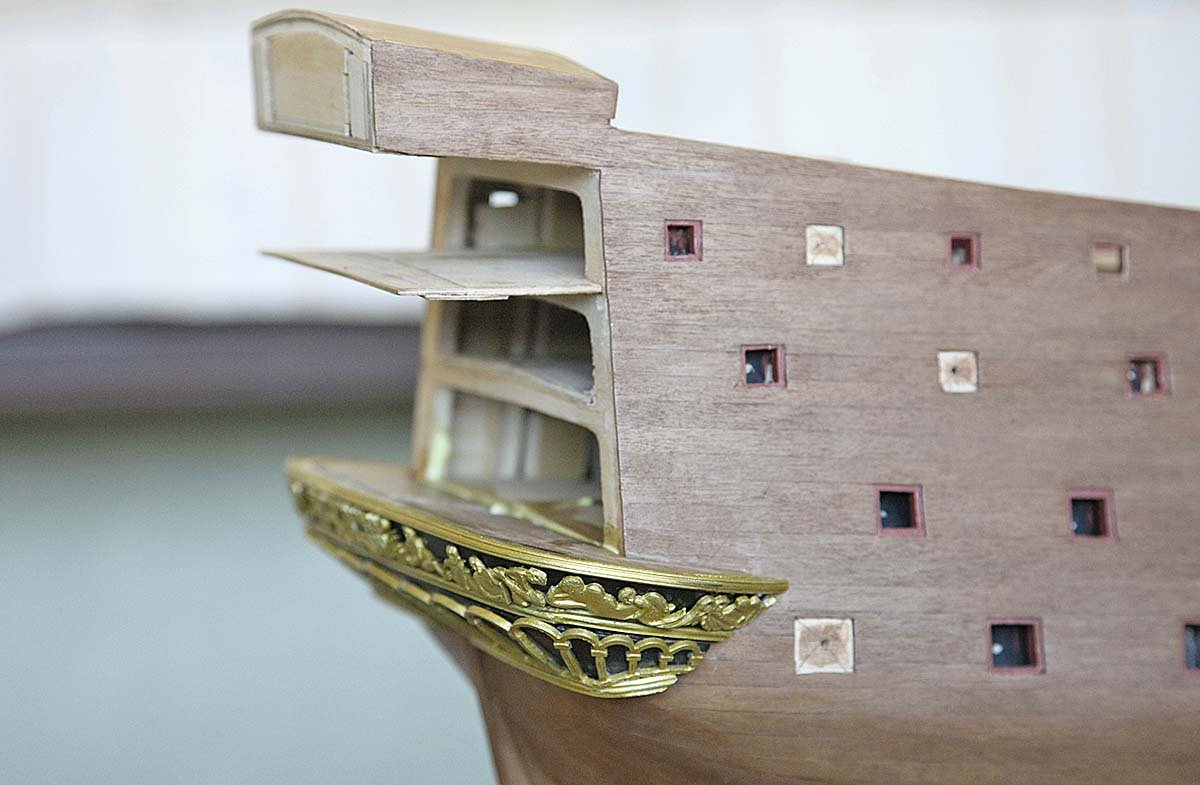
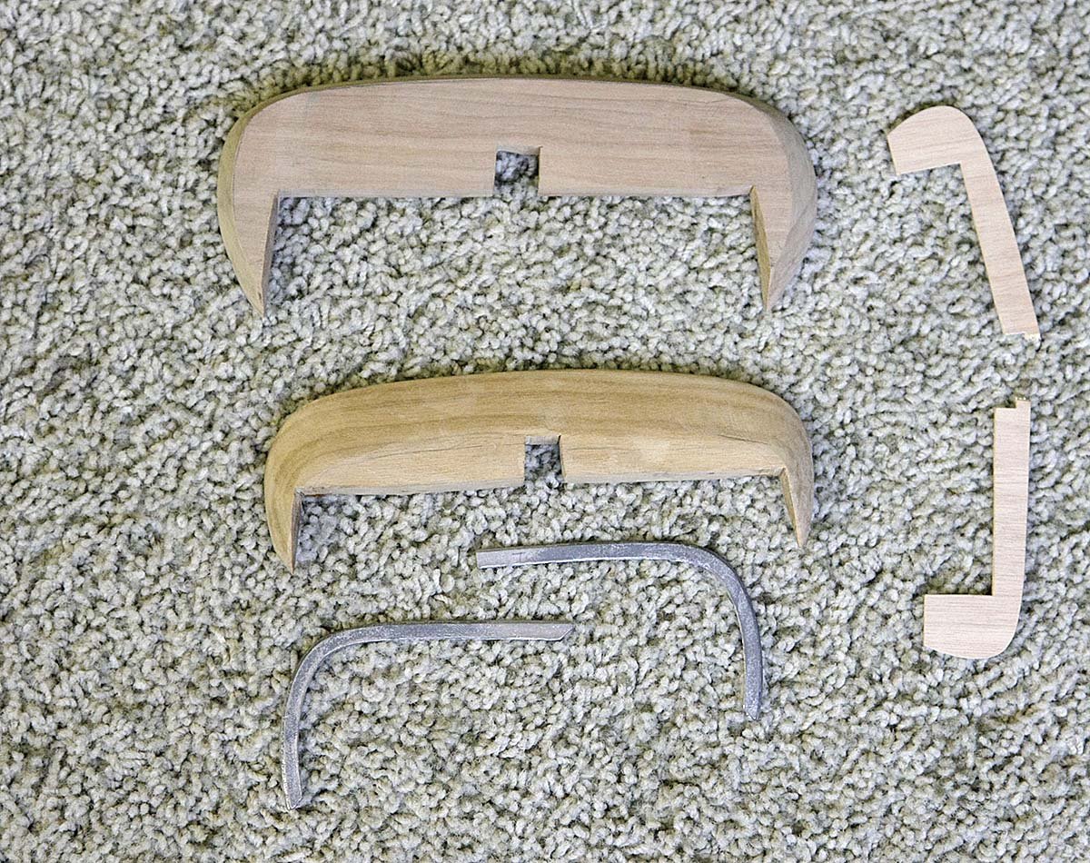
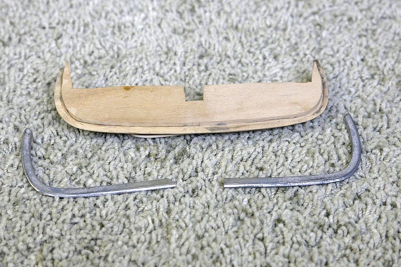
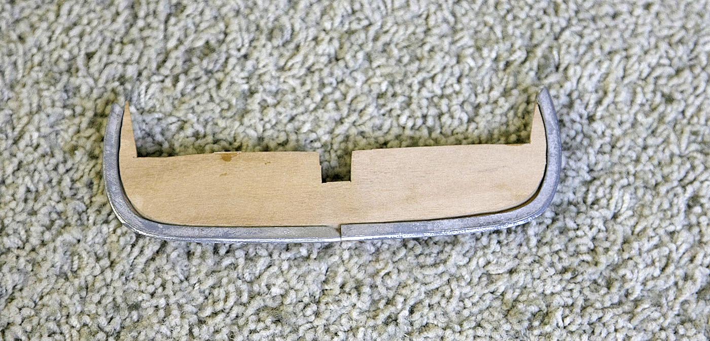
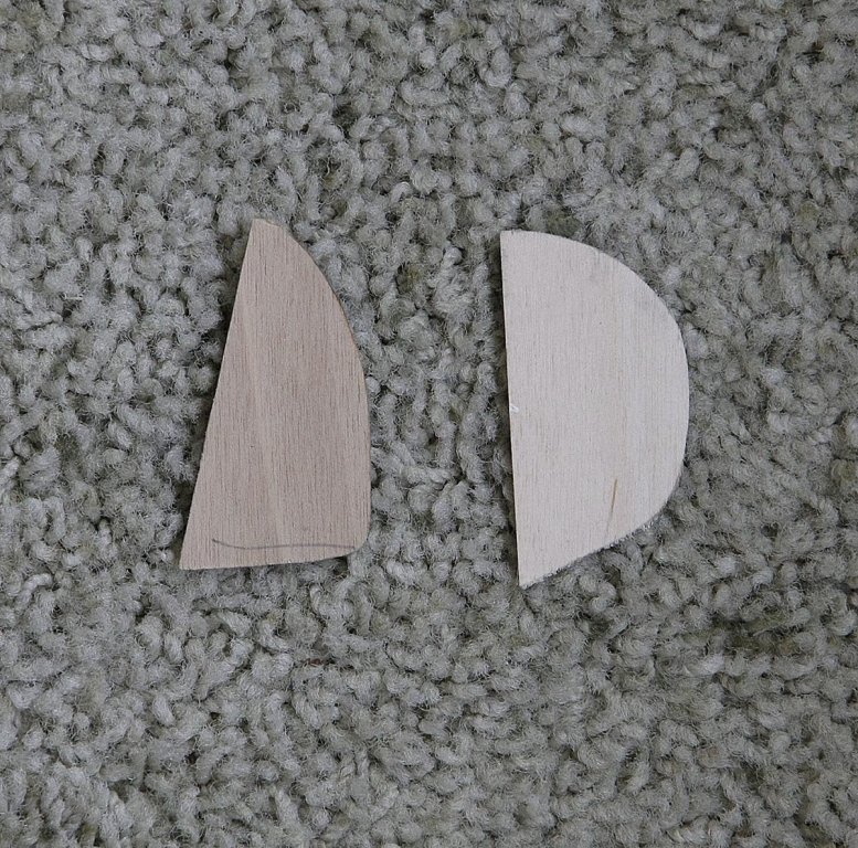
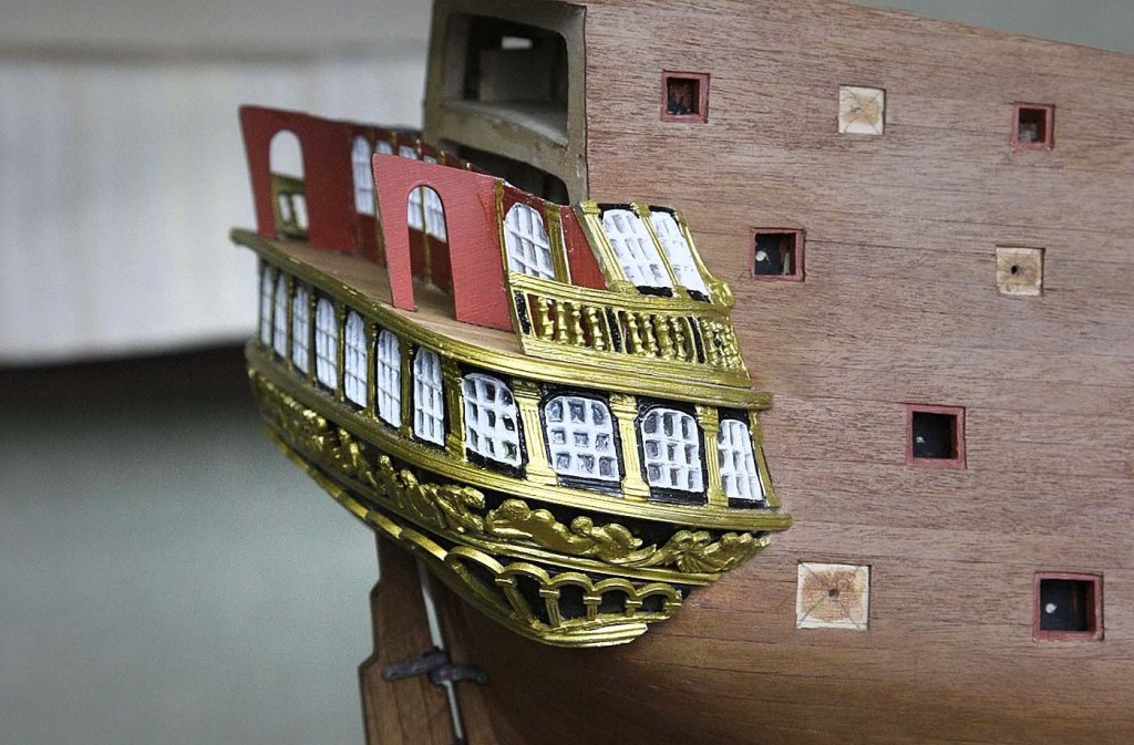
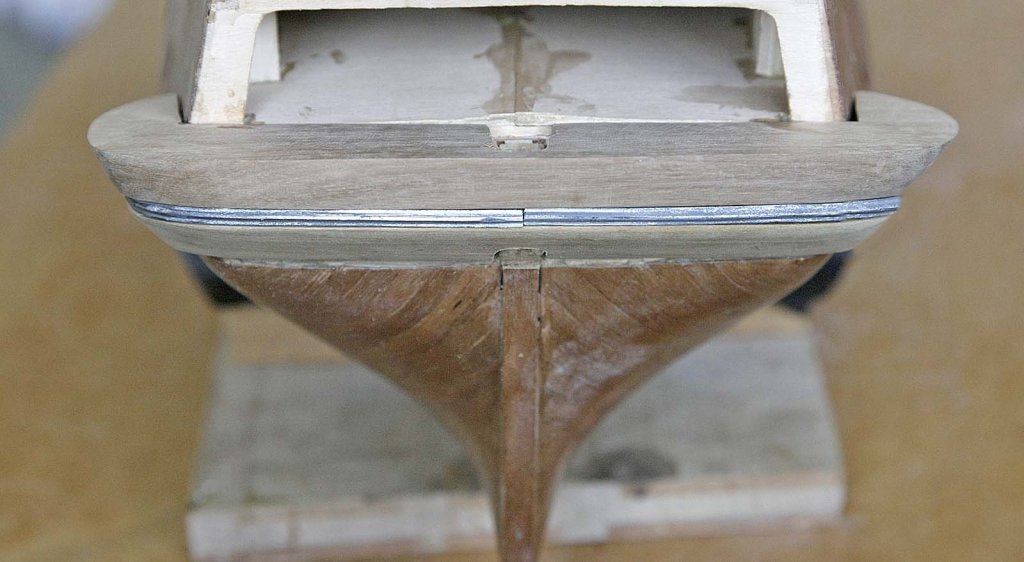
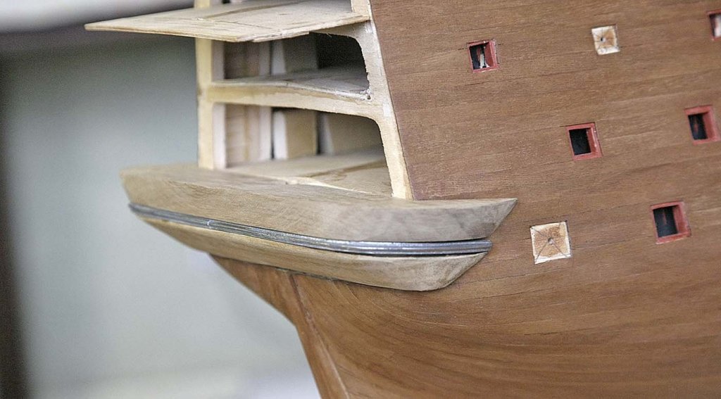
Hello Everyone, Thanks again for your likes and complementary comments. A long day and a bit has seen the lower gallery supports made with only the rudder hole and a slight tweak and final sand to do. I was moving into new territory here and didn't know how it would turn out but again I'm delighted at the result, more grins here. First I'll say in fairness to Euromodel I found the piece that in my last post said was missing, it was in the bottom of the box, it had broken in half and I hadn't been looking for something that size, the annoying thing is that having made a new piece it wasn't needed at all, ah well. I took note of all the advice that I'd been given about carving small amounts at a time and keep checking against the hull. I would normally guess what size would be needed and hack away only refining it near the finish and if it didn't work start again, this would not have got me anywhere with these supports, I was surprised just how critical accuracy was so the new me just kept chipping, carving and sanding bit at a time all day. You'll see in my pictures what was done, the only thing I would have done with hindsight would be to carve the recess for the casting before I had done the curve because after it couldn't be held in a vice because of that concave curve and was very awkward to hold. The outer edge of the supports profile was quite accurate and needed only minimal shaping. I have taken some of the decorative castings for this area out of the bags to see how they would fit and Wow, they are something else, better than could be imagined without seeing them in the flesh. I hope that I can do them justice. Pete has shown the gallery cast parts, their numbers and position that they go, on checking I realised that by opening up the windows which form the bulk of the gallery I have filed away the numbers, er! Finishing off I will say that I don't envy those who started this kit without all the logs and information that is now out there, I don't know how they did it, the plans for this difficult area are vague to say the least. It wasn't overly difficult but it was knowing what to do, I couldn't have figured it out from the plans alone. I'm sure there will be other areas like this and I think that this is why it gets a reputation for being such a difficult model to build. Just my thoughts. Ken Not glued yet, when held the gaps aren't there


-
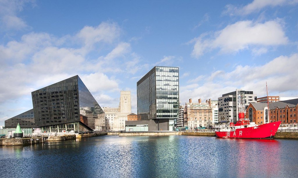
Hi, No progress ready to show for today so here's another picture of Liverpool. In the 90s Liverpool like many other cities went through a period of regeneration, fortunately the planers got it right. They left a large area of the old city docks from the 19th century untouched apart from a good renovation and turned the area into a heritage site. Now the Albert Dock is a lively recreational area with museums, cafes, entertainment venues and artisan shops all within the old wharfs and warehouses. There are several dock basins, the old customs sheds, pump houses oh and some pubs. It attracts a variety of old sailing ships from around the world and you could easily spend a day there and it's all free. The first picture that I'll show of the area is number one basin which looks out onto the new city, the red boat is the old Mersey light ship which is permanently moored there. Ken
-
Hi John, Thanks very much for your likes and comments. It takes time and some effort to do these posts but knowing that they're being read and are appreciated makes it worthwhile to me. So welcome aboard my log. Regards, Ken


.JPG.1e95a5325aa1580ea23e8b609a7647fb.JPG)