HOLIDAY DONATION DRIVE - SUPPORT MSW - DO YOUR PART TO KEEP THIS GREAT FORUM GOING! (Only 13 donations so far - C'mon guys!)
×

Kenchington
-
Posts
663 -
Joined
-
Last visited
Content Type
Profiles
Forums
Gallery
Events
Everything posted by Kenchington
-
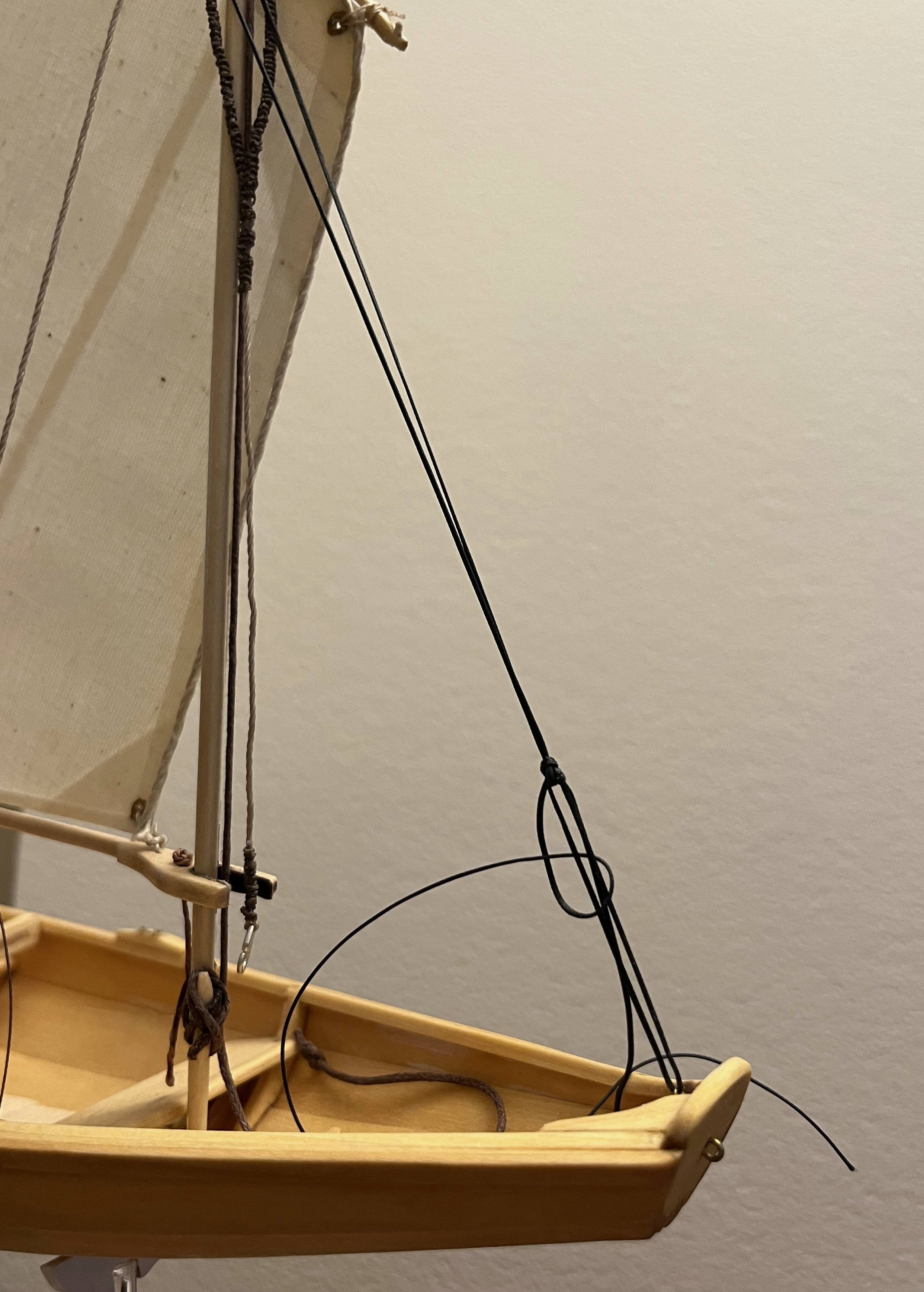
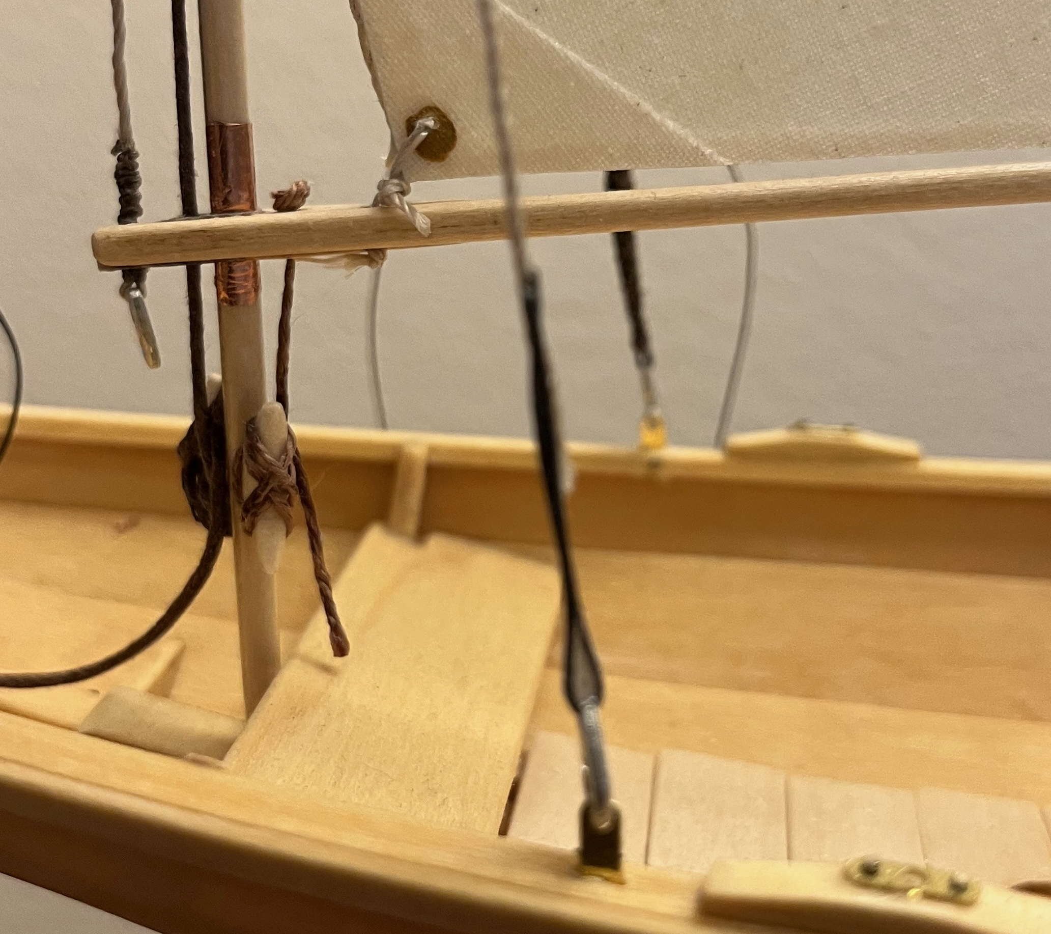
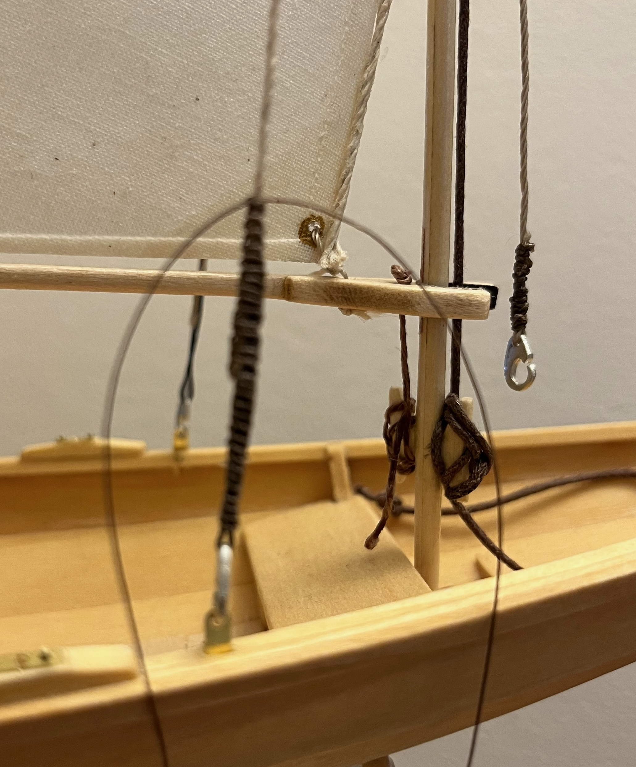
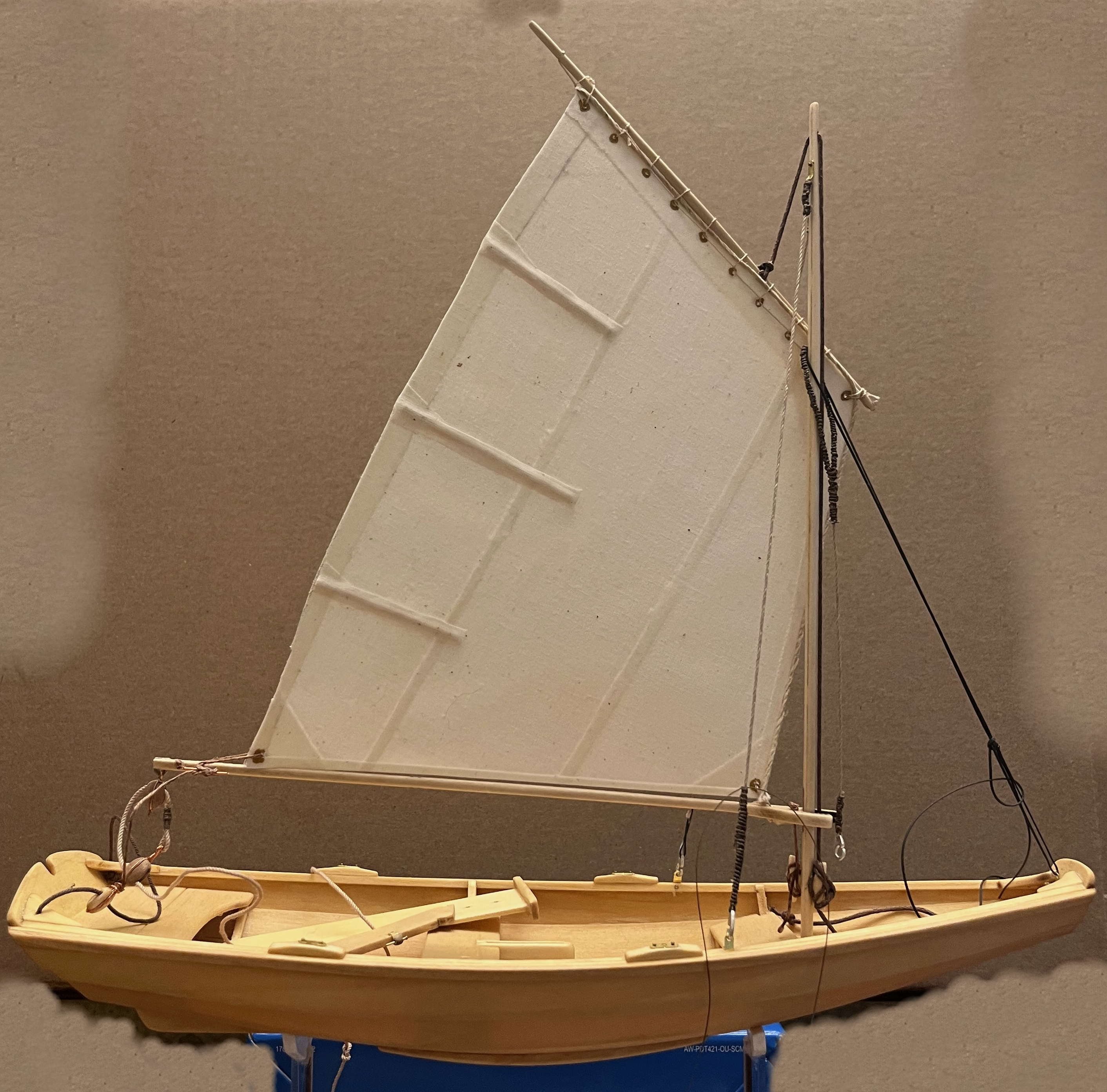
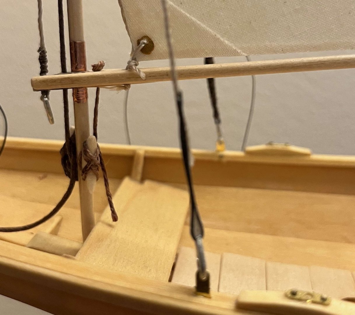
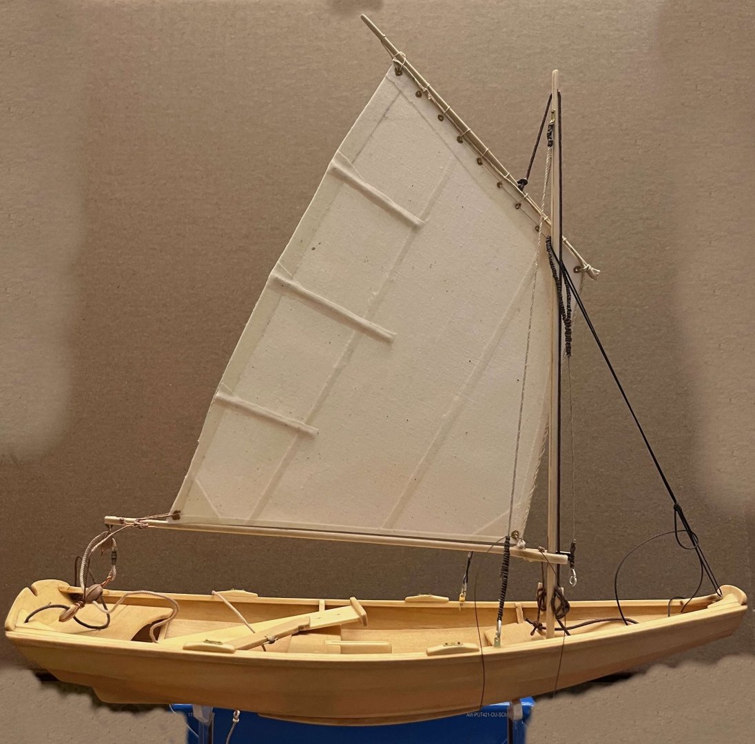
 Six months gone since I last made any progress on my pram. Like others, I have been caught up in a whole mess of tasks (some rewarding, others less so) that have drawn me away from ship models -- from model building, though they have not stopped me being an annoying know-it-all on MSW! Back in April, I had come to accept the forward rake of my pram's mast and finally stuck when my attempts to produce the sort of tiller that I think the boat deserves proved more demanding than I had expected. However, staring at the model all through the summer, I decided that the rake had to be adjusted and that that would be an easier route back to re-starting work on the pram. So ... I still think it is best to get both shrouds the same length, hence the mast upright when seen from ahead or astern, then worry over tension in the rigging while finalizing the forestay. But it is clear that the rake has to be set approximately before starting on the shrouds. So I began by unhooking the existing forestay and rigged a length of thread in its place, adjusting that until I got the rake I wanted: Next, I cut away one shroud where it passed around its hook, at the chainplate in the rail. I cut away the "serving" (which I had faked with a length of Westcountry whipping) and "spliced" on a length of thread by gluing it to the cut end of the shroud with CA. Passed the thread through the eye in the hook, pulled until the mast was upright (port to starboard) and glued the other end of the thread back to the shroud: (Phone camera decided to focus that one on the mast, not the nearer shroud, but you can see the repair.) Next up, repeated that with the second shroud -- judging the mast upright by eye, though it proved to be as close as made no difference when I later checked with a small square laid across the rails. I have hidden the mess of glued ("spliced") ends with a lengthened "serving", though that's awaiting a touch of CA before I clip the ends of the serving thread: Again, the focus is off and the "serving" is lumpy where it passes over cut ends. Still, I now have the mast in a far preferable position: Still have to "serve" the port shroud, then make a similar adjustment to the length of the forestay. The mainsheet and the rope sheet horse will need adjustment ti suit the lower position of the boom end, but that shouldn't pose problems. Then it will be back to making an acceptable tiller, followed by onward progress to model completion! Trevor
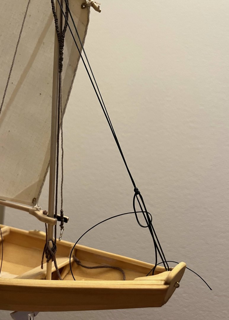

- 167 replies
-
- 7
-

-
- Norwegian Sailing Pram
- Model Shipways
- (and 1 more)
-
It will be primarily an issue of placing the centre of effort of the rig in relation to the centre of lateral resistance of the hull. Neither can be exactly determined from the paper plans and both move as the wind changes and/or the hull heels, so some "tuning" (mostly a matter of adjusting the rake of the mast) will be needed. You can start by finding the geometric centre of the (lateral) plane of the underwater body. Then sketch in possible sail shapes (by length of boom and gaff, height of the hounds, number of headsails etc.), find the geometric centre of each sail then that of their combination. Then adjust until the centre of the sailplane lies roughly over the centre of lateral resistance. I hope that's some help but it's about as far as I am competent to advise. You will need to know more, so look for textbooks on yacht design. Trevor
- 22 replies
-
- 1
-
-
- gaff sloop
- restoration
- (and 1 more)
-
[taboo] The Sloop Liberty Inquiry
Kenchington replied to Redondo113's topic in New member Introductions
Hi @Redondo113. Welcome to Model Ship World! I rather doubt that any definite answers to your questions exist. Even the boats of major warships, of the era that concerns you, are poorly documented. The boats of small merchantmen may be almost unknown -- unless you are willing to undertake a study of contemporary imagery for yourself. However, I will try a first stab at answers to your questions: A 48ft sloop would not carry either a longboat or a barge -- not as I understand those terms anyway. My best guess would be that she only carried one boat, as space would be very limited and there would not be any pressing need for more than one. As to size, I would guess "big enough but no bigger than necessary". Big enough would mean sufficient to carry two men at the oars and maybe a third steering, while operating in harbours where the sloop might anchor (including operating in a chop when the wind breezed up). I would doubt a need for anything more. Based on the capabilities of the lapstrake dinghies of my childhood, I'd guess that a 10ft boat would be too small, 12ft about right and 15ft unnecessarily large. Beam would be about 6 or maybe 7 feet, dictated by the geometry of the oars more than capacity or seaworthiness. On deck, on the centreline, abaft the mast. That might be on top of a deck cargo, on chocks spanning the main hatch or however else the boat could be fitted in. I'd not be surprised if the boat was inverted for an ocean crossing. That's not impossible for a sloop of the era you are interested in but I think (not certain) that the notion of a yawlboat carried under stern davits was more a post-1800 development. And a final thought: When I first learnt to sail, inflatable dinghies were coming in but most yachts still had lapstrake tenders. In that context, the advice in one of my textbooks was something to the effect of: "It is worth any sacrifice to carry your dinghy on board". That advice notwithstanding, most people towed theirs astern while sailing along the coast, with the unsurprising result that boats were not infrequently lost. I suspect that much the same was true of similarly-sized sailing vessels two centuries earlier. So I'll guess that your sloop towed her boat until it was time to set out for an ocean voyage (down to the Caribbean, as much as across to Europe). Then, the final preparation before setting sail and weighing anchor would be to get the boat aboard and lashed down -- the last step because, once the boat was aboard, there was no chance for anyone to go ashore for any last-minute chores. Hope this helps, Trevor -
Wales
Kenchington replied to -Dallen's topic in Building, Framing, Planking and plating a ships hull and deck
I'd not be so worried over water pooling above the wale when at sea and close hauled. That would be salt water (which discourages rot) and soon washed off by more salt water. The problem would be rainwater when at anchor or moored, with the hull (almost) perfectly upright for long periods. Chamfering was a better solution to that than the textbook one of shaping the upper and lower exposed (outside the planking) surfaces of the wales so that they were horizontal, though it necessarily removed more of the wood from the (expensive) "thick stuff" that was there for its strength -- the removal negating part of the purpose of the wale. Looking at the development of ships through the 18th Century, I see a slowly growing understanding of things we take for granted today, like cause-and-effect relationships. The savants in London and Paris had begun the move away from the Age of Faith into The Enlightenment long before but that fundamental shift in human thought seems to have only slowly percolated through to more practical men -- even master shipwrights in royal dockyards, let alone village carpenters and the like. So I am not surprised that prominent, squared-off wales were still being used until after 1800 but were replaced with chamfered ones later, then with broad bands of thicker planking that had no visible, external steps. Trevor -
Wales
Kenchington replied to -Dallen's topic in Building, Framing, Planking and plating a ships hull and deck
Most of what might be said about wales has already been offered on this thread. I'll just add that, in their 18th-Century form, they were not really part of the planking but rather a component of the "skeleton" (the "frame" as the term was then used, in contrast to its modern meaning). Bolted to the clamp, waterway and lodging knees of the deck, the combination formed a major band of strength around each side of the hull, which worked with the keel/keelson structure, the stem and post (with their associated extras: inner post, apron, stemson knee and whatever), plus the long coaming carlings, to provide longitudinal strength and rigidity. Also: Short answer is because design methods improved over time. The curve (technically the "sheer") of the wales followed the sheer of the hull lines -- the main wale crossing each transverse section at its widest point, for example. The crudest design approach, called "whole moulding", involved taking the midship section (the "main bend") and laying down the rest of the hull by preserving the shape of that one section while lifting that shape above the keel and moving it towards the centreline as the bow and stern were approached (those changes following curves called "rising" and "narrowing" lines). To get a reasonably fine entrance (to part the water at the bow) the fat midship section had to be raised a lot. It had to be raised a lot further still aft, in order to give a fine run and so a clean flow of water to the rudder -- else the ship couldn't be steered. Hence, the design needed a strong sheer (low amidships, high at the bow, higher still at the stern) and that meant an equally strong sheer of the wales. Even in the 16th Century, there were more advanced designs that changed the shape of the sections along the length of the hull but still used rising and narrowing lines. The more advanced 18th-Century designs had a lot less sheer than the 16th-Century galleons but it was not until well into the 19th Century that quite different approaches were introduced and very different hull shapes emerged. (Where the ships that both Drake and Nelson knew had quarterdecks higher than their forecastles, the clippers had high bows (for riding the waves) and lower quarterdecks -- a difference in shape that is very noticeable once you look for it.) Trevor -
In the video, there is a brief shot of both schooners with their fisherman's staysails as you have yours -- though full of wind and with the sheets eased off. That was "proper sailing" with the wind on the beam. And I love your rings at the corners of your sails! Not sure that they are "right" for 1920 but they look so very much like the fittings on the sails of a large racing yacht circa 2000. (Maybe not like circa 2025 racing sails but you are not trying to portray those.) Trevor
-
I thought it might help to point you to some of MacAskill's photos of the original Bluenose but a quick Google search led me to something better: Colourized video of her racing Thebaud in 1938, brought to you courtesy of Nova Scotian taxpayers: https://archives.novascotia.ca/macaskill/films/#bluenose Besides the video, if you click on the "Virtual Exhibit" button on that page and then search for "Bluenose", you will get a whole mess of still images, including some with details on deck gear. For a more-direct route to those, you could try: https://archives.novascotia.ca/bluenose/archives/?ID=208 Trevor
-
Looking at photos of the original, it seems that the fisherman's staysail was carried three different ways at different times. The usual was to set it as you are calling "inside", meaning on the windward of the fores'l and fore-topsail. You have to remember that (seen from the masthead) a gaff sags off, far to leeward of the boom's angle relative to the centreline of the hull, twisting the sail as it does so. Few models portray that but it is universal in photos of gaff rigs in use. (Modern rigs have boom vangs, called "kicking straps" in the UK, to minimize that twist.) To get a good, close-winded set of the stays'l, it has to be to windward of the sagging fore gaff. However, there are some photos showing the fisherman's staysail set to the lee side of the fore gaff. I think that was for when sailing free ("reaching", with the wind roughly on the beam). The the staysail should take a freer, deeper curve, unimpeded by the fore gaff. And there is at least one photo showing both schooners at the start of a race with their staysails to leeward of the fore gaff (and sails) but to windward of the triatic stay -- the one from the cap of the main mast to the cap of the foremast. I have no idea what that was intended to achieve, unless it held the fore gaff up to windward (eliminating the twist), in an attempt to pinch up as close to the wind as possible, at the cost of sailing slower. That and the cost of a lot of wear of the canvas. Trevor
-
Bower anchor project by Sizzolo
Kenchington replied to Sizzolo's topic in - Build logs for subjects built 1751 - 1800
Perhaps a transition over time, with iron stocks appearing first on kedge anchors (presumably for the ease of handling them with the stock stowed parallel to the shank) but later becoming almost universal. ("Almost" because fishing schooners continued to carry wood-stocked "banks" anchors long after large ships had moved on to stockless designs.) Trevor -
Mark a centreline on the building board, then on each of the frame units. Line those up, add Lego blocks and masking tape to keep all square (sanding the slots in the building board if necessary). Then check, check and check again! Small errors in the initial set-up will only get worse as your build moves ahead -- and none of us want that. Trevor
- 32 replies
-
- 3
-
-
- Dory
- Lowell Grand Banks Dory
- (and 4 more)
-
Bulkhead, maybe? Trevor
-
Well that certainly shows plenty of fastenings! Bolts though, whereas the photo that Roland noticed certainly shows treenails. Trevor
-
Hull planking
Kenchington replied to The Bitter End's topic in Building, Framing, Planking and plating a ships hull and deck
The (few) contracts and specifications I have seen tend to say something like "not less than X between butts of adjacent planks" and "not less than Y planks between two butts on the same beam". Regular patterns could be efficient when large, open extents were being planked but it must have needed a lot of thought when working around hatchways, mast partners and the like. Some off-cuts might be useful, when filling in between obstacles. Some longer lengths could avoid a butt here or there but not if they threw off the pattern and drove more cutting somewhere else. Trevor -
There are treenails there but, to my eye, rather few. Some fasten the scarfs, some join the two parts (forward and aft members of a pair). One neat detail is that there are thin boards on the upper face of each rider, presumably to take the wear-and-tear of feet and anything else placed on top of the major strength elements. I would have expected those boards to be fastened with small, iron nails, but there are treenails running through them into the riders. Trevor
-
Without seeing the pictures you refer to, it is hard to be sure. However, where ship timbers have survived to be examined by archaeologists, they often have unexpectedly large numbers of treenails (which I assume is what you mean by "wood dowels") running in assorted directions. Big wooden ships were (and are) made of a whole lot of (relatively) small pieces fastened together and the fastenings are critical to keeping everything not just together but stiff and water-tight, despite the vigorous movements of a vessel tossed by waves. So there were lots of bolts and very many more treenails, even in a new ship -- with the treenails scattered about far more randomly than we see in models, so as to minimize splitting along the grain. Then more treenails would be added to tighten a ship as she aged and began to work, with even more when planks had to be removed and replaced. And then (though likely not in Victory) pieces of an old ship that had been broken up could be re-worked and included in a new vessel or a repair, with yet more treenails driven through. Trevor
-
The weather running backstays are set up and the lee ones slacked away. Small boats usually manage without them and modern, high aspect-ratio bermudan mainsails can fit underneath a standing backstay led from the masthead to the stern, so no running backstays needed. But with older bermudan sails and any gaff rig, on anything bigger than a small boat, you get to set up and slack away the running backstays whenever you gybe. Depending on the geometry, it might be possible to keep the lee running backstays taut when close hauled but, aboard Bluenose, I suspect that they had to be set up and slacked away on every tack too. Lots to do to keep the crew busy and out of trouble! Trevor
-
That's often been said but I'm not so sure. The heyday of the spritsail topsail was around the time of the Anglo-Dutch wars. Line-of-battle tactics emerged through that period but there were melee battles too, when the ability to turn quickly could be critical -- especially if another ship was lining up to empty a broadside into your stern. Those battles could be fought in light airs in the summer, when lots of canvas was needed to get anywhere. Under those conditions, a medium-sized sail at the tip of the bowsprit would have been very valuable indeed. Doubly so if the spritsail had to be clewed up for the forecastle guns to fire at an enemy ahead. Trevor
- 313 replies
-
- 1
-
-
- Sovereign of the Seas
- Airfix
- (and 1 more)
-
John Harland once published a paper in which he showed that a spritsail topsail would not set, while sailing on the wind, if the spritsail yard was braced around the axis of the bowsprit, nor if it was rotated in a horizontal plane. Armed with an early desktop computer, I sat down and figured out the geometry of the two yards (spritsail and spritsail topsail) that would allow the sail to set. Suffice to say that it was possible but would have been a bit like playing with a racing yacht's flat-cut spinnaker -- while coping with multiple lines, not just guy and sheet, two flexible pine yards (not one, stiff spinnaker pole) and highly unstable flax canvas, rather than "ripstop" nylon. Seeing the running rigging laid out as you have, I'm trying to wrap my head around the level of skills needed in each of a team of seamen, as they continually adjusted everything to keep that sail full and drawing. And all that while getting a wetting whenever the ship dipped her beakhead into a wave! You're doing a fabulous job of bringing it all to life. Trevor
- 313 replies
-
- 1
-

-
- Sovereign of the Seas
- Airfix
- (and 1 more)
-
Eileen, It has been a very long time since I read Derby's book cover-to-cover but I think he wrote that he could not find any lines plan for the ship. Maybe someone has since uncovered them! Trevor
-
At some times and in some places, shipwrights took the moulds into the woods and chose trees that suited particular pieces that they needed. A century and more after Endeavour, the schooner builders of Essex, Massachusetts sent sets of moulds to contractors in Delaware (the nearest remaining source of suitable white oak). The contractors chose the trees and had their workmen rough out the required pieces, which were transported north by sea. It was a whole different process from going to a local lumber yard and buying planks sawn to standard dimensions -- though plank and deals could be bought that way, if not sawn in the shipyard. Trevor
-
All of the contemporary textbooks described the structures of major warships and the similar, large merchantmen. I am confident that the Whitby colliers were different in at least details but I have no idea what the differences were. I don't even know whether there is any evidence that historians and archaeologists might examine. That being so, I will answer through the underlying principles of mid-18th Century English warship construction, even though that will be misleading somewhere. With that caveat: Bows were framed (in so far as the timbers that the planking was fastened to) with pieces that rose up and out from the centreline structure (of keel, keelson, stem etc.). Through to 1700 and a bit later, dockyard practice had a knighthead either side of the stem, with hawse pieces next. In a bluff-bowed collier, their outboard faces would have faced almost straight ahead. The foremost "square frame" (not a contemporary term) formed the outer edges of the beakhead bulkhead, in those vessels which had one. The cants framed the curve in between. However, they were nothing like the 19th-Century cant frames. In plan view, each of those look much like one-half of a square frame but set at an angle to the centreline. In contrast, the cants of 1700 (in plan view) reached out at right angles to the centreline. What made them different was that each piece was twisted around the axis of its own length (hence "cant", meaning twisted). That twist minimized the need for bevelling -- a process which turns very expensive compass timber into wood shavings. The English Royal dockyards adopted something closer to 19th-Century cants around 1715 but I expect the old way was maintained by distant shipwrights building smaller vessels. How long the Whitby shipwrights stuck with tried and true, I cannot say (and very likely nobody else can either). So much for the bows and the cants. The framing of sterns was quite different and maintained principles that made sense with 16th-Century square tucks. The principal pieces were the transoms, set transversely across the post. In warship construction, the highest (the wing transom) was at the level of the lower deck and the main wale. That ran nearly straight from starboard to larboard. With a round-tuck stern, the transoms below had to be increasingly curved and then angled. Low down in the hull, a transom would have needed trees that had grown with deeply-veed shapes and yet large thicknesses. As those were so rare as to be unobtainable, something else was needed. But higher up, where the hull was more broadly curved, the stern was framed with transverse transoms. So the short answer is that cants were not needed to frame the broad buttocks of a collier because those were not framed with timbers rising upwards from the keel but with transoms reaching (more or less) horizontally out from the post. At least, that would be so if warship-like framing structure was used. Cants were not needed below the lowest transom either, because what set the height of the lowest one was the narrowness of the run (need to provide a clean water flow to the rudder) and there the shape of the hull was not very far off parallel to the centreline, so that only moderate bevelling was needed. I don't want to be drawn into criticism of the work of any author who is not here to defend his efforts. I am certainly not going to pass judgement on a book that I have not read. However, to reconcile what I have just written with the framing diagram posted yesterday, I will note that my version would have the forward ends of the lower transoms extend to maybe Station 20, if they were to match the hull lines, whereas the framing diagram shows them reaching only to Station 26. Maybe Whitby shipwrights did use such short transoms and, if they did, they may have had to cant some of the timbers in the stern, rather than bevelling away half of the wood. But that would take me into the differences between warship and collier structures and, once again, I have no information on those. Trevor
-
It's the definitive source for Bluenose II and as close as we will get to the original schooner for things like hull shape and spar dimensions. Deck arrangements may be another matter, so worth checking MacAskill's photographs taken in the 1920s. "Yogi" Jensen's book was first published as a large-format, limited-edition folio at a price that (to me, as a student at the time) seemed astronomical. Fortunately, Nimbus' down-sized edition is very affordable, though my now-old eyes need a magnifier for some of the detail! Trevor
-
Damaged model, looking for the original details on it
Kenchington replied to Kevin Kenny's topic in Wood ship model kits
The model is a bit naive, maybe not quite to scale, and perhaps the details should not be taken too seriously. However, the double white bands on red funnels are distinctive and might give a clue. Unfortunately, the only line I can find that used that pattern was the Nelson Steam Navigation Co., which ran a service to Buenos Aires and maybe other South American ports. The only fleet list I can find for them shows the earliest ship as 1903, whereas the model is clearly of something much earlier. Peruvian is a much closer match. Her mainmast looks to have been proportioned and rigged for square yards (as in the model), though none were crossed when the photo was taken. Trevor -
I'll have to get back to that question this evening!