DONATION DRIVE - SUPPORT MSW - DO YOUR PART TO KEEP THIS GREAT FORUM GOING!
×


Chuck
-
Posts
9,693 -
Joined
-
Last visited
Content Type
Profiles
Forums
Gallery
Events
Everything posted by Chuck
-
 That looks great. Keep up the fine work and I look forward to seeing more.
 -
New 1:48 scale POF kit of the Cutter Alert from Trident Models in China
Chuck replied to MSW's topic in Wood ship model kits
Yes that is common practice. You are absolutely correct. Just to let you know, we (myself included) have opened up dialogue with many of the Chinese manufacturers. Rather than just beat the drum and continue to lock horns with these folks, we are reaching out and trying to encourage the development of new and original works. I would even go as far as to say, that I personally am trying to bridge the gaps between us and work together with some of these guys to encourage new and original designs like this kit. AND to start fresh with new brands in order to highlight the new original stuff is a great start. I know some of these designers first hand and I will tell you that they would rather design stuff that is exciting and fresh and "original" . When I speak with them it is like talking to any kit designer in the west and we have much in common. I am very excited about this kit in particular and even more so with the other new designs in the pipeline from the handful of designers and brands I am trying to work with. Please welcome Trident as one of the more ambitious and hopefully gracious MFGs from China who is actually working hard ...but change is hard.....and I am going to encourage them as much as I can to continue along this path. I will end with one final thought...I abhor the theft of intellectual property and designs and always will. I will do everything I can to bring that practice to an end. Encouraging and developing relationships with designers all over the world will be a positive step in that direction. Promoting these original projects is an important part of that.- 40 replies
-
- 20
-

-
I dont know.......I havent used it for very long. Time will tell!!! But I am being very careful to pick wood for planking that is very close in color.
- 1,784 replies
-
- 3
-
-
- winchelsea
- Syren Ship Model Company
- (and 1 more)
-
Thanks guys... Interesting about the Alaskan cedar is that like other woods, there are plenty of color variations within a batch of lumber. It was fairly easy for me to select the darker/more tan cedar I used for the wales which incidentally is a near perfect match for boxwood. You would of course need a huge amount in your wood pile to select the tone you wanted. I could have very easily selected that same color I used for the wales for the entire model. But I wanted to use the more traditional and more plentiful lighter and warmer tone which is what most will see when they get this. Chuck
- 1,784 replies
-
- 9
-
-
- winchelsea
- Syren Ship Model Company
- (and 1 more)
-
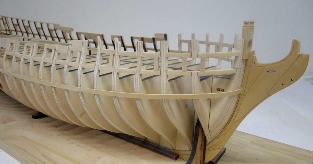
I have finished planking the starboard side up to the sheer. I will start on the port side this weekend. As you can see now, the wales and black strake are much darker than the wood above it. That was done on purpose so I could easily identify the wales when I add the second layer. Having said that, the Alaskan Yellow cedar is really nice stuff for working this large. I like the color and its easy to work with. This is the largest model ship I have seen made from Yellow cedar. This will be a great test of how versatile and useful it is for ship modeling. Chuck
- 1,784 replies
-
- 42
-
-
- winchelsea
- Syren Ship Model Company
- (and 1 more)
-
No I dont sell the wood or have any of that material. Its pretty impossible to import other than by commisioning the cnc carvings. Damn near impossible to import raw wood from China.
- 1,784 replies
-
- 3
-
-
- winchelsea
- Syren Ship Model Company
- (and 1 more)
-
As good as your first version looked, this one is even better. It really looks clean and well crafted.
-
Neither...They are some weird Asian Boxwood. Its what they use to make all of the little carved sculptures you can buy on the web. It has no grain pattern at all and carves like butter. But it is more yellow than Castello or even European box.
- 1,784 replies
-
- 3
-
-
- winchelsea
- Syren Ship Model Company
- (and 1 more)
-
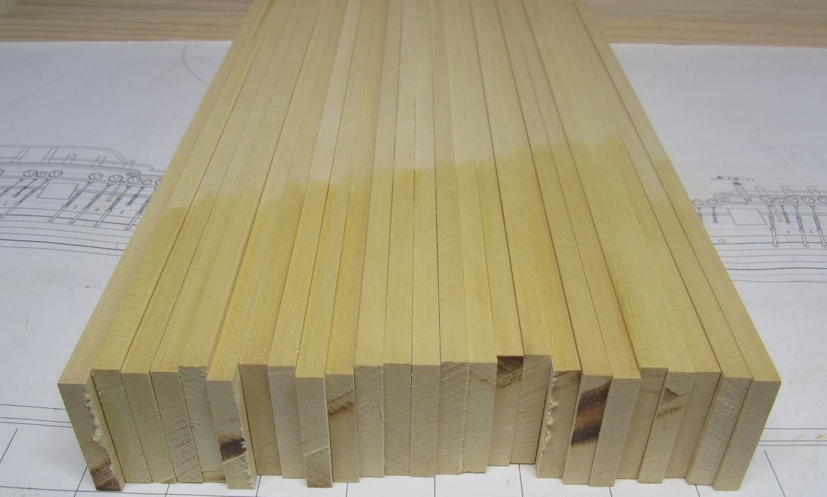
Yes they are the milling marks from the monster bandsaw I use to mill sheets from those larger bricks of wood. But you dont see any on the wide sheet I milled. What you do see on the smaller 2" wide sheet is the grain pattern.......so when you rip the strips from this smaller sheet the "important" side of each strip wont have them.
- 1,784 replies
-
- 4
-
-
- winchelsea
- Syren Ship Model Company
- (and 1 more)
-
Leopard did a great job showing what I was describing......and no.....edge bending is fine either way. But the face of your strip is smooth and grain-free on your model.
- 1,784 replies
-
- 3
-
-
- winchelsea
- Syren Ship Model Company
- (and 1 more)
-
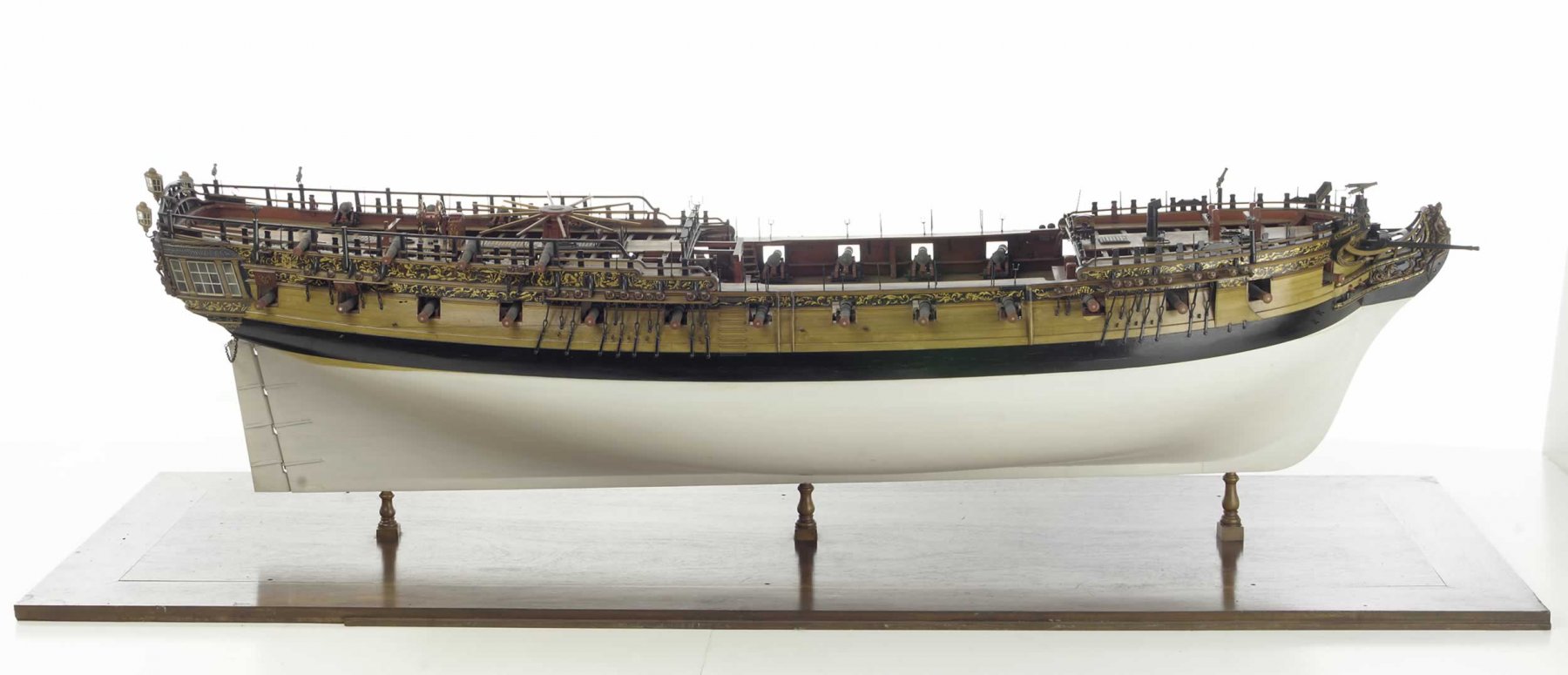
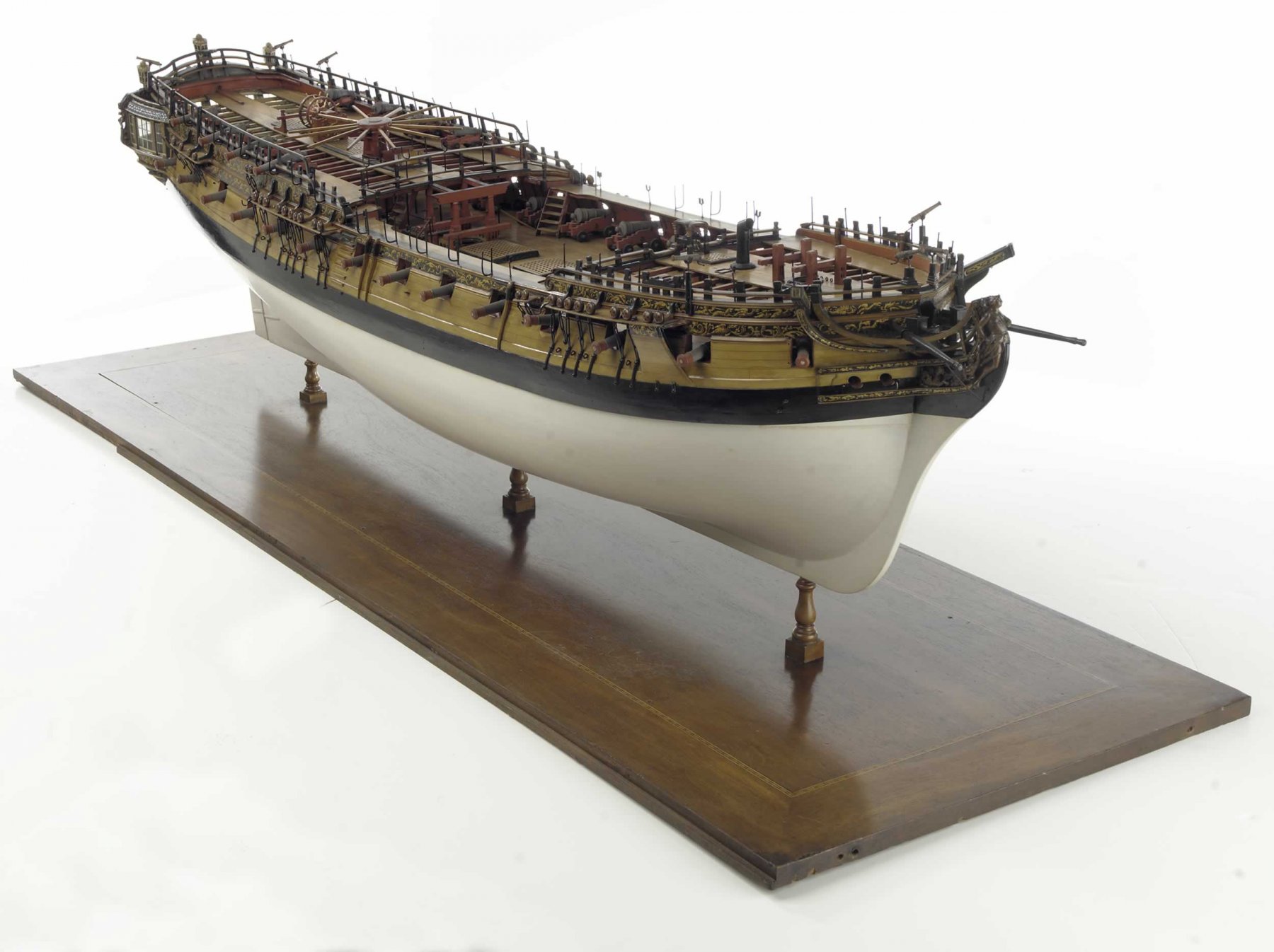
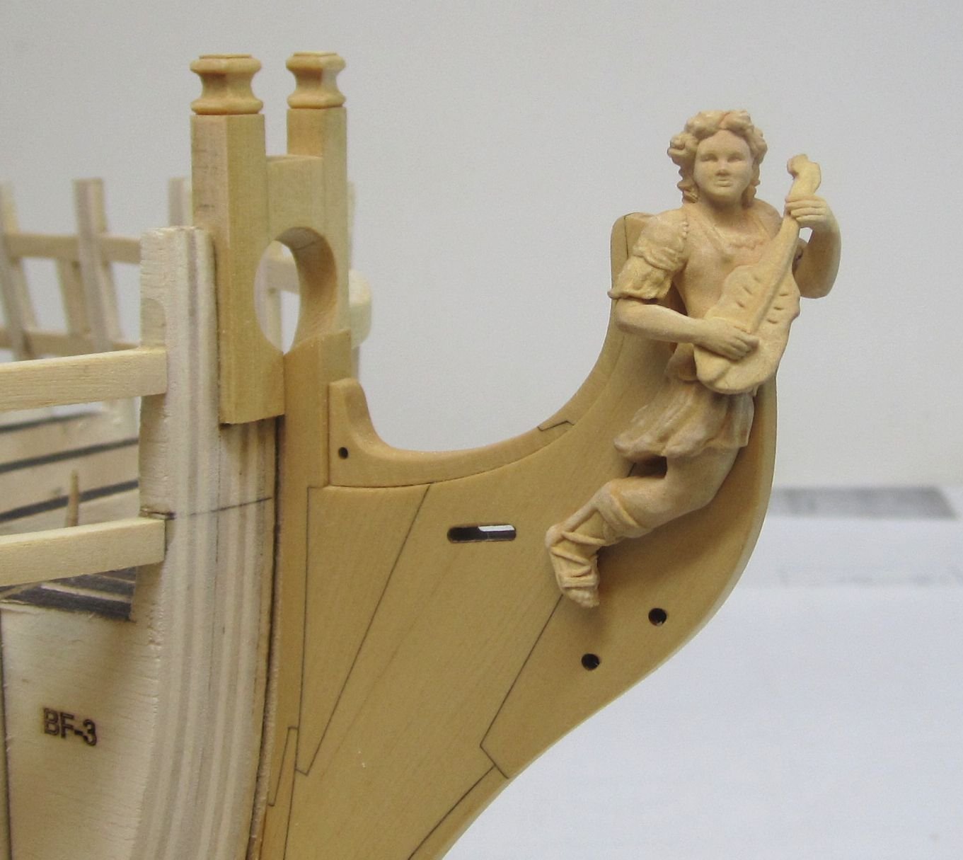
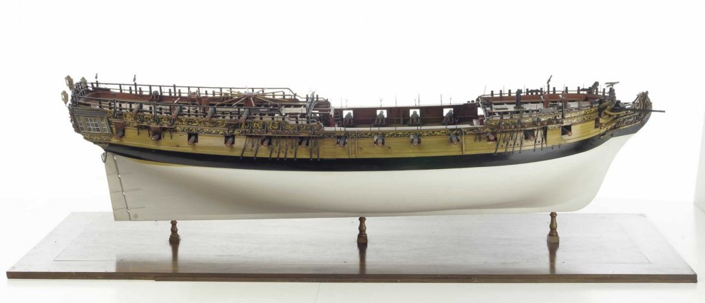
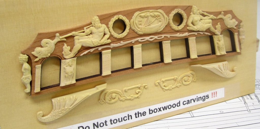
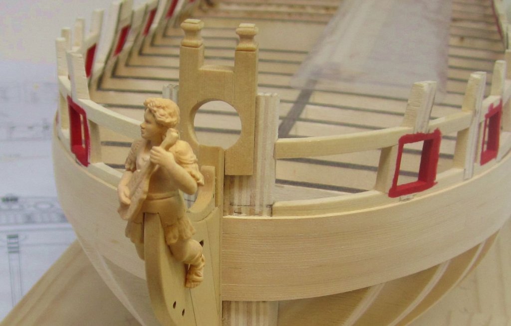
thanks guys....Rusty, I am just waiting til I finish planking a bit more. Its been a long time since I had to cut around so many gun ports. The Starboard side is a third of the way complete. You can see the five strakes of the wales and black strake which are darker. This first layer was done this way on purpose so I could make sure that I put the second and final layers on the right strakes. Also....the black strake can be left bright and unfinished or painted black along with the wales. In this case the wales on the Winnie are so wide I think it would look a bit much. So I will NOT be painting the black strake. I am using other contemporary models like the Amazon as inspiration for this. See below. Imagine if you can if the black strake was also painted black on the model below. It would be too wide and look over-bearing. Dont forget to click on those pics of Amazon.....they are quite large and quite a treat to see this magnificent model up close. I have these handy as inspiration while working on my model. Oh I also made this mock up of the other carvings to display at joint clubs. I know its not the best picture....but I thought I would post what all of the other carvings will look like. These dont have any finish on them.


- 1,784 replies
-
- 39
-
-
- winchelsea
- Syren Ship Model Company
- (and 1 more)
-
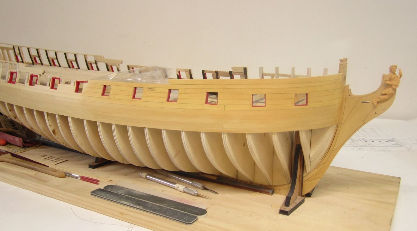
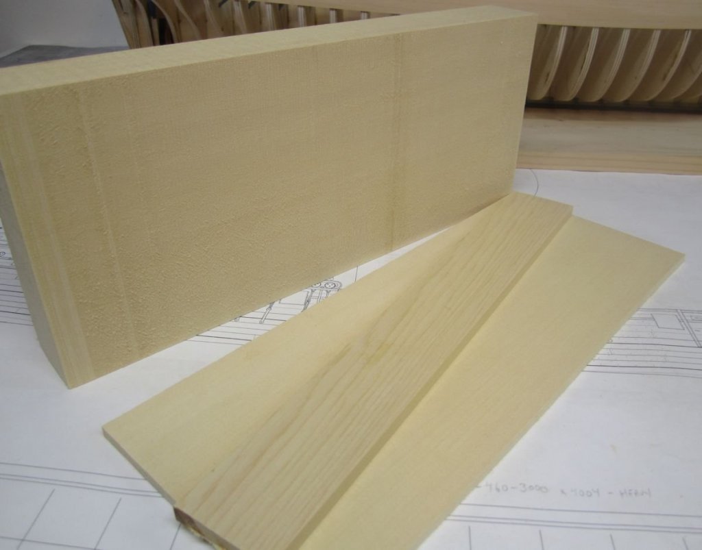
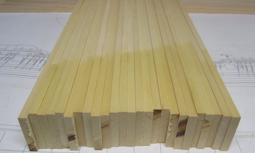
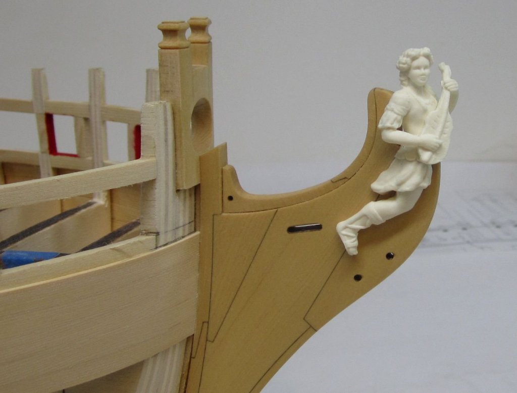
As I am about to start planking above the wales, I wanted to spend a moment talking about milling planks. Specifically Alaskan Yellow cedar but this is true for most woods. I will be offering a cherry version of this project and this is also true of cherry wood. Like everyone else, I cut my sheets from larger billets of wood. Below you can see one of the these "bricks" of yellow cedar lumber. It is a 2 x 6 that has been cut to 15" long segments. In that same photo you can see a very large 1/4" sheet that was cut from the side of the brick. It is pristine with no visible grain and the surface quality is beautiful which is what you want in a sheet of wood. On top of that 5 1/2" wide sheet is a 2" wide smaller sheet literally cut from the same brick shown. It was cut from the top of the brick instead. Notice the ugly grain pattern that is quite evident and if you were to get this sheet you would not be a happy camper.....BUT When I rip planking strips from a 1/4" thick sheet of wood, I dont want to use that wider sheet. The useable visible face of each plank would have the ugly side showing when you used it on your model. You would absolutely see the grain and it would probably not bend the same way......so I actually use the two inch wide boards to cut all of my planking strips from. I keep a steady supply on hand and even use wipe on poly on a portion of the "good" edge that will become the planking you see on the hull. This makes it easier to pick wood that is the same color so all of the planks will match on your hull. See the photo below which shows a portion of my 2" wide planking stock ready for milling. Whenever I cut the planking strips for a Cheerful package they are cut from these 2" wide pieces rather than the really wide sheets. Its the proper way to rip planking strips. I know that most people do the math in their head and figure they will get many more strips from the wide sheet....BUT...it will have a really noticeable negative impact on a well-planked hull. I will soon add a category in my store to allow folks to buy these 2" sheets rather than get the really nice wider sheets when they need planking strips. Most may be surprised and disappointed when they get the narrower boards until of coarse they start ripping strips from them which will be pristine and beautiful as you can see below. I can get 20 strips 3/64" thick from each of these with a blade that has a .30 kerf....I hope this was helpful and insightful to those of you who might not be familiar with this or may be thinking of getting a Byrnes saw to mill your own planking strips. I will call these " Planking Stock for milling planking strips" in my online store. Almost forgot....here is what that snow white resin figurehead looks like once I applied some color to it. I used three colors of weathering powder only. There is no paint on this. The color matches the wood very closely and I will be detailing how you can achieve this result later on... Now its time to start planking.
- 1,784 replies
-
- 48
-
-
- winchelsea
- Syren Ship Model Company
- (and 1 more)
-
looks good to my eye. You are miving right along.
- 160 replies
-
- 2
-
-
- cheerful
- Syren Ship Model Company
- (and 1 more)
-
That is probably the trickiest part of the build. Well done.!!!!
-
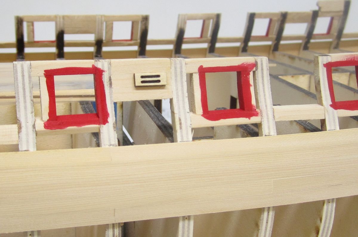
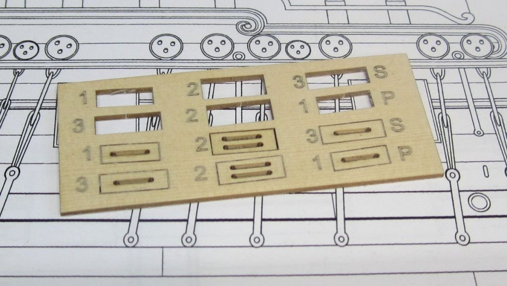
The port openings were painted red in preparation for planking up to the sheer. Then I added the fixed blocks. The outer shells are laser cut and etched for convenience. You could round off the sheave and then glue them into position. I used a pencil to darken the sheave. There are three per side. The extra ones on the sheet are actually for the inboard side after I fair inboard. These will be glued on the other side before planking as well. To help register them properly, I drilled the holes on either side of the sheaves straight through. It will make it easy to match the inboard shell up to its mate. But you must be careful to drill through the bulwarks straight ......not angle it as you go. That would mean a misalignment for sure. One other note......I received the test cast for the figurehead today in resin. It is just white so it may be hard to see the details but it is a really good cast. It matches the original exactly and is in two pieces just like the wood version. You can hopefully see the comparison so now everyone will have a choice between the more expensive cnc wood carvings and the resin versions....which are still not very cheap. The original wood carving below... Chuck


- 1,784 replies
-
- 36
-
-
- winchelsea
- Syren Ship Model Company
- (and 1 more)
-
Nice restart Jeff. Before you know it you will be right back where you were. Just keep it away from small children this time!!! 2nd time is a charm. Chuck
-
thanks fellas, next I will be painting the port linings red and adding the fixed blocks along the hull. Then i will continue planking up to the sheer. Chuck
- 1,784 replies
-
- 5
-
-
- winchelsea
- Syren Ship Model Company
- (and 1 more)
-
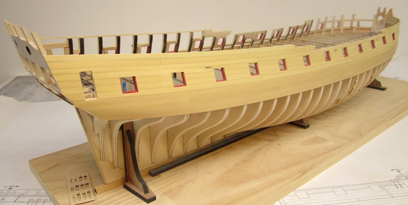
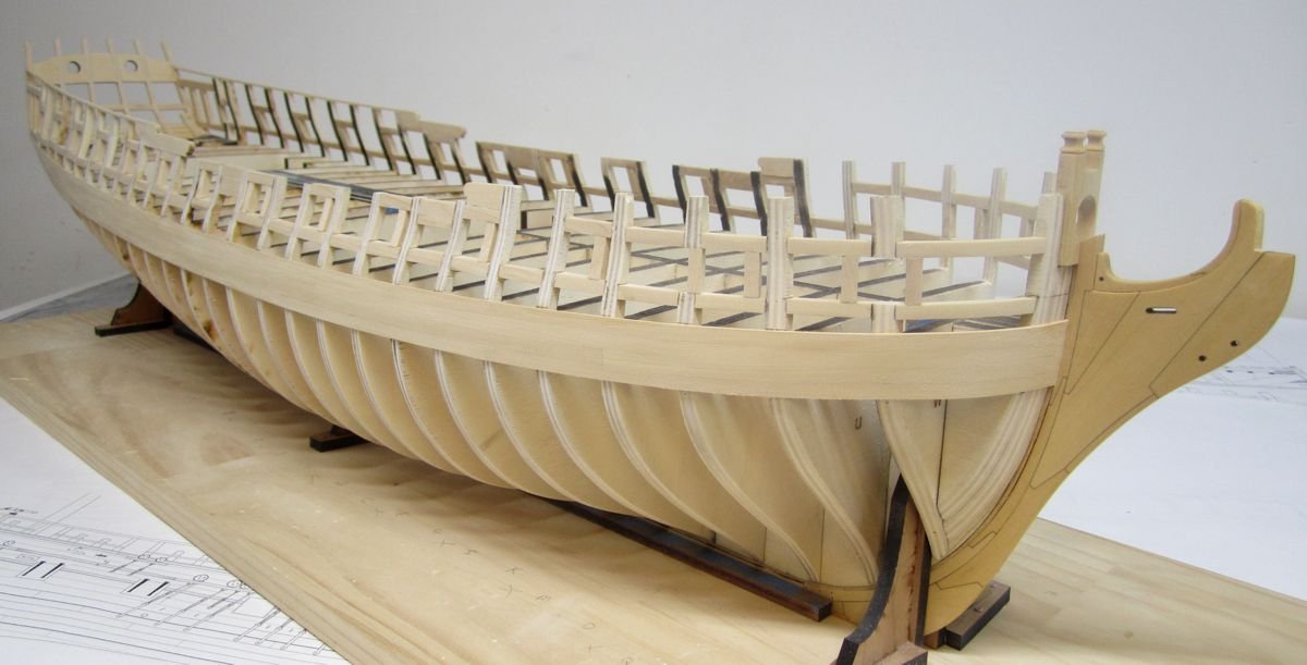
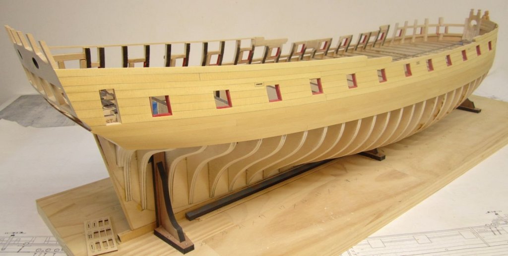
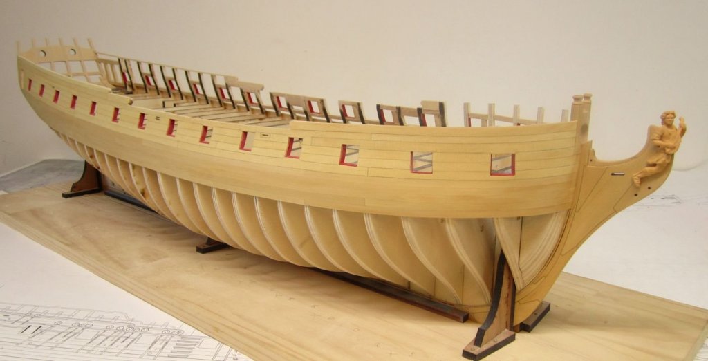
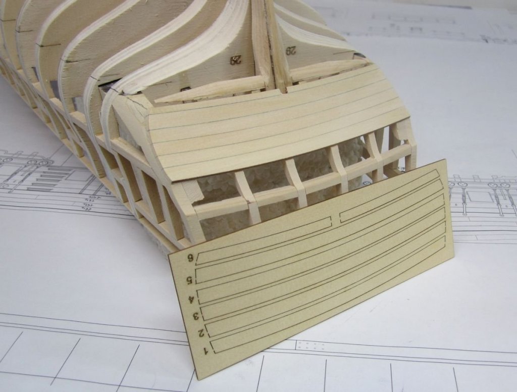
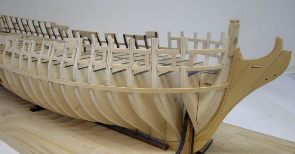
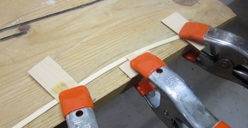
The lower counter was planked with laser cut strakes. One thing I noticed on other projects is that some folks find it tricky to bend or cut these strakes to the proper curve. This is very important because it determines the shape of the upper counter and thus the quarter gallery etc....and it just compounds from there. So these strakes are laser cut. I started with the top of the counter and worked my way lower where the final pieces were placed on either side of the stern post. This will be covered over with a frieze but I added simulated caulking anyway. I wanted to test how much would be used elsewhere. Running a pencil along one edge of the joint was perfect. The wales were stated and this is another crucial moment. The run of this first plank will determine a lot. The etched marks and references I made after running the batten were used to line up the bottom of the first strake. I added this first strake with the hull upside down using 7/32" x 3/64" strips of cedar. I still made adjustments after I finished the strake to try and get a smooth run. I dont care about using a pencil to simulate tared seams on these. This is just the first layer. I used the plans to determine where the butt joints fall (4 butt shift). I added this lower wale strake on both sides before working my up to complete them. All four strakes for the wales are 7/32" wide. Then it was just a matter of adding three more strakes above that one. Note how there is no caulking but each strake was carefully added so the seams were nice and tight. I did have to pre bend the lower two strakes of the wales at the bow edgewise. This was done as an alternative to spiling the curved shape needed at the bow. Its the only way you will get the planks to lay flat against the bulkhead edges. I used a hold-down jig in the center as the pivot point which has a slight curve to it. Then I clamp the plank on either side after bending it as needed. Note the scrap wood pieces used to help prevent the soft cedar from denting. As usual I uses a hair dryer on the hottest setting to heat up the strip and then let it cool down before removing it. The curve you need is very slight. No need to over bend these yet. The first layer of wales on the starboard side are completed...all four strakes. Now to complete the other side. Chuck


- 1,784 replies
-
- 51
-
-
- winchelsea
- Syren Ship Model Company
- (and 1 more)
-
Wonderful job on the model and a much deserved Gold medal. Congrats!!! What a fun way to end a build log!!! Chuck
- 449 replies
-
- 2
-
-
- sultana
- model shipways
- (and 2 more)
-
She looks absolutely beautiful....you did an amazing job on the kit. I hope you really had fun with it. Its not a really long project and that is what makes it fun to build.
- 32 replies
-
- 4
-
-
- medway longboat
- Syren Ship Model Company
- (and 1 more)
-
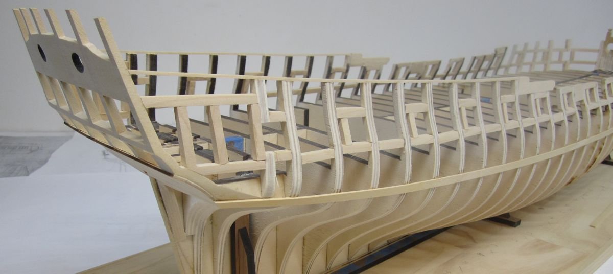
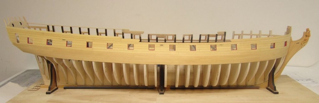
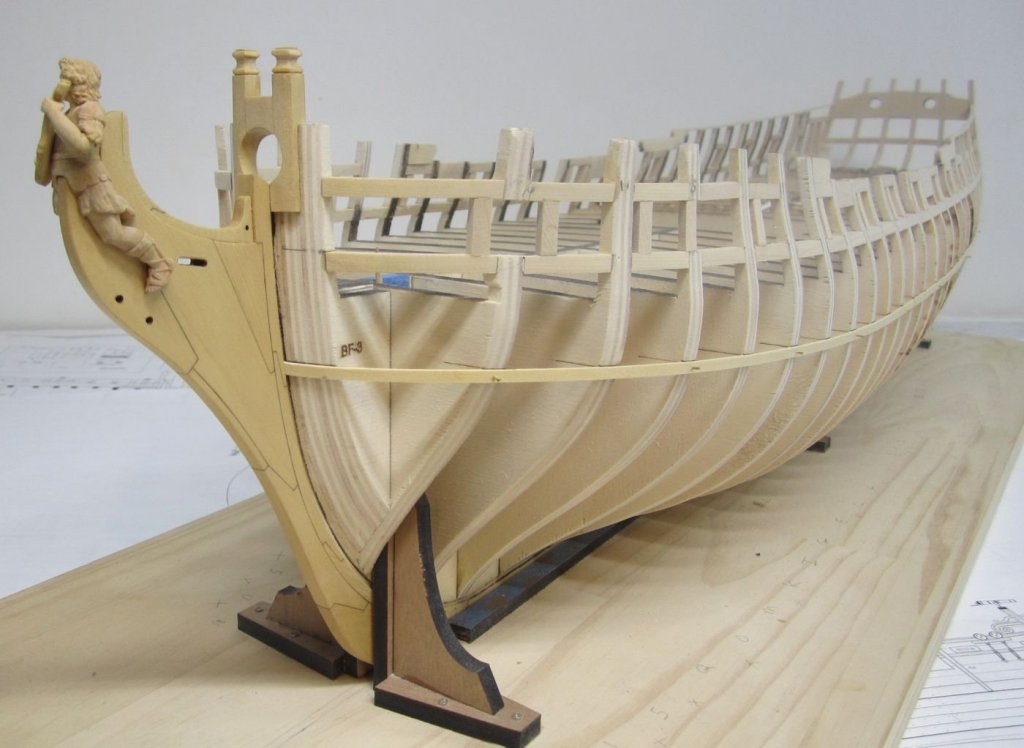
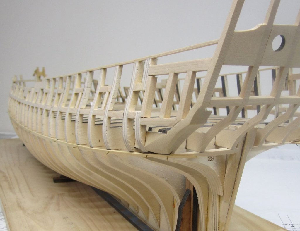
The last thing I did before leaving was to prepare for planking. This entailed the usual batten placement. I cant stress enough that this is probably one of the most important procedures for any ship model project. The batten represents the run of the wales and if there are errors and dips and waves with your placement it will impact countless aspects of your project later. Not just the run of your planking but also your placement and angle of the quarter galleries, your curve of the sheer, your placement and shape of the headrails. So take your time with this. The top of the batten strip represents the BOTTOM of the wales. I followed the laser etched reference lines on the bulkheads but this is just a start. Some of these will be "off" for various reasons. So once you have the batten in position you should eyeball it from as many different angles as possible to correct any issues. You want a nice smooth run. Note where the batten intersect the stem at the bow and its proximity and location to the scarf joint on the stem. There is a gentle "s" curve to the run of the wales at the bow and this can be tricky for folks who never noticed it before. The batten is nailed temporarily in position. At the stern, it could get tricky also. Note where the top of the batten rests on the lower counter. For those of you who may build this model, the top of the batten falls right in the middle of stern frame "D" as if you ran a line directly down the outside edge. As soon as I get back I will start planking the lower counter. The lower counter planking will all be laser cut and pre shaped. There will be six strakes of 1/4" planking. Next stop is the beach with where I will sit with a drink in my hand ...maybe even with one of those fancy little umbrellas. See you when I get back. Oh and the online store for Syren is now officially closed until I get back.
- 1,784 replies
-
- 43
-
-
- winchelsea
- Syren Ship Model Company
- (and 1 more)
-
Bob That looks great!!! You made it look easy. You are home fee now. The rest of the project is pretty straight forward. I hope you are having fun with it. Chuck
-
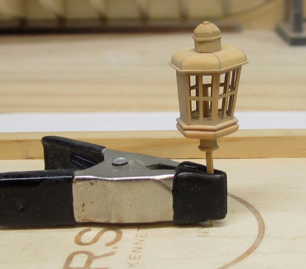
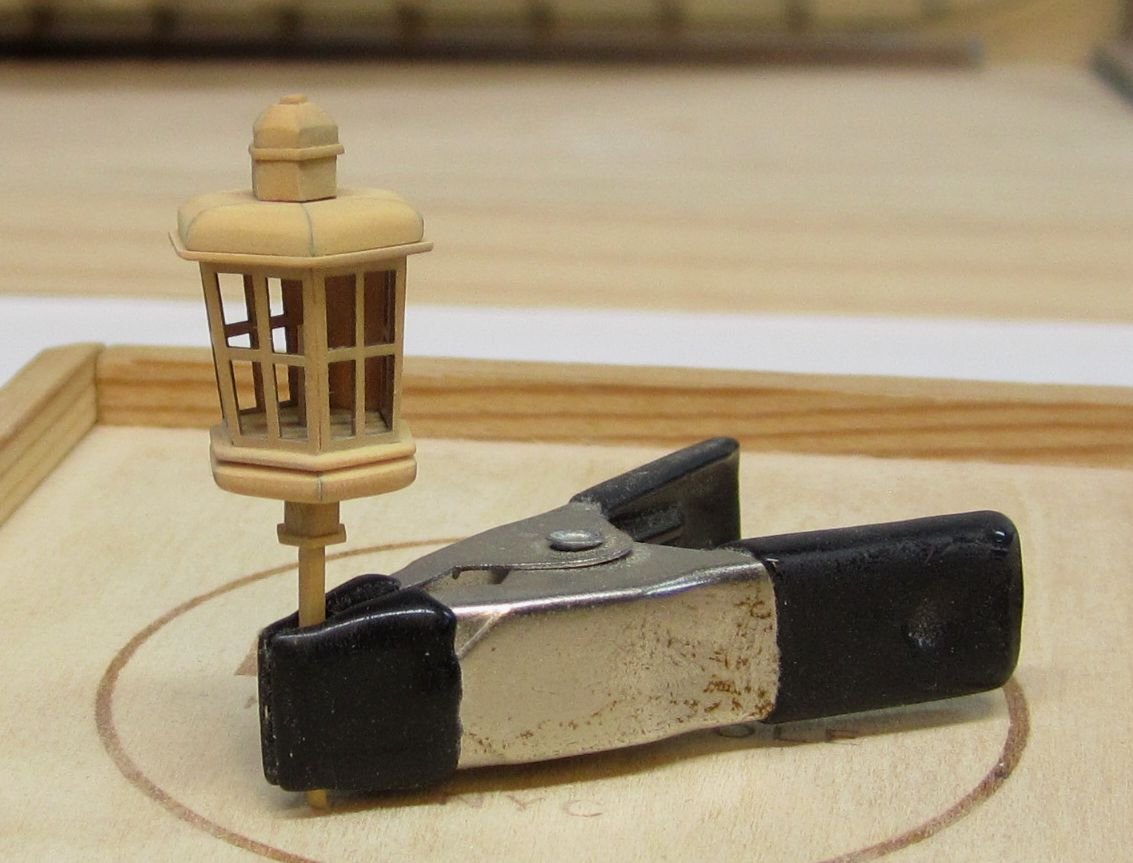
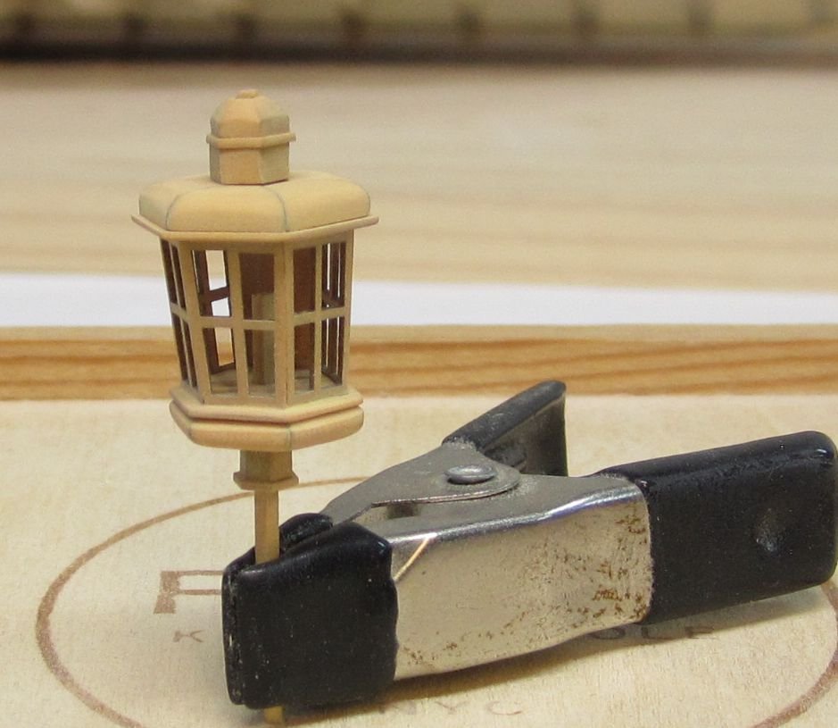
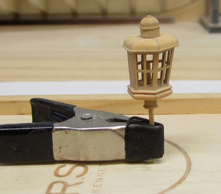
Revisiting the lantern... As I prepare to leave for a short vacation, I decided to wait until I get back to start the planking. I want to be fresh and rested before I start that. But in the meanwhile, I have been working with Mike on some fittings and have revisited the lantern. I wanted to try and make an all boxwood version for the larger Winnie. So I redesigned some pieces. This would address some end-grain issues and also account for slightly thicker windows etc. Not that much thicker however. I wanted to avoid laserboard all together to eliminate the need to paint any pieces because unless you are an expert painter the lantern could look sloppy. To avoid this I began by thicknessing some boxwood sheets for laser cutting down to .015". I was worried they would be too fragile and the windows wood break along the end grain. But to my surprise, if they are handled carefully they hold up quite well. The prototype is shown below. The inside of the lantern will of course be painted red with a white candle in the middle. I didnt even insert the acetate windows. I am just proving out the new design changes to see if everything fits. I havent put the hardware on the door yet (hinges and handle). I will do that when I build another and rewrite the instructions. But it came out rather well. I am quite happy with it but it is an advanced little mini-kit. You must go slow and sand everything very carefully to ensure a tight fit of the parts while keeping it clean and neat. This prototype took me about 5 hours to assemble. I havent drilled the vent holes in the top yet either. These small details will be added on the next one I make. Wipe on poly was applied as the finish. My guess is the next one which I will actually use on my model will take longer as I add the other details and paint the interior etc. No photoetch or laserboard.....all boxwood this time around!!! The pictures are a bit misleading because this is still a very tiny and complex fitting to build. Chuck


- 1,784 replies
-
- 43
-
-
- winchelsea
- Syren Ship Model Company
- (and 1 more)
-
Yes it is a soft wood. You need to be careful and treat it like you would basswood. Although it leaves a real sharp edge and doesnt get fuzzy. The end grain also doesnt darken much when you apply a finish. You just need to be careful and cut your nails. Chuck