DONATION DRIVE - SUPPORT MSW - DO YOUR PART TO KEEP THIS GREAT FORUM GOING!
×


Chuck
-
Posts
9,693 -
Joined
-
Last visited
Content Type
Profiles
Forums
Gallery
Events
Everything posted by Chuck
-
 excellent model!!! You did an incredible job on her. That will be a tough act for anyone to top and should serve as a great guide for others building the kit!!!
- 242 replies
-
- 3
-

-
- syren
- model shipways
- (and 1 more)
-
Actually if you dont mind the look of an admiralty style model or just a planked hull model, 1:48 is my scale choice. The low but long cases are not an issue to display. Having at least one in your collection is a must in my opinion. The experience of building a larger frigate is something I think everyone should consider at least once. I used to think the same thing actually but now that I have started on one, the build experience is far more enjoyable. I am fortunate to have started a 32 gun frigate in 1:64 many years ago and it is incomplete. But I have just restarted the project in a larger 1"48 scale. The build experience is very different and much more enjoyable when I compare the two. Looking back at the smaller version I wonder why I even attempted building it....it makes for a much more tedious and frustrating experience. Although I know a few people who are building frigates in 1:96 scale. I dont think I would enjoy that building process at all. But yes, displaying it would be easier. If I knew that I was going to spend possibly years building something, I would want to enjoy the process with as little frustration from the small parts as possible. I would rather think about solutions for their eventual display rather than suffer through two years of building something tiny. Maybe thin the heard a bit to make room for the larger model. Also, your skills probably improved over time and culling out your earlier models built to a lesser degree of craftsmanship is something I dont mind doing.
-
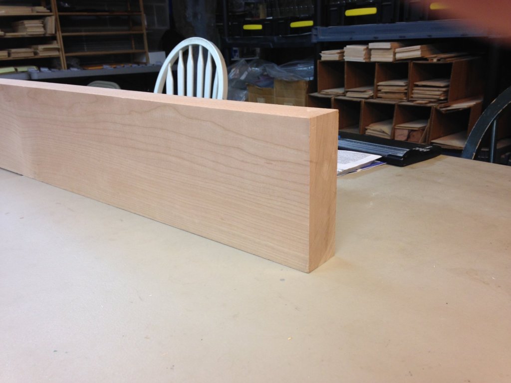
I also just got a wonderful batch of raw cherry lumber. I thought I would show you guys. The Winnie will also be available in cherry. From this very cherry board. Its really nice stuff and some of the best I have bought. Very clear cherry with little to no gum pockets and sap spots. Once I get some of this milled along with a few more boards of cedar I will actually start laser cutting parts for the first two Winnie parts. This way I have a bunch in stock when I am ready to launch.
- 1,784 replies
-
- 23
-
-
- winchelsea
- Syren Ship Model Company
- (and 1 more)
-
I forgot I had the pictures from seven years ago of the smaller version in boxwood.....it is freaky looking at them right next to the newer version. I made several small changes in the design and appearance but they look like they could be pictures of the same model even though the wood is completely different.
- 1,784 replies
-
- 8
-
-
- winchelsea
- Syren Ship Model Company
- (and 1 more)
-
Case in point about the similarity between Cedar and boxwood. Mike hasnt applied any Wipe on Poly to his Winnie yet. That will be a really good comparison. Hopefully in a Couple of weeks. But to illustrate the color and texture between these two fine woods I can post the images below. The first smaller (3/16" Boxwood) version of Winnie from seven years ago is on the bottom. The Winnie in Cedar clearly has a richer, deeper warm tone. But they are very similar. When mixing some boxwood for the finer details, it blends so well that is is so difficult to tell where the boxwood was used. This helps me exploit the use of boxwood on the thinner more delicate parts of the model without them sticking out like a sore thumb. They will just blend in perfectly.

- 1,784 replies
-
- 27
-
-
- winchelsea
- Syren Ship Model Company
- (and 1 more)
-
My longboat is already cedar. The 1/2" scale kit. I have 3 in stock. Some elements are better suited for other woods however. I am certain the ships wheel could be made out of cedar. The same is true for the lantern and a few other things. But having said this, the color difference can barely be noticed. In fact, in many cases you could never tell the difference between box and cedar on the model. If you look at the Medway Longboat, the molding and a few other elements are boxwood rather than cedar. You cant tell and the boxwood is best suited for scraping molding. I plan to use it for such details on this model too. For example....the molding, ships wheel, stern and quarter gallery windows. The beauty of cedar is that it is not so different than boxwood that it cant be mixed on one project without being noticeable in order to take advantage of the best qualities of each of them. The Winnie will have a longboat and a Pinnace. These will be afded and designed much later. They will be very simular ti the two ships boats I made for Confederacy.
- 1,784 replies
-
- 7
-
-
- winchelsea
- Syren Ship Model Company
- (and 1 more)
-
grumbacher mars black....thought i would try something new. Works fine and really cant tell any difference from Windsor and Newton I used to use.
- 1,784 replies
-
- 4
-
-
- winchelsea
- Syren Ship Model Company
- (and 1 more)
-
Thank You very much for saying....The wales look odd otherwise. The wales were just painted by hand. Nothing special ....no dye or pickling. I used black acrylic paint. The wales were painted before the black strake was glued into position....so no need to be too careful with the top edge. The black strake which was left natural covers any errors and gives you a nice clean edge. I am a gluten for punishment... I could have painted the bottom edge before gluing it, but I just painted the wales after I sanded them very smooth and filled every crack. The trick is just to go slow and use many many coats of thinned paint. Sand with 400 grit before the last few coats. I did buff to a dull sheen. I am sure many more coats and additional sanding will be done before the model is completed. Chuck
- 1,784 replies
-
- 9
-
-
- winchelsea
- Syren Ship Model Company
- (and 1 more)
-
When I finish planking her. That is when I will release the starter package and second installment. I just want to get well ahead of the crowd. It will be available in Alaskan Yellow Cedar and Cherry. Depending on what you like better .....both wood choices will be available. I would love to see a cherry version built.
- 1,784 replies
-
- 9
-
-
- winchelsea
- Syren Ship Model Company
- (and 1 more)
-
Originally that is how I intended to do it. But I thought it would be a nice change to have guns on both sides. I would also be able to skip making and adding all of those knees. Nobody would ever see them. LOL...but we shall see. I may change my mind from now till then.
- 1,784 replies
-
- 5
-
-
- winchelsea
- Syren Ship Model Company
- (and 1 more)
-
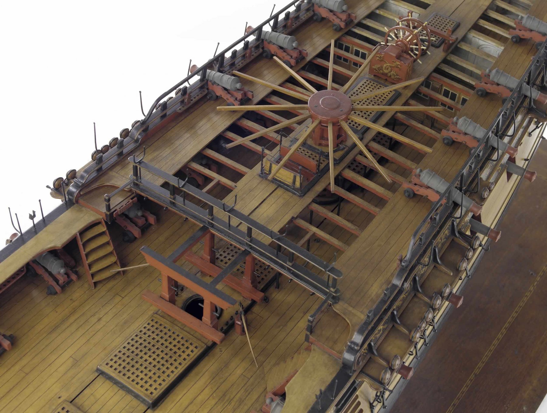
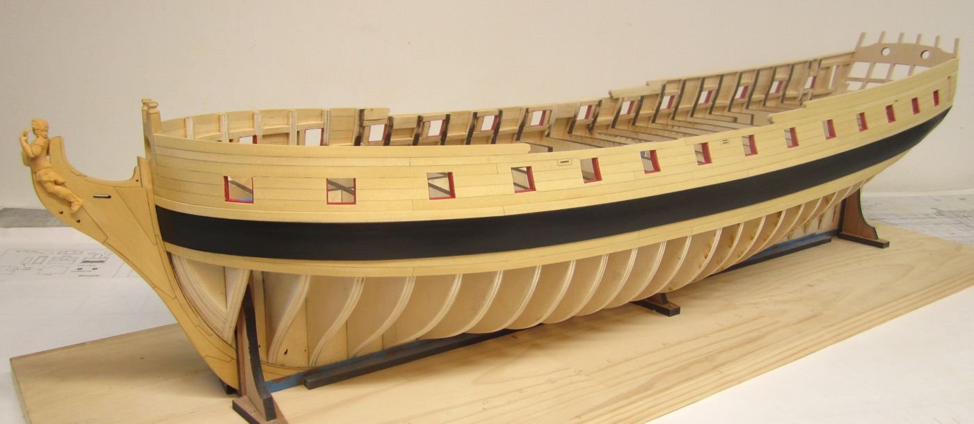
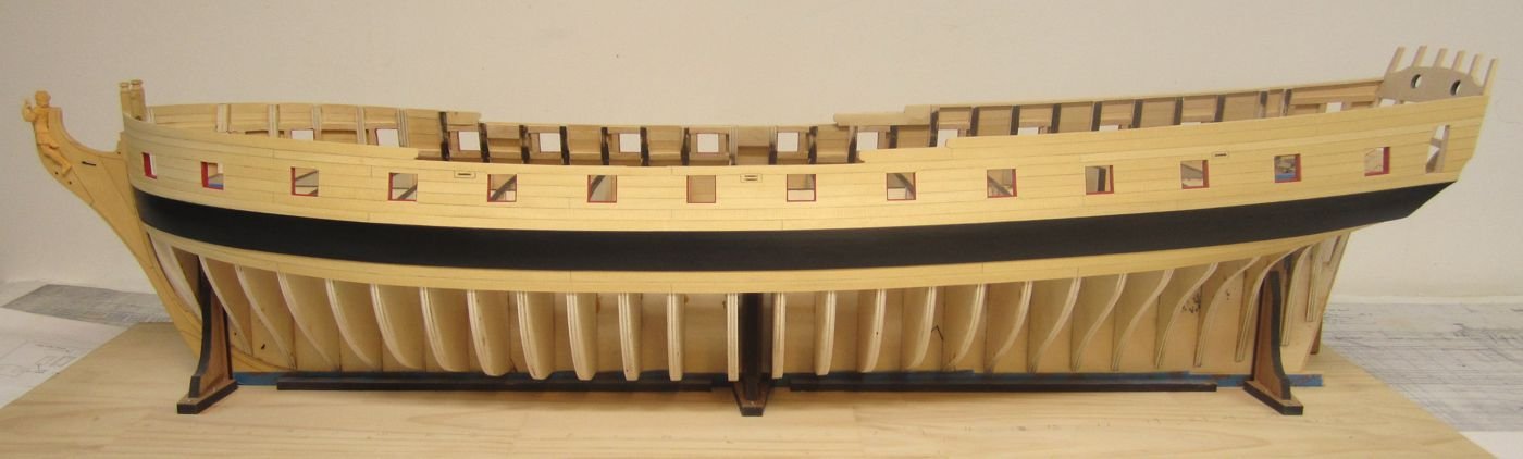
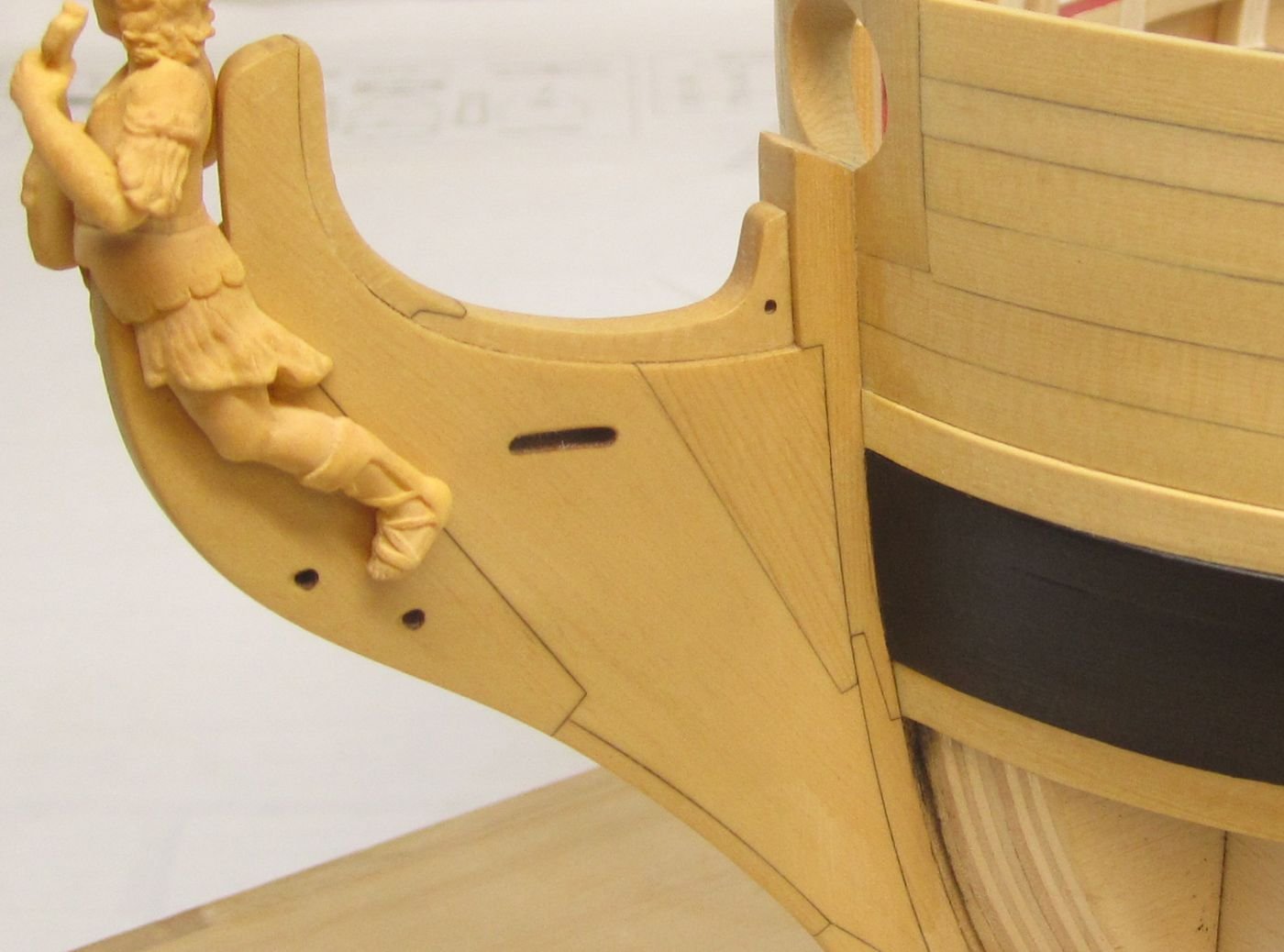
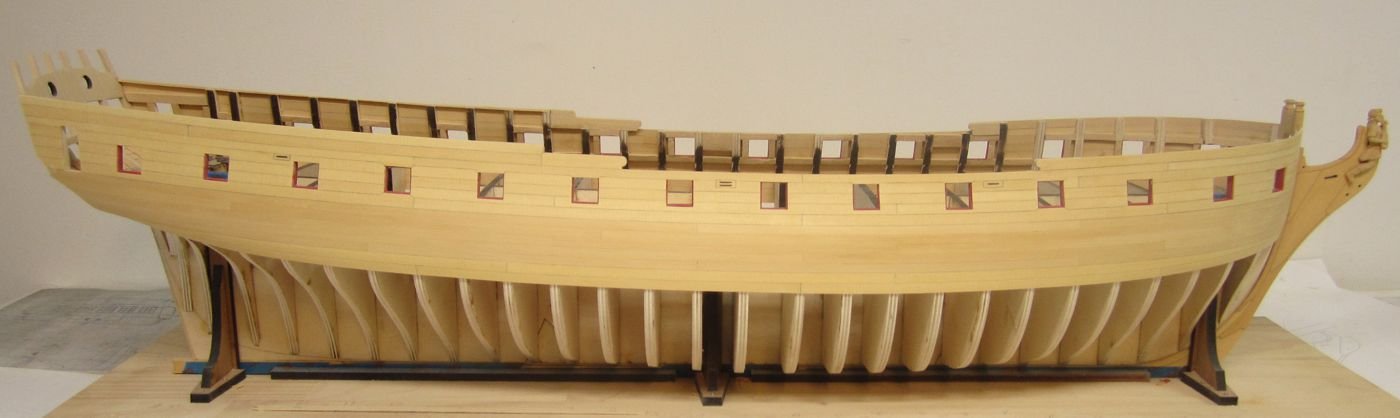
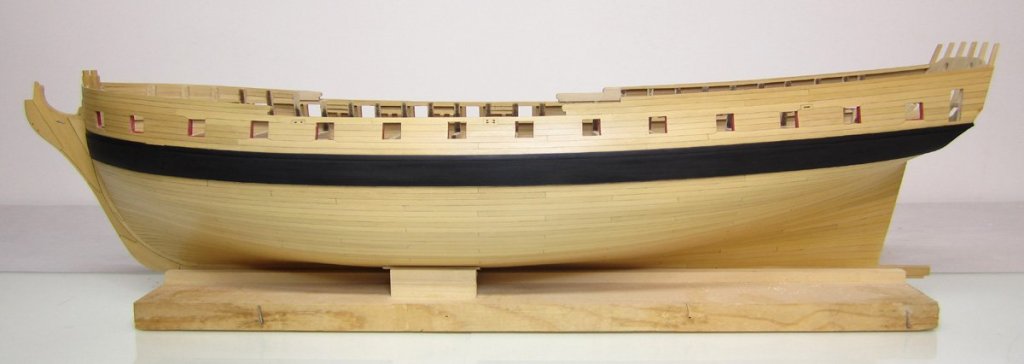
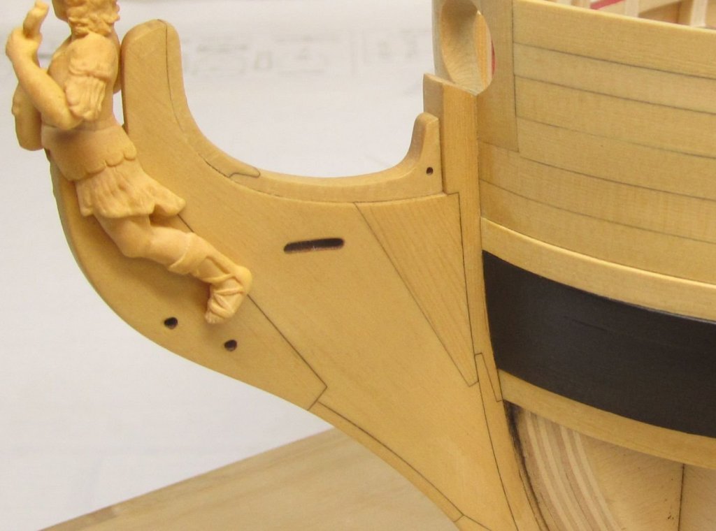
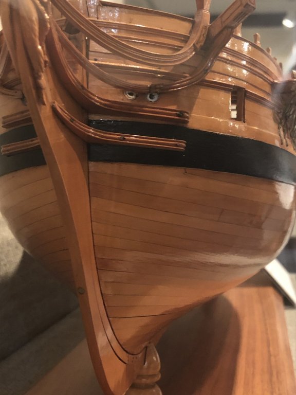
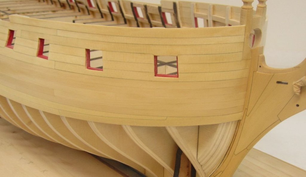
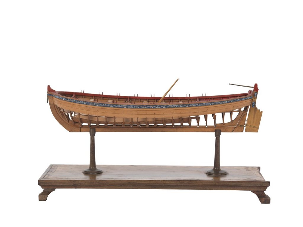
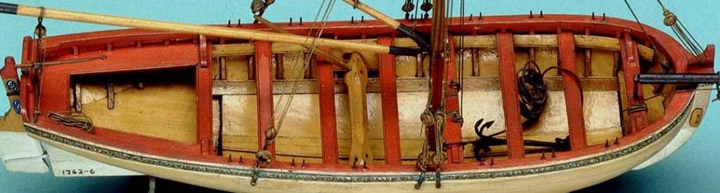
Happy 4th to all my fellow countryman.....☺️ I think I will spend this holiday working on the Winnie. With the drop planks completed, I could add the second layer of wales and the black strake. I used 3/64" thick planks for the wales and just 1/64" thick planks for the black strake. One thing I see a lot on kit models are the wales made really thick. They stand proud of the planking by 1/16". This was not the case usually and so the on this model the wales followed this actual practice. Here is a great example on this contemporary model from the same period. This is the Amazon....note the wales and how thick they are in relation to the planking. By the way..this is how I plan to show the quarter deck modeled with exposed beams...at least as of today. So here is the Winnie with wales and black strake completed on the port side. It makes the world of difference in its appearance. And one other thing I would like to mention. The wales and black strake would fit into the rabbet at the stem. It wouldnt stand proud as is shown on most kits and models these days. Its another typical oversight. To fix this, I simply reduced their thickness gradually up to the rabbet so it looks like it fits into the rabbet. I used a sharp chisel and some fine sandpaper. Comments and questions are always welcomed!!!


- 1,784 replies
-
- 34
-
-
- winchelsea
- Syren Ship Model Company
- (and 1 more)
-
Hows progress coming along? You are nearly all done with the model. I am looking forward to seeing the finished model. Its coming along fantastic!!!😃
-
No it is semi scratch....you can buy as much of the laser parts as you want. You must also buy the wood needed separately.... Either from me or from elsewhere. Its an a la carte build which in concept was presented this way so folks might be tempted to scratch some parts rather than buy the mini kits which are sold separately. Chuck
-
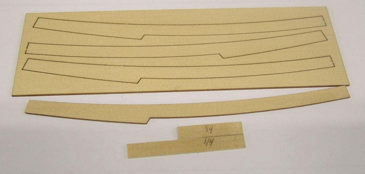
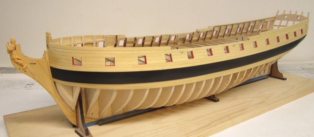
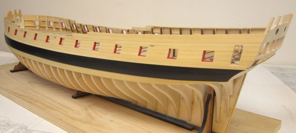
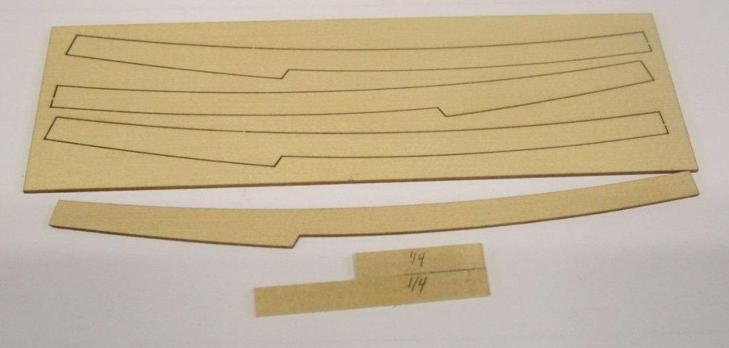
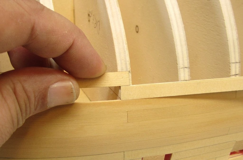
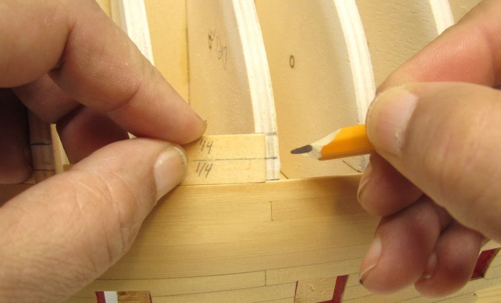
I finished planking the other side up to the sheer. With that completed, I would really like to add the second layer of the wales and the black strake. BUT...it just makes sense to add a few strakes below the first layer of wales first. To do this, we will need to make a drop plank at the bow. The drop plank essentially takes two strakes at mid ship and reduces them down to one strake as it enters the rabbet at the bow. I really good example of this is shown below on this contemporary model. A very similar drop plank was used on the Cheerful model as well. They are not that difficult to lay out and make. But having said this, I noticed that a few people building the Cheerful had some trouble making theirs. So to make that easier this time around, I laser cut the drop planks. Of course this may need tweaking to fit on other models of the Winnie. It will be almost certain that the planks above it will be added slightly different on everyone's model. But it should be very close. At the very least, it could be used as a template and new one cut to fit your model. You will notice another small tool in that photo above. Its two 1/4" wide planks glued together. This will be used as a gauge to mark the two strakes aft of the drop plank. Basically you should mark every bulkhead starting with bulkhead "Q" and work your way aft. Those bulkheads ahead of "Q" will have planks slightly narrower and tapered. Then I took the "tail" of the drop plank which will end on bulkhead "Q" and did a dry fit. I wanted to make sure a 1/4" plank would fit between the drop plank and wales....the "tail" of the drop plank is on the top in the photo below......then I checked to see if the plank fit and matched my tick marks. The drop plank was glued into position. I made sure that the "tail" ended where my tick marks indicated. Then I continued planking the two strakes and worked my way aft. Now I can finally add the second layer of wales and the black strake. That will be done next and after painting the wales this model should actually start looking like something recognizable as a frigate. Heres an overall view of the hull.....it will look much different once those wales are completed and painted. Once again heres that contemporary model.....note how the wales are black and the black strake is left natural. This is what I will be shooting for.

- 1,784 replies
-
- 43
-
-
- winchelsea
- Syren Ship Model Company
- (and 1 more)
-
I chose to model the Cheerful with her anchors stowed. You could however choose to show the model with anchor cable as others have done. Just check out some of the other build logs. Its a personal choice. I rather prefer not showing the anchor cables. Chuck
- 1,051 replies
-
- 4
-
-
- cheerful
- Syren Ship Model Company
- (and 1 more)
-
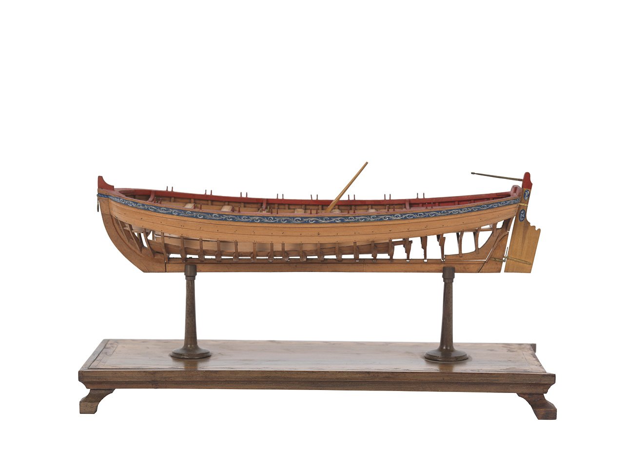
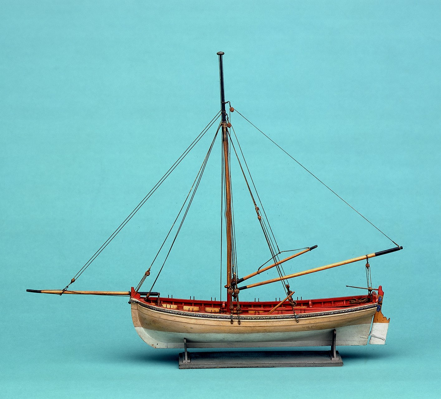
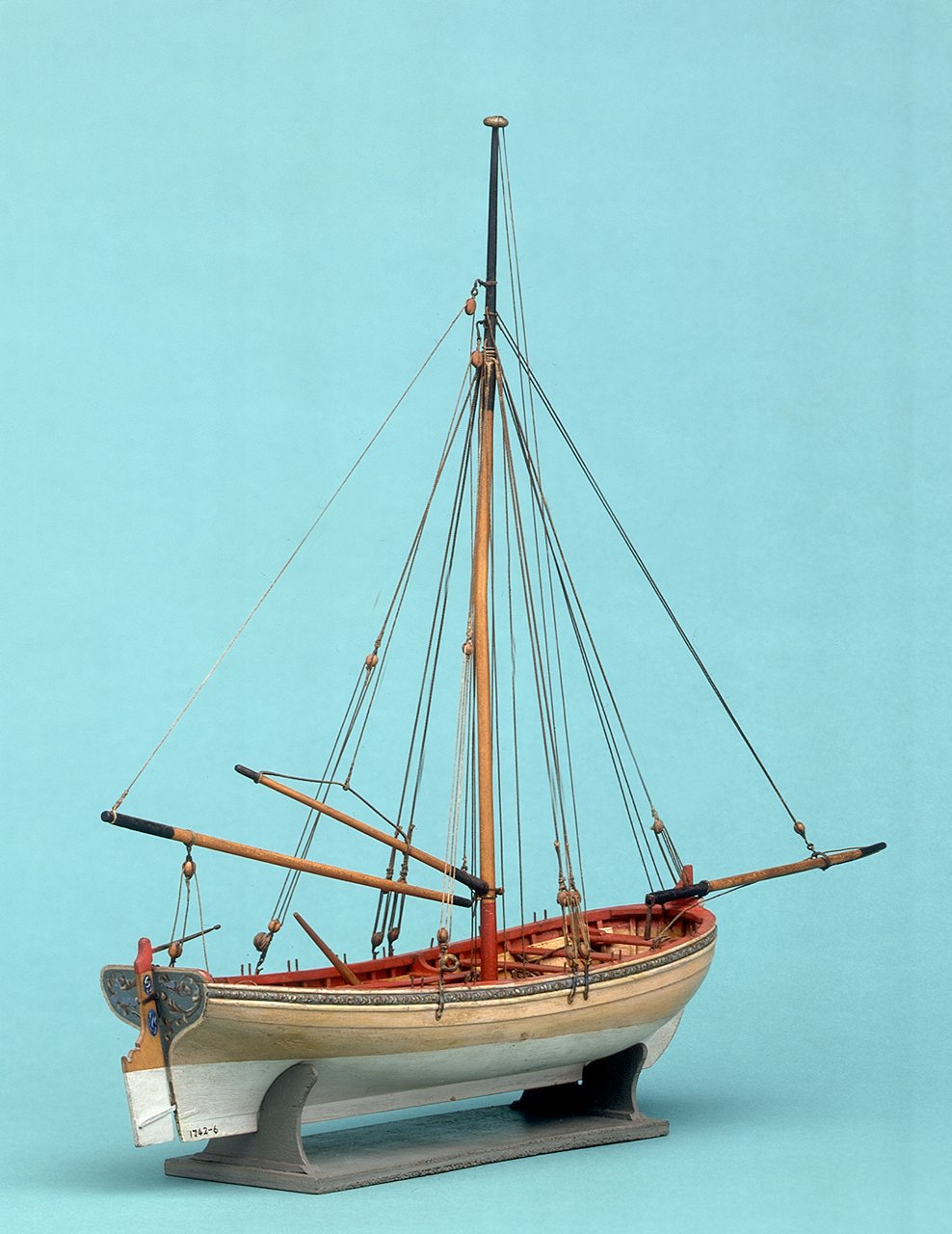
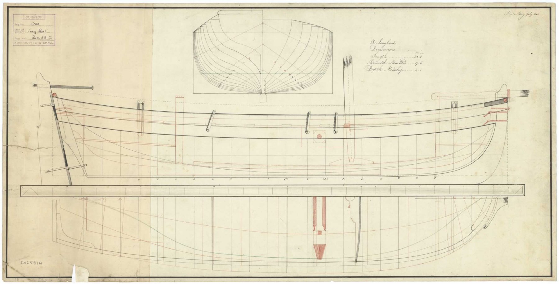
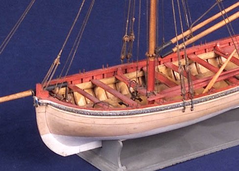
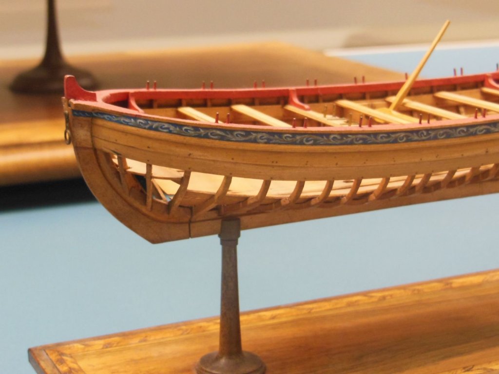
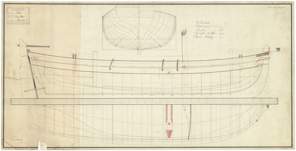
Remember guys....the best source for inspiration when building any model is to look at the contemporary sources available. If you want to see how it was done in reality.....really study the this model and others. Look at how the rigging is done...or how narrow the cap rail should be....or how thin the molding on the hull should be. This is in stark contrast to the kit. Look at the thole pins. Check out contemporary plans that show how a swivel gun stock was built. It was not just placed on top of the cap rail after widening it. Note on the plan I posted how narrow the cap rail is along with the swivel gun stocks that are attached to the inside of the bulwarks. Note where they are located on the hull. They are never on the transom. The aft pair are almost always shown where they are seen on the draft.


- 95 replies
-
- 4
-
-
- Model Shipways
- 18th Century Armed Longboat
- (and 1 more)
-
Its all lovely wood actually....but as you mentioned, there will always be variables. So after you rip your strips, they should be sorted for color. Those being darker for your tastes can be set aside for areas that you know will be painted. For example, the inboard bulwarks. Dont throw it away or discard it Mike....use it for the bulwarks. Chuck
- 607 replies
-
- 10
-
-
- winchelsea
- Syren Ship Model Company
- (and 1 more)
-
So happy to you start this kit...I will be following along. Have fun with it and dont hesitate t0o ask me any questions. Chuck
- 221 replies
-
- 1
-
-
- queen anne barge
- Syren Ship Model Company
- (and 1 more)
-
which blade did you end up getting for general ripping of boxwood? Did you get .030 kerf blade? That is the one I use mostly and you can hardly tell it apart from the Thurston equivellant.
-
Thank You!!! That is very kind of you to say.
-
Nice planking Ryland....only 4 more to go!!! Very precise joints. Its so nice to see so many clean well crafted longboats. Yours is an excellent example. Chuck
- 263 replies
-
- 1
-
-
- Medway Longboat
- Syren Ship Model Company
- (and 1 more)
-
For an example.....check out this Victory model which is in a beautiful case with table. If we as ship model builders tried to just buy this case and table for something we built it would cost more than what the model was sold for at auction. This model of Victory with additional cross section...... all cased up sold for just $400. It is a typical kit model nicely made with sails. Probably a Mamoli kit maybe. https://www.bonhams.com/auctions/24092/lot/392/ I do not mean to discourage you, developing a reputation and a following takes time. For example, I was offered $12,000 for my Cheerful not long ago. I didnt sell it however because its something that needs to be used as part of my business. I also sold one of my 1/4" pinnace models and 1/4" longboat models to a collector not long ago. They sold for about $3900 as a pair...all cased up. Not a huge sum but I made several others that I have decided to keep and how many of these can you have laying around. For the past 15 years I have just been giving my models away as I complete them....but my wife and kids want to keep a few of them now. The few models that I have sold were to people who came to me and specifically wanted to buy my model or have me build one for them. This is a very different situation and one I am grateful for. My guess is because I dont have much of a name as a frequent seller of models outside of the few who already know me, if I tried to sell one at a gallery or auction, I would get about $500 as well. Not enough to cover the cost of the case and materials. Unless you get someone who seeks you out personally and realizes the value of of your time and expertise and level of craftsmanship, selling them is hard. It takes work and a lot of time and help to get recognized as a ship model artist that commands decent money for their models. Chuck


-
It is just like trying to sell your paintings if you are an fine artist. Unless you have a track record of sales no matter what the quality of the art which shows some provenance, and you have a name and some following and notoriety in the industry, your art wont sell for that much. This takes years to develop and usually that means selling through galleries and auction houses. You will sell them at very low prices at first and then if your lucky.....you will gain a reputation and name for yourself and command higher prices. Its hard work to do this of course. I have seen good, master quality ship models sell for $30,000 and up...... and I have seen equally good work sell for $100's of dollars. Mostly because the builder doesnt have the name or reputation that commands higher prices. Its just the way things work. A gallery or good nautical reseller will do whatever they can to inflate your name and reputation so it does get more well known......in order to hopefully raise the asking price to match the quality of craftsmanship. If your work is less than master quality which should be left to others to judge in the industry, then most likely the model will be considered "furniture grade display" like the hundreds of models sold on Ebay and elsewhere. If you google any nautical auctions from various houses that sold models you will see some outstanding work with final sales prices in the hundreds. Some maybe around $1500 - $2000. Most if not all of them are not kits or kit-like. So without a photo it would be very hard to say. But I wish you the very best of luck. These can command a few hundred dollars and maybe a bit more as a decorative item at best. Its a tough racket to break into.
-
Really nicely done.....very clean work and your care in craftsmanship really shows. The joints are nice and tight .......excellent work.
- 87 replies
-
- 1
-
-
- medway longboat
- Syren Ship Model Company
- (and 1 more)