Chuck
-
Posts
9,663 -
Joined
-
Last visited
Content Type
Profiles
Forums
Gallery
Events
Everything posted by Chuck
-
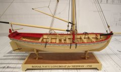
You can link to the Medway Longboat Group Project here.....Click Here This Group is still ongoing and you join if you would like to. Longboat Kits can be bought here. We encourage you to join and participate in the group. If you have any questions about this group before joining...please reply to this topic and ask away.
-
- 1
-

-
You can link to the Carving Group Project here.....Click Here This Group is still ongoing and you join if you would like to. Dont forget that Carving blanks for this project are still available and in stock...They can be bought here. We encourage you to join and participate in the group. If you have any questions about this group before joining...please reply to this topic and ask away.
-
- 3
-
-
 Download PDF ropewalk.pdf
 -
Frolic style ropewalk plans
Chuck posted a topic in Rope Making/Ropewalks's Ropewalk Plans/Downloads
Download PDF 14frolich_style_ropewalk.pdf -
Requesting feedback for future MSW Group Projects
Chuck replied to Chuck's topic in Group Projects on Model Ship World
Since we have plans in the works for some potential new group projects I am giving this topic a bump. Note the newer choices added to the poll on the last question. If none suit your fancy...please list once again your subject matter of choice and how you would like to see the project presented. For example.... "I would like to see a group for a small skipjack with plans made available. I would like to have a starter package available for the main skeletal parts like the bulkheads and keel but beyond that I would prefer to scratch everything else with help from participants and a group leader or mentor." This type of request helps us find someone and put together such a project because there are more details than simply stating a subject type. Chuck -
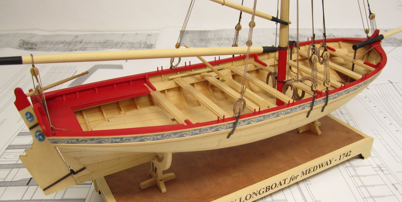
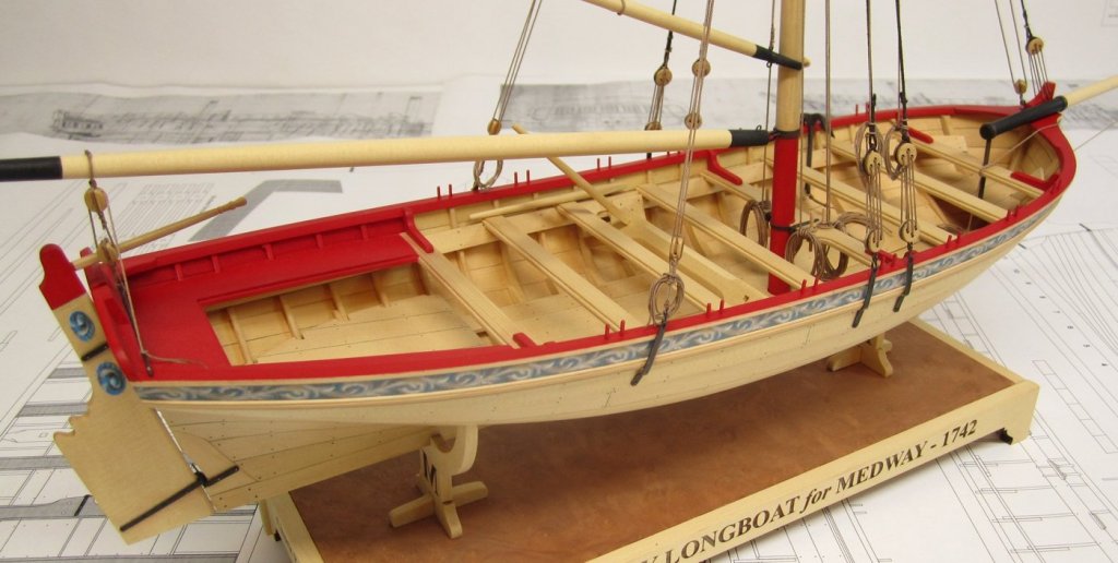
Chucks Medway Longboat
Images added to a gallery album owned by Chuck in Medway Long Boat - 1742 - Public group project.'s Medway Gallery
-
-
ropecolor1.jpg
Chuck posted a gallery image in Medway Long Boat - 1742 - Public group project.'s Medway Gallery
From the album: Chucks Medway Longboat
© Chuck Passaro
-
riggingdone6.jpg
Chuck posted a gallery image in Medway Long Boat - 1742 - Public group project.'s Medway Gallery
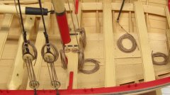
From the album: Chucks Medway Longboat
© Chuck Passaro
-
riggingdone5.jpg
Chuck posted a gallery image in Medway Long Boat - 1742 - Public group project.'s Medway Gallery
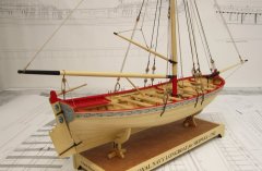
From the album: Chucks Medway Longboat
© Chuck Passaro
-
riggingdone4.jpg
Chuck posted a gallery image in Medway Long Boat - 1742 - Public group project.'s Medway Gallery
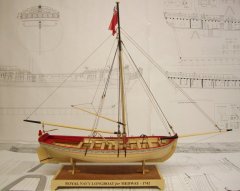
From the album: Chucks Medway Longboat
© Chuck Passaro
-
riggingdone2.jpg
Chuck posted a gallery image in Medway Long Boat - 1742 - Public group project.'s Medway Gallery
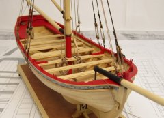
From the album: Chucks Medway Longboat
© Chuck Passaro
-
riggingdone1.jpg
Chuck posted a gallery image in Medway Long Boat - 1742 - Public group project.'s Medway Gallery
From the album: Chucks Medway Longboat
© Chuck Passaro
-
riggingdone.jpg
Chuck posted a gallery image in Medway Long Boat - 1742 - Public group project.'s Medway Gallery

From the album: Chucks Medway Longboat
© Chuck Passaro
-
hullkitparts.jpg
Chuck posted a gallery image in Medway Long Boat - 1742 - Public group project.'s Medway Gallery
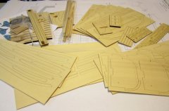
From the album: Chucks Medway Longboat
© Chuck Passaro
-
NOT TRUE AT ALL......This kit is not anywhere on the Master Korabel website. MK does NOT make a kit of this model.
-
Falkonet is not Master Korabel.... They are two very distinctly different companies. There is currently a dispute about Falkonet which has NOT been 100% verified. However no it is not current;y a banned MFG. AND I repeat.......Falkonet is a very different company than Master Korabel. Chuck
-
Well...so the bottom line is that this isnt true at all except for the old companies that havent tried to innovate. Newer smaller companies have the advantage in many cases....as can be seen with the demise of AL, Euromodel, Mamoli and probably some of the others.......Caldercraft???? Maybe too if they dont start doing anything new. Although we have dozens and dozens of their kits being built as build logs. They are still quite popular.
-
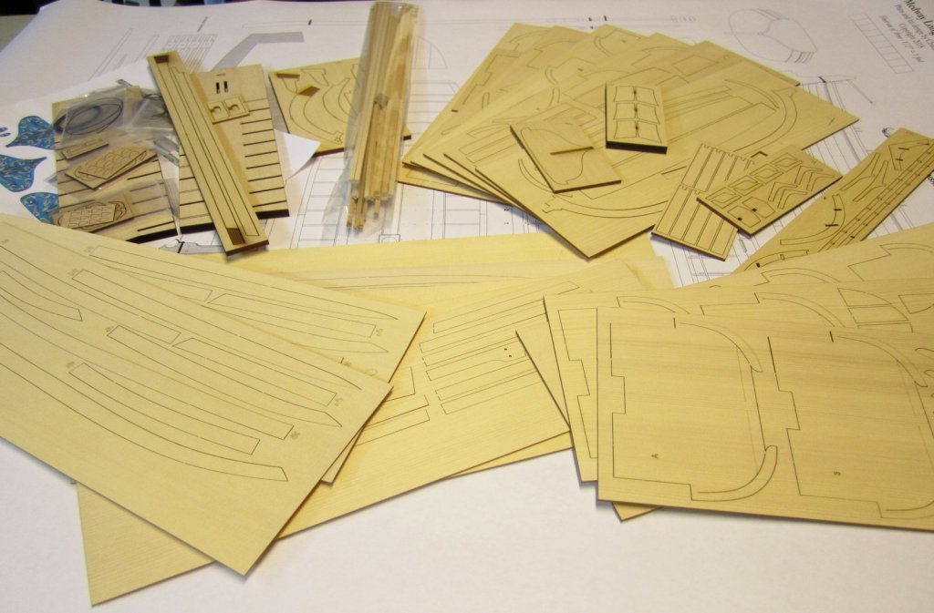
You also need to understand that those kits made 25-30 years ago would never be good sellers now. They are just a handful of laser cut parts made from sub par wood. .... Along with a bunch of wood strips and some bad castings. Model builders expect a lot more today for their money and they are notoriously frugal. To give a builder what they expect these days is quite expensive. It would be very easy and affordable for me to design a new kit like Model Shipways Armed Virginia Sloop. There are about five laser cut sheets in the entire kit and the instructions are 30 pages long. It would never sell!!!! They were basically starter kits with a bunch of raw wood. In contrast.....my new kit of the longboat has 26 laser cut pieces and almost no strip wood.....very expensive, with about 100 pages of instruction. The old kits can now be considered semi scratch in my opinion....especially if you ditch the castings. Very few parts were laser cut and designed with ease of construction in mind. And all this for a smallish kit of a longboat. Folks dont even want to learn to plank anymore. They want even larger kits to have all of the planking pre-spiled and laser cut......but they only want to spend $250. Very very different these days to design a kit that will be well-received....Builders have gotten very spoiled. This leaves very little profit per kit when most builders expect to pay about the same as they did for the AVS with cheap wood. Design and prototyping takes a whole lot longer now. At least for anything innovative. So when you consider that any new kit will cost an old established company around $30,000 to develop. This is significantly cheaper for newer small companies where the owners are usually also the designers and also work the assembly lines. I dont have to pay a good designer $50 an hour for about a year and half to design and prototype. I do it myself and it doesnt cost anything. So the old companies cant afford to spend that much to develop a new innovative kit project. They are kind of withering away because of that.
- 22 replies
-
- 17
-
-
Your cedar has arrived in Norway....Probably get it today or on Monday. Ten days https://tools.usps.com/go/TrackConfirmAction?tLabels=la095465259us Chuck
-
Thank You....You can always buy the starter package when it becomes available. That will contain plans minus the templates for the bulkheads. You wouldnt need them because you get them laser cut. Chuck
- 1,784 replies
-
- 4
-
-
- winchelsea
- Syren Ship Model Company
- (and 1 more)
-
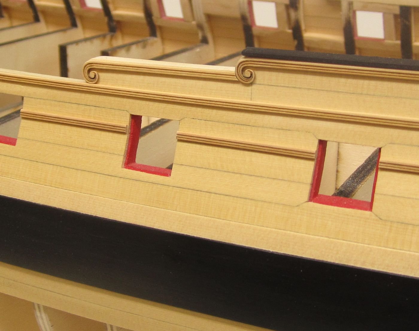
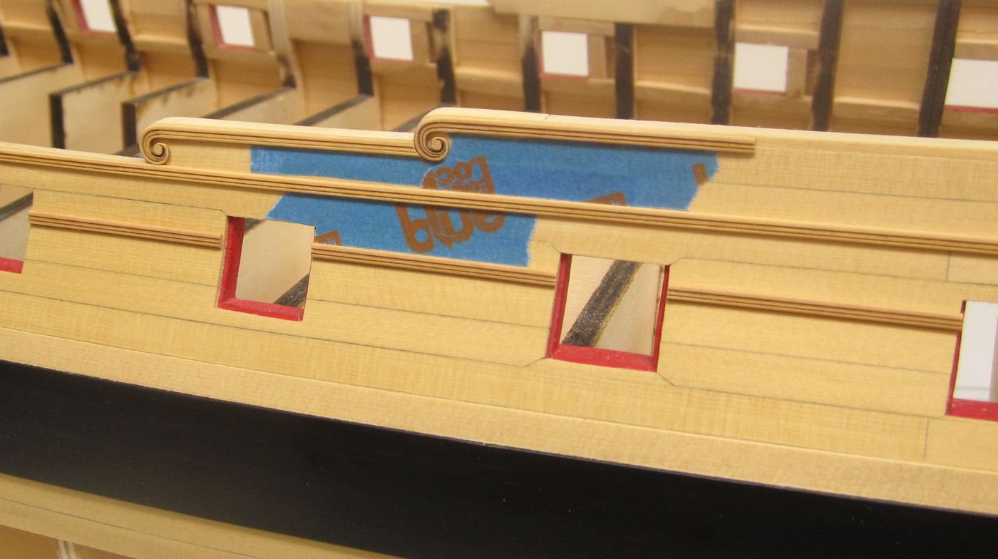
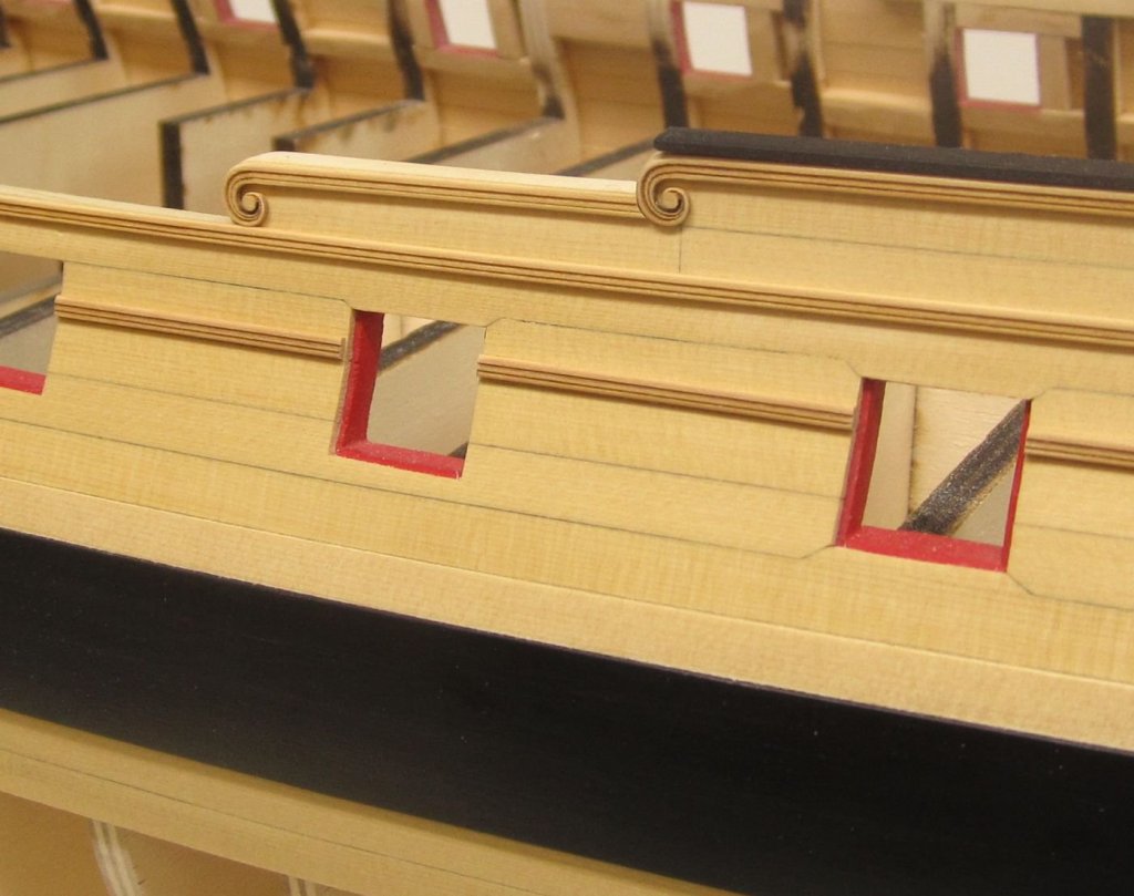
Thanks guys....Chisels are something I am very comfortable with. But when you are trying to mass produce a project for many, there is a whole other side of the fun you guys dont get to see. For examle, in order to try and make a part that is mass-produce-able, there is so much testing and re-testing. I must have laser cut over 100 hance pieces and molding samples. I sanded and finished tested about two dozen of those. When testing, they must be placed on the model temporarily which can be problematic if I am not careful. The first photos I posted yesterday of the molding and hance pieces was probably 50 versions ago. You should compare the photos because it is interesting to see how the design changed over the last few days. With each new try it gets a little batter.....baby steps. This was my final test just about one hour ago with the last iteration of hance pieces and molding. They were lightly tacked to the model with the tiniest drop of glue. But the molding can be hard to see against the same color background. So with each test, I used some blue painters tape where the painted frieze will eventually go. Although not exactly the right color it is close enough to give me a good sense of how the molding will look. Making laser cut moldings and hance pieces is new territory for me. Although I tried it with the Confederacy kit, I wasnt able to test it as much as I can now that the laser cutter is only 3 feet away from my workbench. Many wonder why these kits are so expensive...I cant tell you how expensive it is to test this much while trying to produce the very best product or design concept. This is why it is so upsetting when another company in a foreign land will just wait it out and copy the final product. That saves so much time and money and aggravation. But I digress.....Testing on the molding and hances have lasted three days.....I am so far behind with making blocks and rope!!! These will be the final iteration of hances although the molding between the ports is traditionally different. I just havent had time to develop those yet. Lots more to do. I hope you are interested in the trials and tribulations of a model designer. There are good days and there are bad days. Days where everything you try just turn out like crap....and its back to the drawing board!!! Hopefully that isnt the case here. 🤞

- 1,784 replies
-
- 38
-
-
- winchelsea
- Syren Ship Model Company
- (and 1 more)
-
Dont really know yet. I will probably gang up several parts of the project and over them along with others that will be built in a given Chapter.
- 1,784 replies
-
- 4
-
-
- winchelsea
- Syren Ship Model Company
- (and 1 more)
-
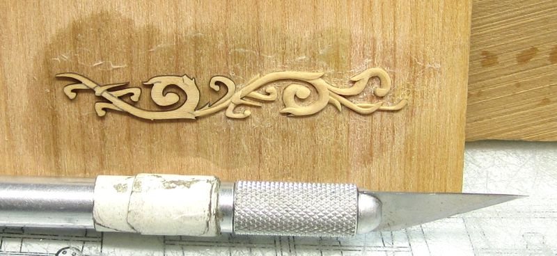
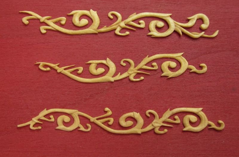
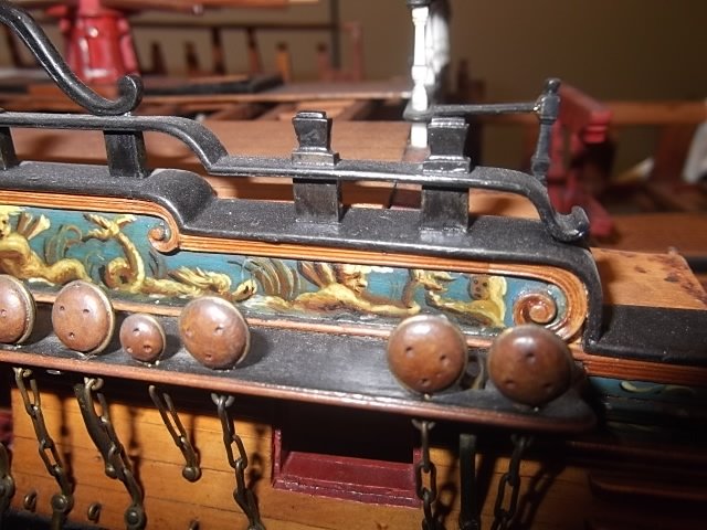
Carved scrolls on actual contemporary model.....I would encourage as many willing to try and carve them but I think my laser cut versions will do just fine. But nothing beats a hand carved version.
- 1,784 replies
-
- 17
-
-
- winchelsea
- Syren Ship Model Company
- (and 1 more)
-
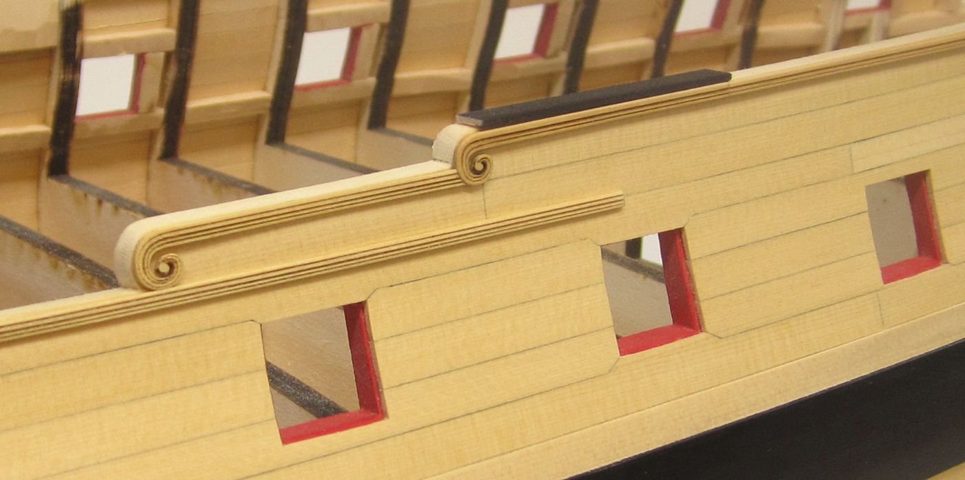
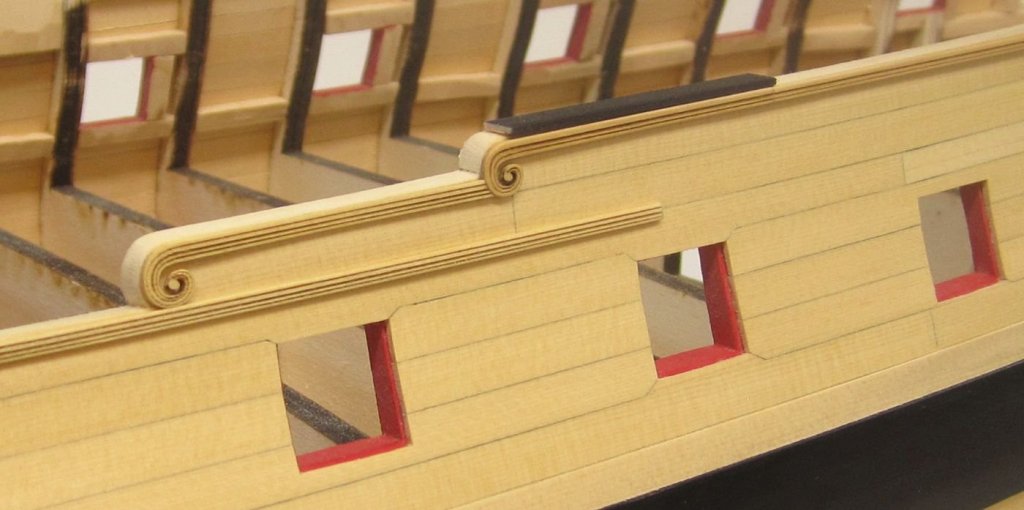
Thank you.....yes I could break out the chisels and blades but the fun challenge for me is to try and engineer a really good part so that I wont have to. While it was fresh in my brain and different ideas were swirling around in there, I decided to do a simplification test with fewer etched grooves. I think this is the winner at it achieves exactly what I am shooting for. The aft upper hance is new and made from boxwood. I will go with boxwood on the final versions too. I also reduced the scroll in size and it is now perfectly sized for the Winnie. I added a simulated cap rail which will be painted black so I could see the molding better. Now back to making rope and blocks which I have fallen very behind with since I spent a couple of days fiddling with the scroll-work and molding.
- 1,784 replies
-
- 35
-
-

-
- winchelsea
- Syren Ship Model Company
- (and 1 more)