-
Posts
9,663 -
Joined
-
Last visited
Content Type
Profiles
Forums
Gallery
Events
Everything posted by Chuck
-
My head hurts just reading through that stuff. I am probably just going to stick with sanding sealer or wipe on poly!!! 😁
- 1,784 replies
-
- winchelsea
- Syren Ship Model Company
-
(and 1 more)
Tagged with:
-
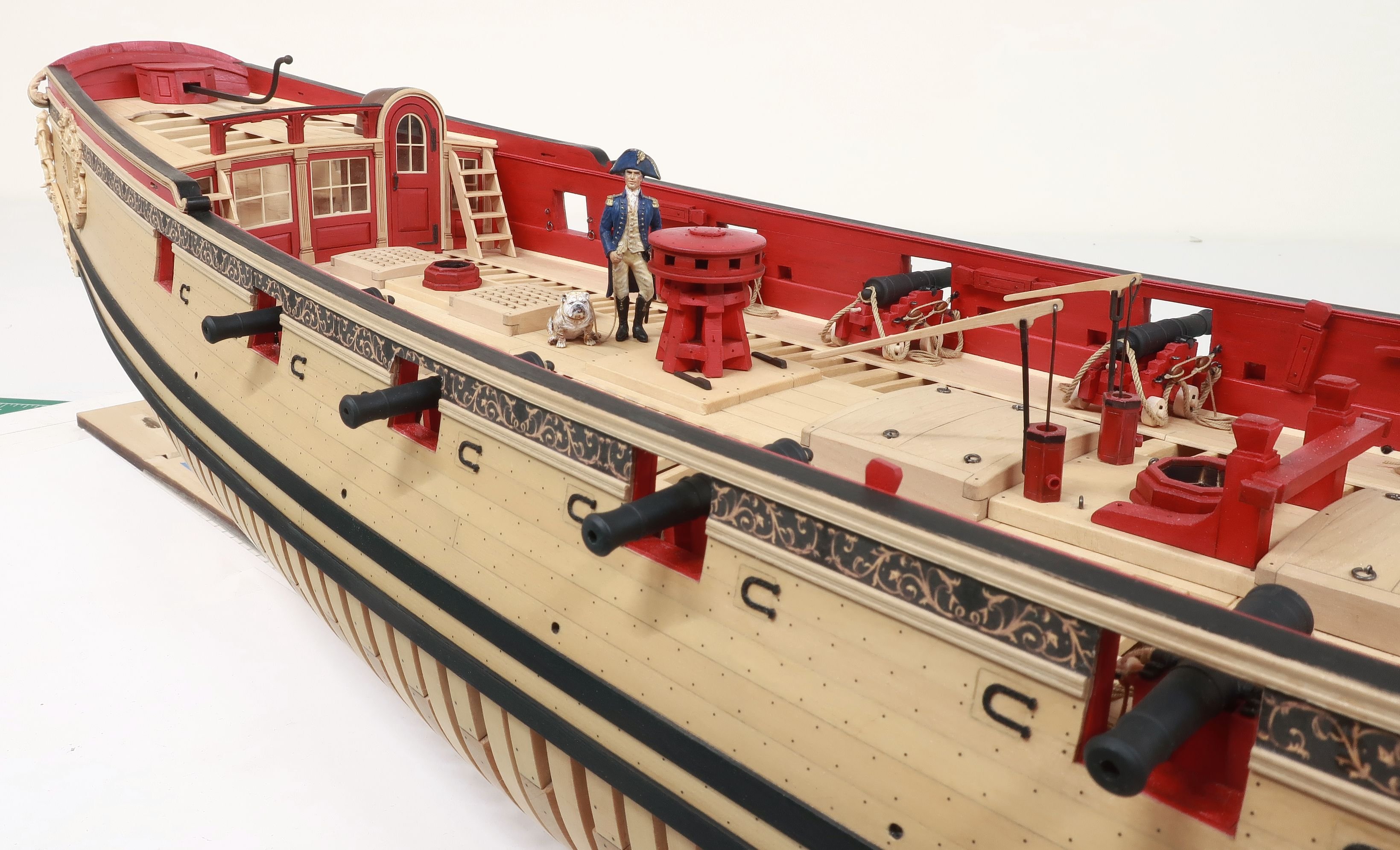
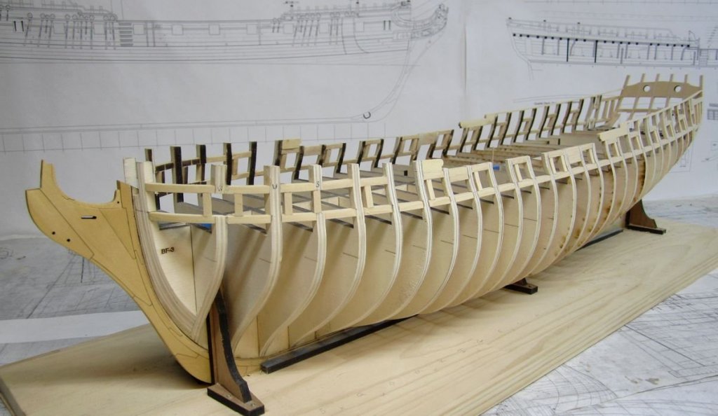
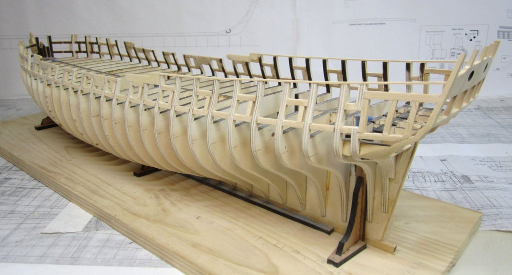
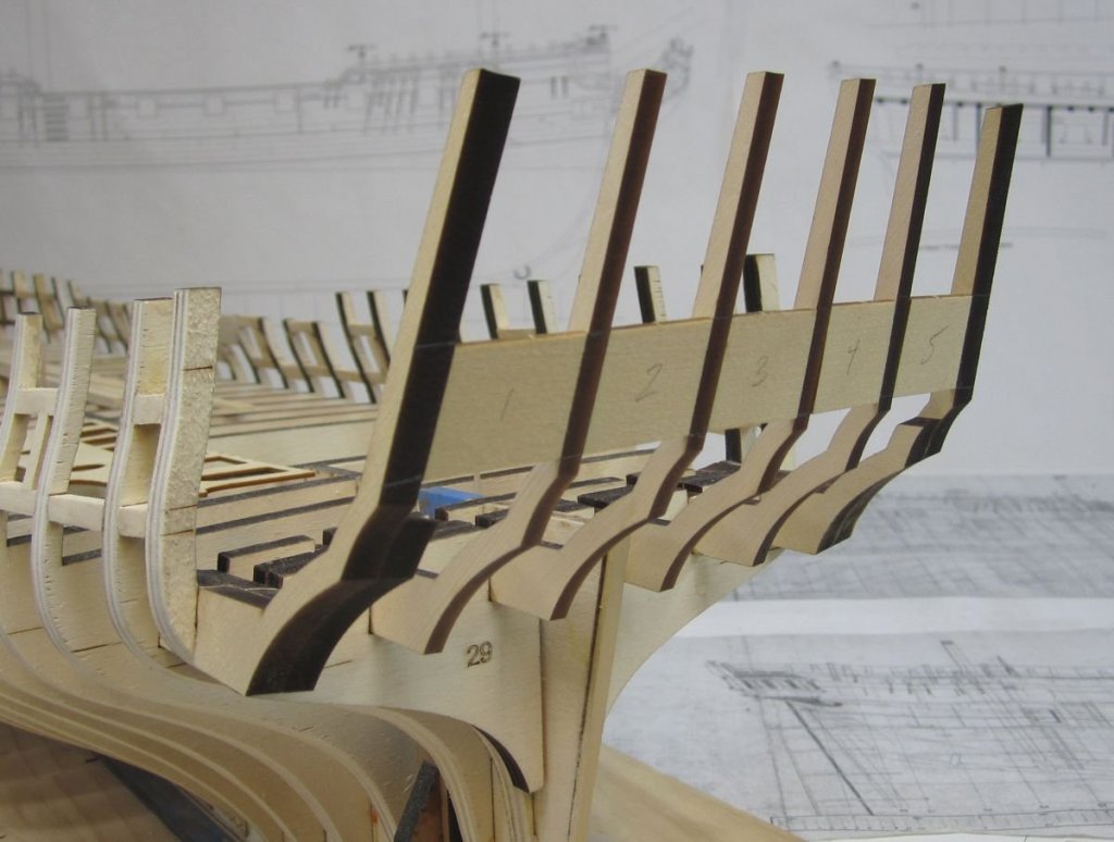
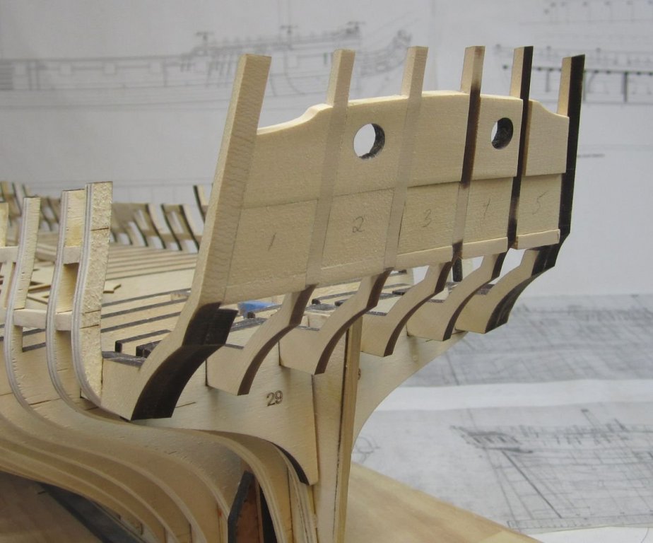
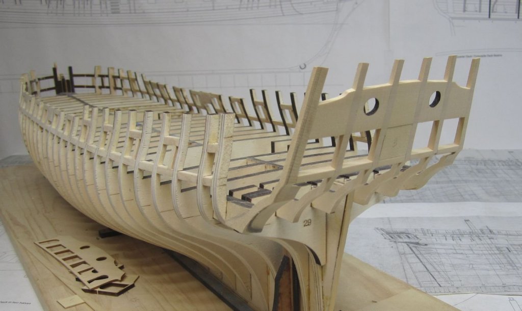
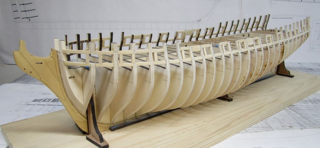
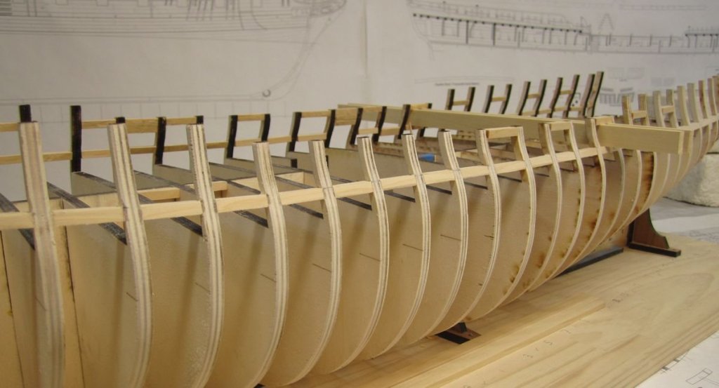
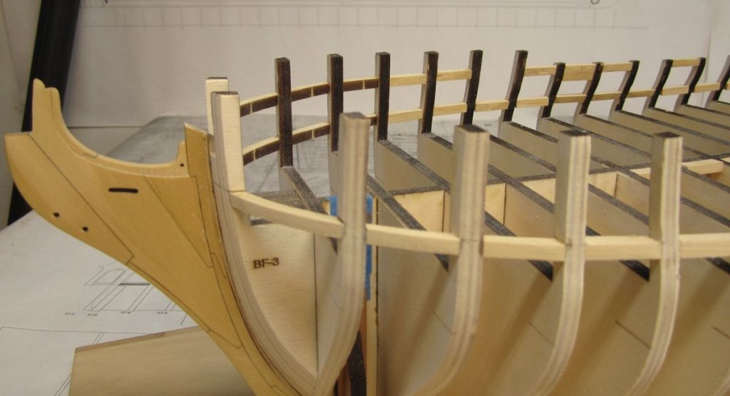
Thank you guys. I finished the quarter gallery framing....I will skip the details on this here. I also added the laser cut hance pieces. Except for the bollard timbers at the bow, all of the framing is completed. The bollard timbers are tricky so I will wait until I get back from the joint clubs show next week to make those. Once they are done it will be time to start planking. Here is what the framing looks like completed....basically this represents all the parts for the starter package including the bollards that I will make next week. Chuck
- 1,784 replies
-
- winchelsea
- Syren Ship Model Company
-
(and 1 more)
Tagged with:
-
Really looking good!!!
- 103 replies
-
- queen anne barge
- Syren Ship Model Company
-
(and 1 more)
Tagged with:
-
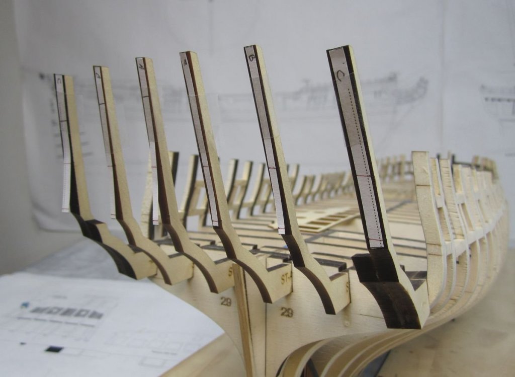
Thanks Rusty, You might be getting a care package in the mail of sorts for this project very soon. Greg, I would love try a varnish but never did it before. I would need to experiment. I dont even know what a good brand would be for that to start with...but I will see. Work is progressing quickly now. The stern frames were added after I placed the last "bulkhead 29" piece in position. They were glued into the many slots for them which should position them close to the angles we need....but not perfectly. Then I taped some tick strips to the frames using a stern framing guide I developed for the project. They were taped to each frame as shown to locate where the stern lights (windows) would be located. The locations for the top and bottom of the windows was transferred to each frame. I then inserted some stern window guides laser cut to shape between each frame. These are the exact shape and size for the windows. I didnt glue them in at all. They are just pushed between each frame and they stay in position really well. We will be removing them after the sills and framing for the windows is completed. It doesnt matter if you add the top or the bottom framing (sills) first. They were all laser cut but still require some beveling on the sides to conform to the curved shape of the stern. I just used a 3/16 x 1/4" strip to make the lower sills. Its tricky getting the angles correct so I had a few do-overs. But this is a crucial part of the build so I was very careful to get a good fit. They were thicker than what was needed so I could fair them once they were glued in position. The window templates were a godsend!!! If my sills were too wide they spread the frames apart and the template fell out. This is a good indication that you still need to sand them a bit more for a perfect fit. Only when after positioning the sills and they didnt make the window templates fall out did I glue them in permanently. Then I started fairing the fore and aft sides to thin down the transom framing to about 3/32" thick along the top edge of the upper sill pieces. This is the time to do the inboard side because you have good access to it before the quarter gallery framing is added. This is what it looks like after the fairing was completed....I still have to fair the port and starboard sides and bulkhead 29 to conform to the shape of the hull....I will do that later today or tomorrow. Then its time to do the quarter gallery framing.... So close to finishing the skeleton framing now!!!! I left the center window guide in position to show you guys how well they worked. This was a much easier way to align and frame the stern than the previous methods I have used.
- 1,784 replies
-
- winchelsea
- Syren Ship Model Company
-
(and 1 more)
Tagged with:
-

Queen Anne Barge by Beckmann - 1/24
Chuck replied to Beckmann's topic in - Kit build logs for subjects built from 1501 - 1750
I have no idea...could be a few things. My guess is the frames were not securely glued into the keel allowing for some movement. Or the base was warped from the beginning and and just not noticeable. There isnt much you can do about it at this point though. I am sure nobody will notice. Impossible to tell in the photos. Chuck -

Queen Anne Barge by Beckmann - 1/24
Chuck replied to Beckmann's topic in - Kit build logs for subjects built from 1501 - 1750
Really fine work. The guilded carvings look fantastic. -
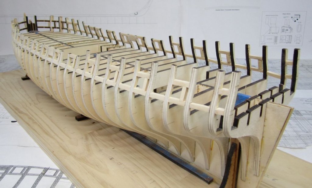
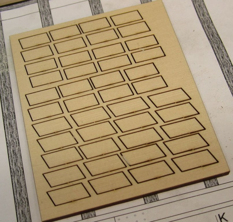
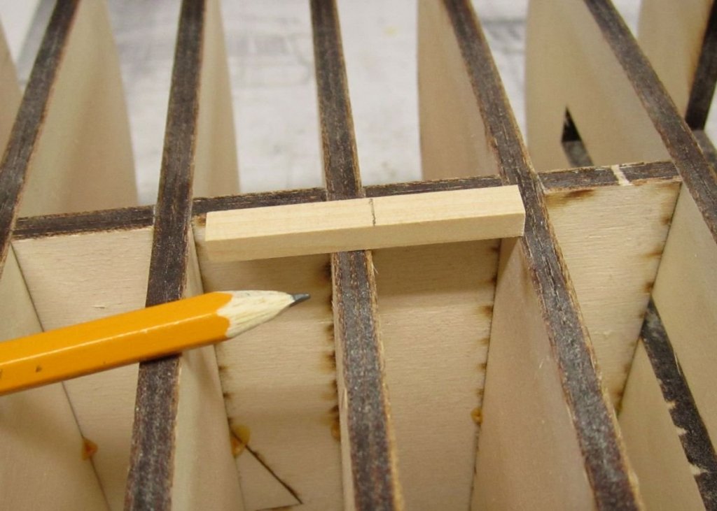
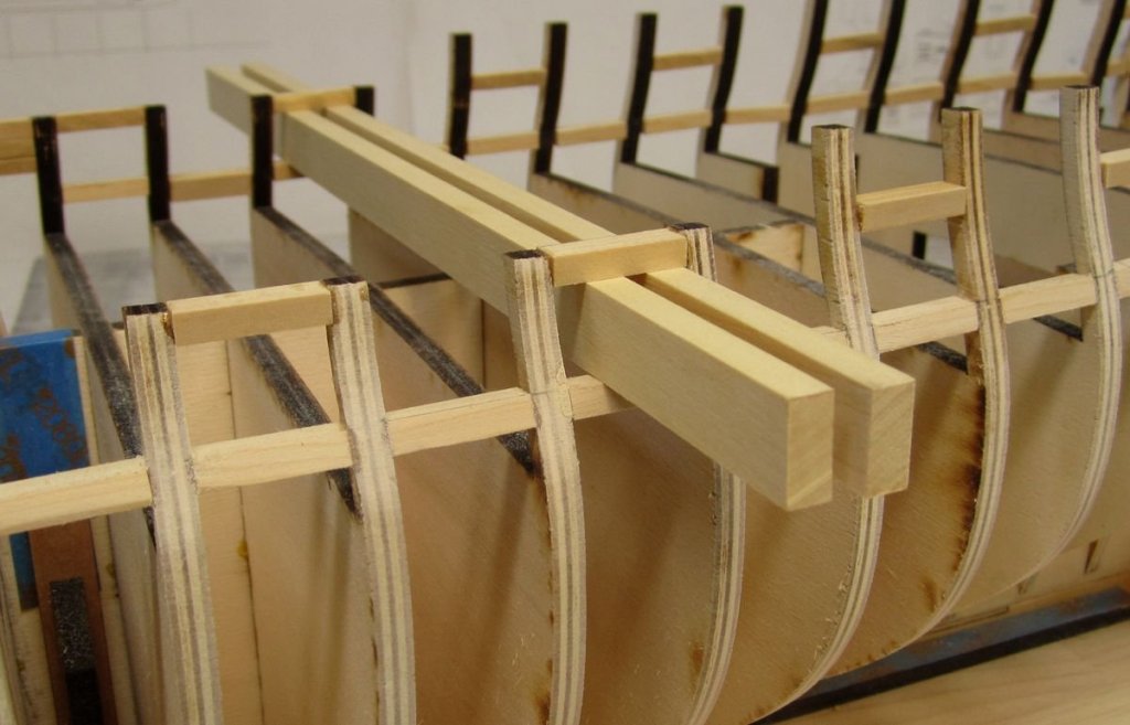
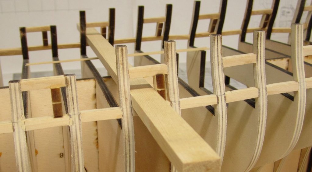
I have been making some steady progress on the framing. I just didnt want to bore you guys with this part of the project. Building the skeleton and framing is not that fun to look at. But here is the quick run down.... The bottom port sills were added first. Even though you really only need them where the gun ports are, I recommend that the bottom sills are placed between every bulkhead. It really makes everything solid. If you cut the sill to the correct length it also squares up teh bulkheads really good. Even the best attempts at squaring them to the false keel doesnt work. You might note that the three sections at the bow for the sills are laser cut. That makes it much easier. You may be tempted to measure the length off your model where the port sill is going to placed. This is the worst thing you can do. It is too easy to push the bulkhead one way or the other which of course forces the other side of the bulkhead in the opposite direction. This will really screw up your gun port placement. You could also measure off the plans....this is better but still not ideal. The best place to check the length between two bulkheads is on your model BUT....up against the false keel. This will give you the best results. If you do this for both sides everything will be really square and symmetrical. See below. Once done this was repeated for the upper sills or lintels. I used a spacer the correct height to place them all easily without measuring. I only did these where the actual ports were and a few other important locations. These are all shown on the plans. Then the port sides are added.....I have laser cut these. There are many shapes and angles to choose from. You still have to bevel the top and bottom where needed because they must be perfectly vertical.....just like the bulkheads. I used a spacer for these too so the ports were all the same width. This is what it looks like with all the port framing finished. Pretty boring stuff. I am about to start on the stern framing. I should be planking before very long. The outside was faired smooth. I wont bother with fairing the inboard side of the bulwarks yet. Its better to wait until after the hull is planked above the wales for that. Although I will probably rough chisel some heavy stuff away a little at time inboard when the mood strikes me.
- 1,784 replies
-
- winchelsea
- Syren Ship Model Company
-
(and 1 more)
Tagged with:
-
Looking real good so far. Well done. Happy you joined the group.
- 87 replies
-
- medway longboat
- Syren Ship Model Company
-
(and 1 more)
Tagged with:
-
Malco saw has some great stuff. I have used them before. And i have used Thurston but honesyly, over the last year or so I have been very unhappy with tThurston blades. The last two orders i got from thurston forced me to leave and try Malco. The Thurston blades were so dull I figured they were used and not resharpened properly. In contrast, the blades from Malco were razor sharp and cut even boxwood like butter. I am a convert and very very happy with Malco blades. Wish I had switched years ago.
-
Soak the parts in 90% rubbing alcohol until the glue softens. It will take a while.
- 10 replies
-
- 18th century longboat
- model shipways
-
(and 1 more)
Tagged with:
-
Even though you can probably get there about 90 percent with CAD, Each plank still needs adjusting and tweaking for a really good fit. At least with me, i like to adjust each plank for real life issues the computer would never pick up like the kerf of the laser cutter or adding a little extra width to compensate for creep and bevel. In fact, all of my pre spiled planks for the longboat were done without a computer at all. I used the method described in my build log for it. They were spiled the old fashioned way. Then it was scanned and traced into a vector program. Then i tweaked each one as described above.
-
No bowsprit ring would have been used at the stem. This was only used when the bowsprit was NOT well contained under the cap rail. Because the bowsprit is very secure between the frames and cap rail no ring would have been needed. I had it originally but removed it after this info came to light. Looks good!!!
- 574 replies
-
- cheerful
- Syren Ship Model Company
-
(and 1 more)
Tagged with:
-
Indeed.....everyone needs to set up an album for their photos. One album per subject and only include photos of completed models. No under construction pics as they should be posted in build logs. A description of the project is also important.....what kit...MFG or if scratch, based on what plans and built with what types of materials etc. Chuck
-
Beautiful work Ben. I wouldnt have expected anything less!!! Really looks good with exposed frames.
- 64 replies
-
- medway longboat
- Syren Ship Model Company
-
(and 1 more)
Tagged with:
-
Boy she does look pretty. You did an absolutely masterful job on the Cheerful project. I do hope you enjoyed building it!!! One of the best Cheerfuls I have seen and I have seen a whole lot of them.
- 51 replies
-
- cheerful
- Syren Ship Model Company
-
(and 1 more)
Tagged with:
-

Queen Anne Barge by Beckmann - 1/24
Chuck replied to Beckmann's topic in - Kit build logs for subjects built from 1501 - 1750
Yes that stuff...but the matte finish. -

Queen Anne Barge by Beckmann - 1/24
Chuck replied to Beckmann's topic in - Kit build logs for subjects built from 1501 - 1750
One thing you might want to try is a spray fixative. I will spray the entire model with a light spray of matte fixative or dull coat. This really evens out the red paint. You should give it a try on those extra pieces. I spray from about 18 inches away from the model and it really does wonders for the finish. -
No not yet. I havent had time to make the new rope yet. I am still using the cotton/linen stuff. I am hoping to have more rigging kits in about a week. I am stuck working on a few things on the house now. I have to knock off a few on the honey-do list or I will be out on the curb. If you know what I mean....😂
About us
Modelshipworld - Advancing Ship Modeling through Research
SSL Secured
Your security is important for us so this Website is SSL-Secured
NRG Mailing Address
Nautical Research Guild
237 South Lincoln Street
Westmont IL, 60559-1917
Model Ship World ® and the MSW logo are Registered Trademarks, and belong to the Nautical Research Guild (United States Patent and Trademark Office: No. 6,929,264 & No. 6,929,274, registered Dec. 20, 2022)
Helpful Links
About the NRG
If you enjoy building ship models that are historically accurate as well as beautiful, then The Nautical Research Guild (NRG) is just right for you.
The Guild is a non-profit educational organization whose mission is to “Advance Ship Modeling Through Research”. We provide support to our members in their efforts to raise the quality of their model ships.
The Nautical Research Guild has published our world-renowned quarterly magazine, The Nautical Research Journal, since 1955. The pages of the Journal are full of articles by accomplished ship modelers who show you how they create those exquisite details on their models, and by maritime historians who show you the correct details to build. The Journal is available in both print and digital editions. Go to the NRG web site (www.thenrg.org) to download a complimentary digital copy of the Journal. The NRG also publishes plan sets, books and compilations of back issues of the Journal and the former Ships in Scale and Model Ship Builder magazines.

