Chuck
-
Posts
9,703 -
Joined
-
Last visited
Content Type
Profiles
Forums
Gallery
Events
Everything posted by Chuck
-
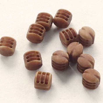
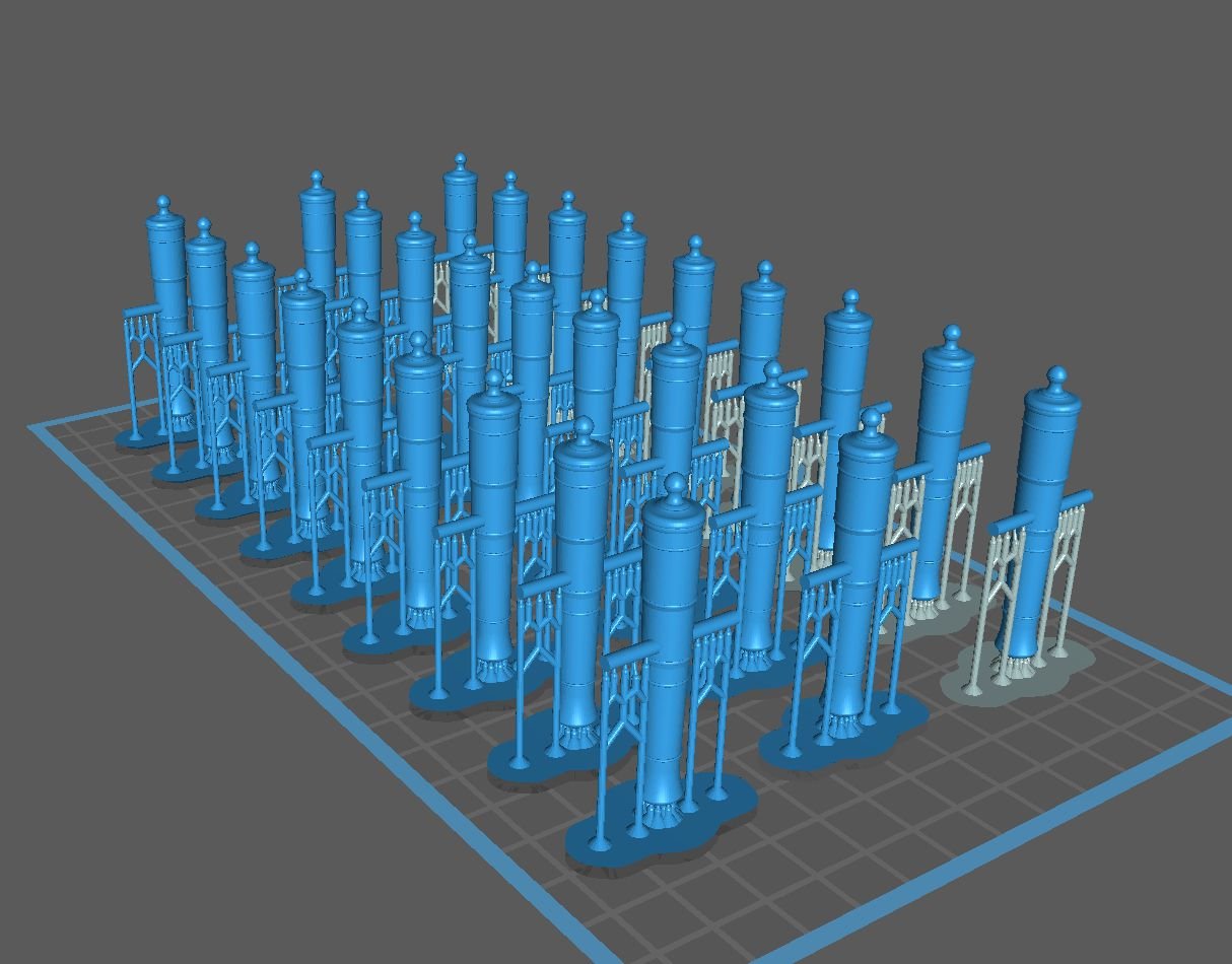
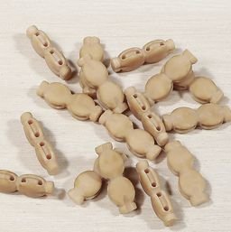
 This week I will be starting to make the darker "Swiss Pear" colored rigging blocks. If this is your preference then watch my store for the next few days as they start to appear. Same low low price as the natural "boxwood" and yes half the price of other after market blocks that quite frankly are not as good in my opinion. These are 5/32" singles and doubles. First batch of these off the printer. Chuck
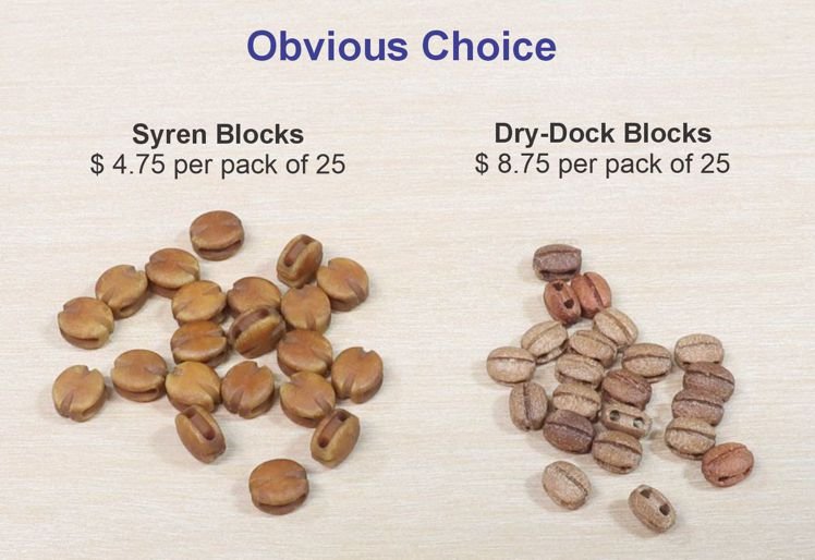

-
Yes i do but my supplier is in poland. The owner has switched his factory over to make munitions for Ukraine. So until he switches back it will only be 3d printed. Chuck
-
Its an old picture that I used and yes I am currently using that for my base shape on these now. Its a lot easier. Live and learn. Thanks.
-
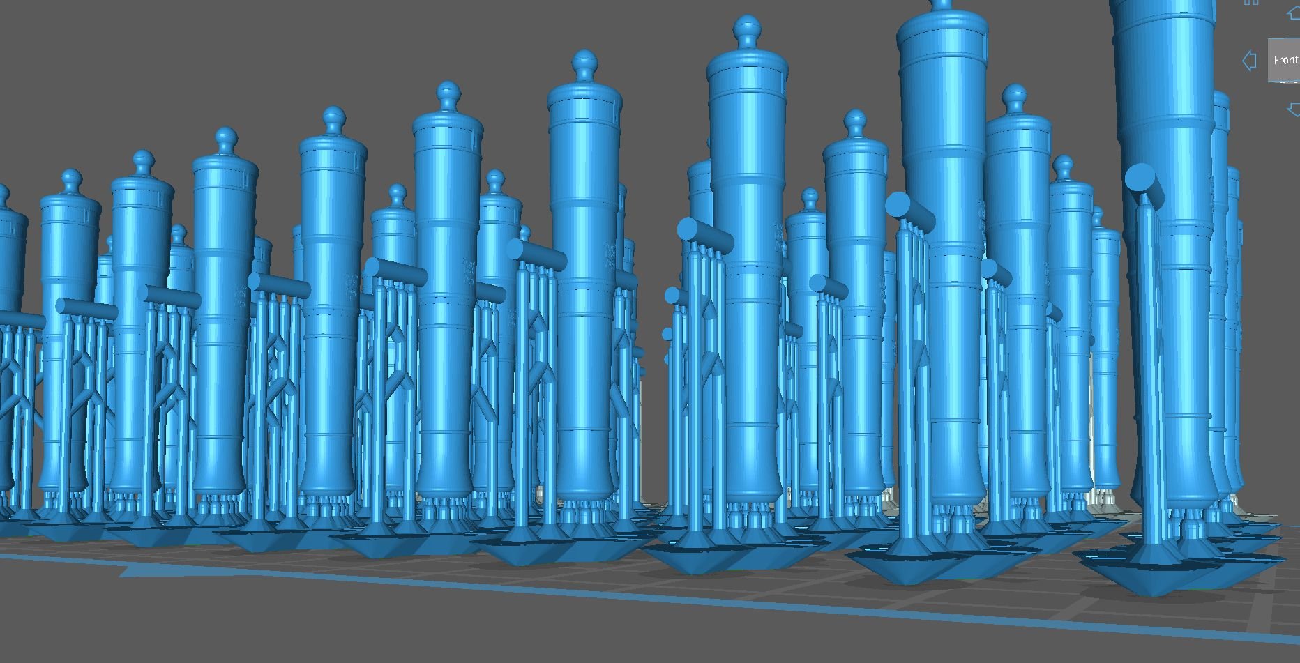
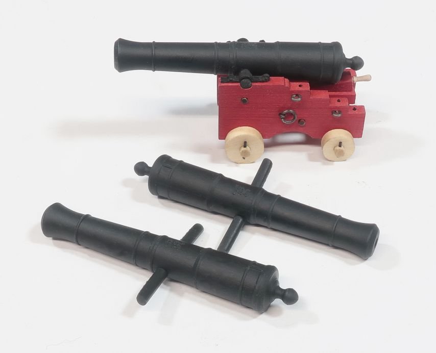
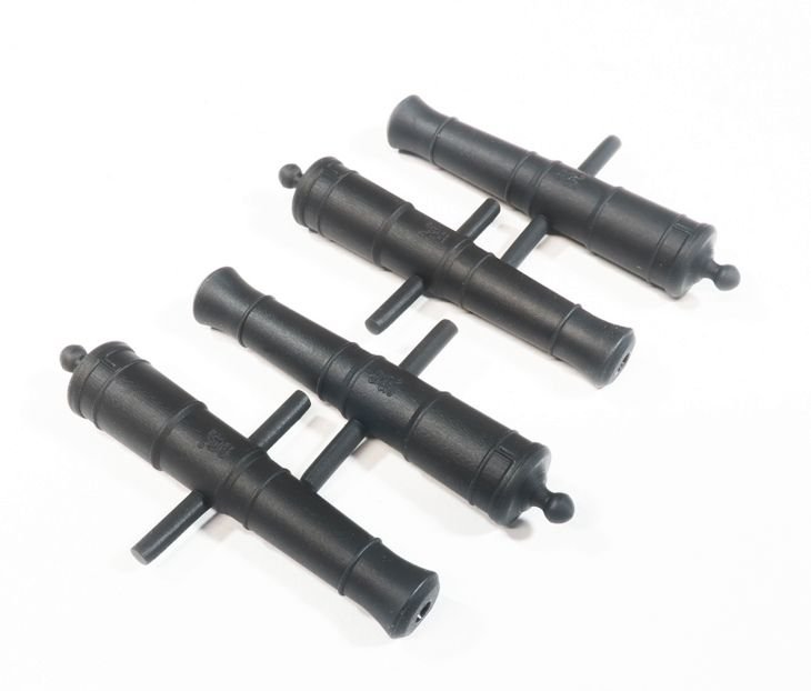
Thank you Ron. I am now updating the guns on my Speedwell Carriages. These are the new 3D printed cannon from the file you created. They look fantastic. The surface quality is better than I could have ever expected. If you have a 3D printer it is well worth the 5 hours to print these. I have an Elegoo Saturn Ultra printer 12K. You guys should take advantage of Ron's hard work and generosity here.
-
That looks so good. I hope you had fun with it. Chapter three is just around the corner. chuck
-
To start the sizes I already offer in my store. But then I will make some additional.
-
That looks wonderful. Really nice job on that.
-
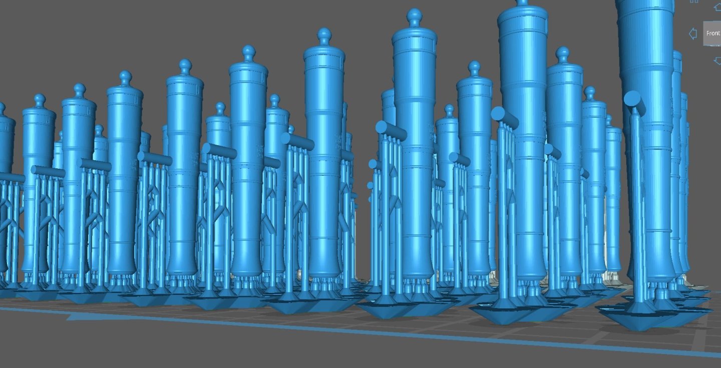
Here is a test print run of an Armstrong Fredrick which Ron (thibaultron) sent me. Its a lovely cannon and prints very nicely. Ron has posted the stl files for these for everyone to print in our 3D printing forum area. I am very thankful to Ron. I will be selling these in my shop with his permission to anyone who does not wish to go down the 3d printing rabbit hole. These are printed in Gray/black resin. They are hard to photograph but hopefully you can see the royal monogram on the barrels and vent hole. The trunnion pin is also extra long so it will fit any carriage. Just snip off the excess and sand it flat. I know you guys sometime buy barrels to fit the carriages supplied by the kits you are building. Just in case.
-
Really nice. Cant wait to see it in Person Mike.
-
That looks wonderful…super clean.
-
Wow...really busy for sure. Everything looks great. I cant wait to see it all assembled on the model. Chuck
-
I hope to have them in the future. Ron has sent me an Armstron Fredrick cannon stl he made and I will be printing those very soon. I am very grateful for that. Once those are done maybe another type of cannon or yes even a carronade. And if Ron has other files I would be thrilled to print those too should he want to pass them along. But all this does take time. Slowly but surely. I also have ships wheels ready to go and some other things. So lots of goodies yet to come. Chuck

-
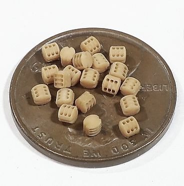
I agree with you. But 2mm blocks like these sell like crazy. I dont get it but then again I model at a larger scale. Smaller will be tough. I may call it a win and stop at 2mm becuse they are a pain to make actually. If one drops off the supports and in the VAT of the printer I have to break down the machine and clean it all. That happens a lot with these tiny pieces because you cant use heavy or many supports. That would ruin the look of the blocks. So I may just say 2mm is small enough but you know me. I may just try it once to see if I can do it. It is truly amazing though. Even with a macro photos you cant see any layer lines or that rough surface you guys are probably familiar with. Even made out of wood and cnc they look kind of rough at this size. But these look pretty pristine if you can rig them.
-
Well wait a few days so I can finish these...LOL.
-
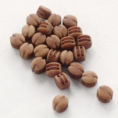
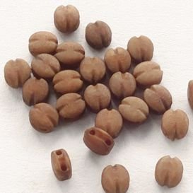
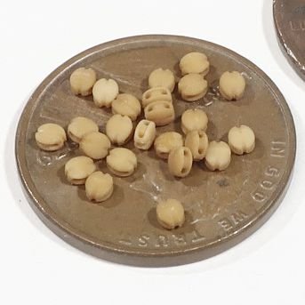
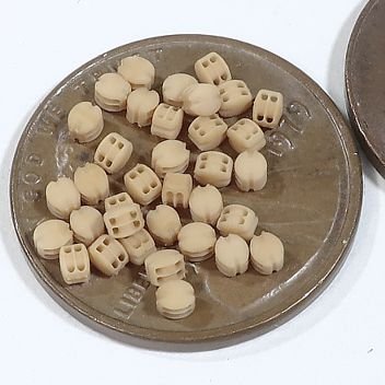
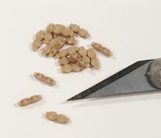
I am all done with the different blocks and am fully stocked. So I am now going back and trying to make the tiny stuff that a lot of folks need. These are tricky and to make make them correctly proportioned and looking real even tougher. Anyway these are true 2mm single blocks. I measured my old wooden 2mm blocks and they were probably 2.2mm long. The stuff from Coastline and Dry-duck are even larger. These should be available really soon. Probably today. Doubles and triples to follow. Now can I make them even smaller? I really dont know. But I am willing to try for those who like to build the small models. Take out a peny and look at how big the date is. That is how small these blocks are. The holes are clear and the details crisp. Now how do you strop and rig them. Thats up to you small scale model builders to figure out. Just use the correct scale rope. Tiny stuff. Fly tie stuff for sure. Chuck
-
Such a nice looking model. You are really doing a fine job. I will be following along.
- 99 replies
-
- 2
-

-
- ancre
- La Mahonesa
- (and 1 more)
-
That would be insane. You dont realize just how small they are. I doubt that would work. Far easier to to use other methods I think. Chuck
-
Absolutely its OK...please start one.
-
Yes but I have no idea when I will find the time.
-
Maybe but if too small it would be impossible to keep the sheave holes clear of resin. So I doubt these could be printed as small as some folks can imagine. So its not possible at really small sizes. chuck
-
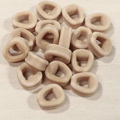
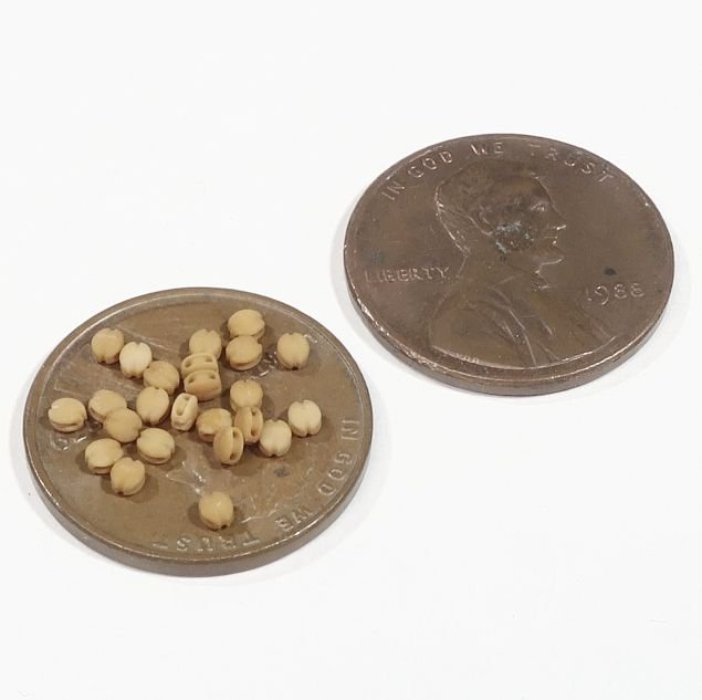
Really small sister blocks...3/32". Now for some open hearts.
-
That looks splendid!!!
-
Eventually yes...but life has a funny way of taking turns. Work will be continuous of course but on what all depends on what is going on. For example...I have the Hudson River sloop to get done first as it will be for a museum on the Hudson River. But Speedwell must be finished first and of course....and turning to 3D printing because making from wood by hand or CNC is too time consuming and expensive these days. Things just seem to come up and change the schedule. Chuck
-
Yes I plan on making guns of all sizes. I just have to get through these blocks first. I am using an Elegoo Saturn 3 Ultra Chuck
-
Closed hearts now in stock. Sister blocks also starting to appear in my store. When I list them as 3/16" sister block it means there are two 3/16" single blocks in this sister block. I will be making all of the usual sizes. Two 3/32" single block sisters etc.