Chuck
-
Posts
9,725 -
Joined
-
Last visited
Content Type
Profiles
Forums
Gallery
Events
Everything posted by Chuck
-
 Looking good ken
 -
Yes up in the woods...lots of space for a shop. I cant wait to get there. Its the worst time to be trying to sell your house but I just dont want to waste anymore time. Chuck
-
Yupp…you know how difficult it is to clean up the shop and put stuff away every hour or so. Then when they leave I take it all back out and try to get started again.
-
Just an FYI. Its been crazy trying to get any work done while the house is up for sale. But I wanted to update everyone on the availability of chapter 3 parts. In-between showings of my house I have been laser cutting chapter 3 parts and have 12 sets ready to go. I am putting the final touches on the instructions as I write this. I just received the three printed plan sheets that will come with this installment as well. I am hoping to having these sets up on my site and in stock by Friday. But with a little bit of luck and fewer house showings I may have them ready on Wednesday. The house has been on the market for 2 weeks now. We have had two offers so far and yes both have fallen through. It seems that being pre-qualified for a mortgage isnt all its cracked up to be. After accepting both offers we soon discovered the buyers were not pre-qualified for the amounts they offered...LOL. So we continue to show the house. Even this close to Thanksgiving we have a ton of traffic and showings. Its driving me crazy as I have to leave the house and stop working while the buyers are inside. So I walk around the block a few times until they are gone. Hopefully the 3rd offer will be the final whenever it comes. I really want to get back to working on the model soon. Chuck
-
Will the Medway Longboat kit ever be made available again?
Chuck replied to alde's topic in Wood ship model kits
Yes but not for a while....sorry. I am doing my best....but its a lot for one person to make all these parts and kits. Chuck -
Beautiful stuff. Nicely done.
-
Really looks beautiful....just wait till you get those headrails on. It will be a show-stopper for sure.
- 399 replies
-
- 2
-

-
- winchelsea
- Syren Ship Model Company
- (and 1 more)
-
Unknown Royal Yacht kit.
Chuck replied to Lucius Molchany's topic in - Kit build logs for subjects built from 1751 - 1800
Its fine as long as it isnt a copied kit. If you have the box send me a picture via pm and i will let you know if its ok. If its not a pirated kit you will be fine…in the meanwhile check the plans for the name of the ship and adjust your build log title. I can also help you with that so it meets our guidelines. -
I usually go with 3/64 thick by 1/16. You could go thinner but I prefer a little more meat. I will at times go wider on larger models but 1/16" wide usually works just fine for me. If you are just ordering a few strips from Joe for this purpose, I would get both 1/32" and 3/64" thick strips which wont costs much considering you will have to pay shipping which will be the same for both thicknesses. I would go with boxwood or yes even cedar but any wood that isnt splintered will work just fine. Boxwood preferred.
-
Looks great Mike.
-
Just look at the materials list in the kit and then send it to Joe. He will give you a price.
-
Looks beautiful indeed. That looks nothing like a kit and really tops off a wonderful looking model. Well worth the effort. It says a lot about taking your time to get the best results.
- 840 replies
-
- 4
-
-
- winchelsea
- Syren Ship Model Company
- (and 1 more)
-
Its looking fantastic Ben
-
That looks fantastic. Really nice detailing.
-
That really looks great. Well done. If you havent built many headrails those certainly look like you made them look easy. Chuck
-
A couple of weeks for chapter 3 parts maybe and they will be about $80 give or take. But remember you will need to buy the wood package from Joe or mill your own planking strips. Chapter 3 is basically planking. chuck
-
As I get ready to laser cut chapter 3 parts I figured I would release the 3 plan sheets that will come with it. These are the last three sheets to complete the hull. There will be more plan sheets for the rigging but this completes the plans for the hull work for folks that dont plan on rigging her. speedwellsheet3.pdf speedwellsheet4.pdf speedwellsheet5.pdf Chuck
-
HM Cutter Cheerful 1806 by Erik W - 1:48 scale
Chuck replied to Erik W's topic in - Build logs for subjects built 1801 - 1850
Yes ….I always add a bit extra. -
HM Cutter Cheerful 1806 by Erik W - 1:48 scale
Chuck replied to Erik W's topic in - Build logs for subjects built 1801 - 1850
You are welcome…any time. -
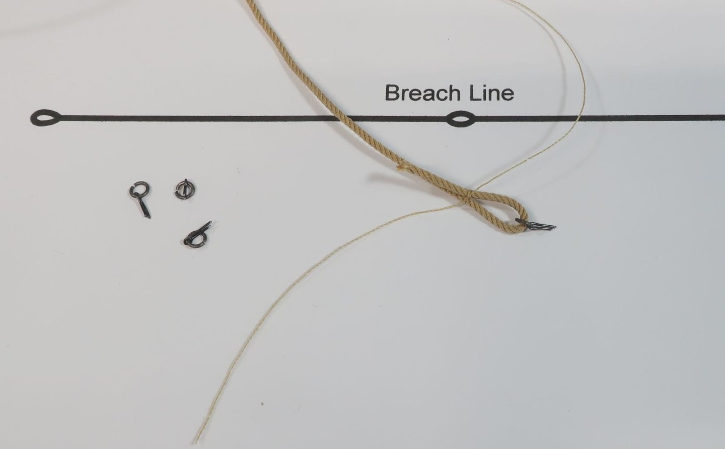
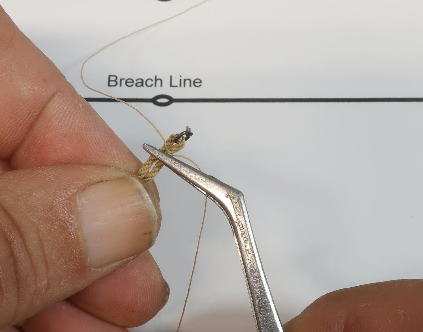
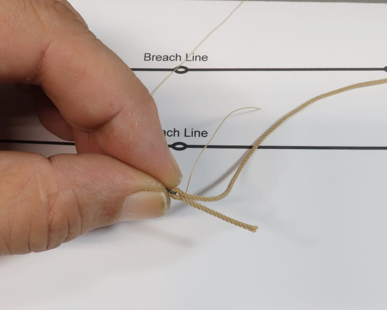
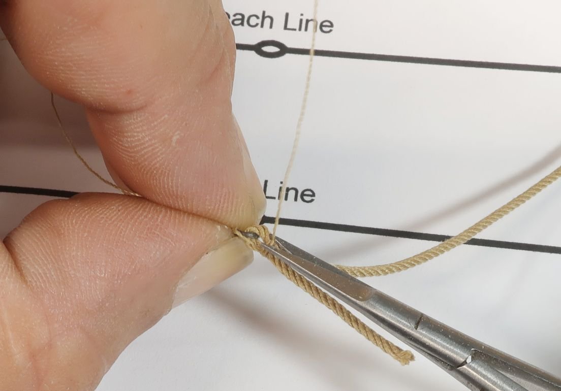
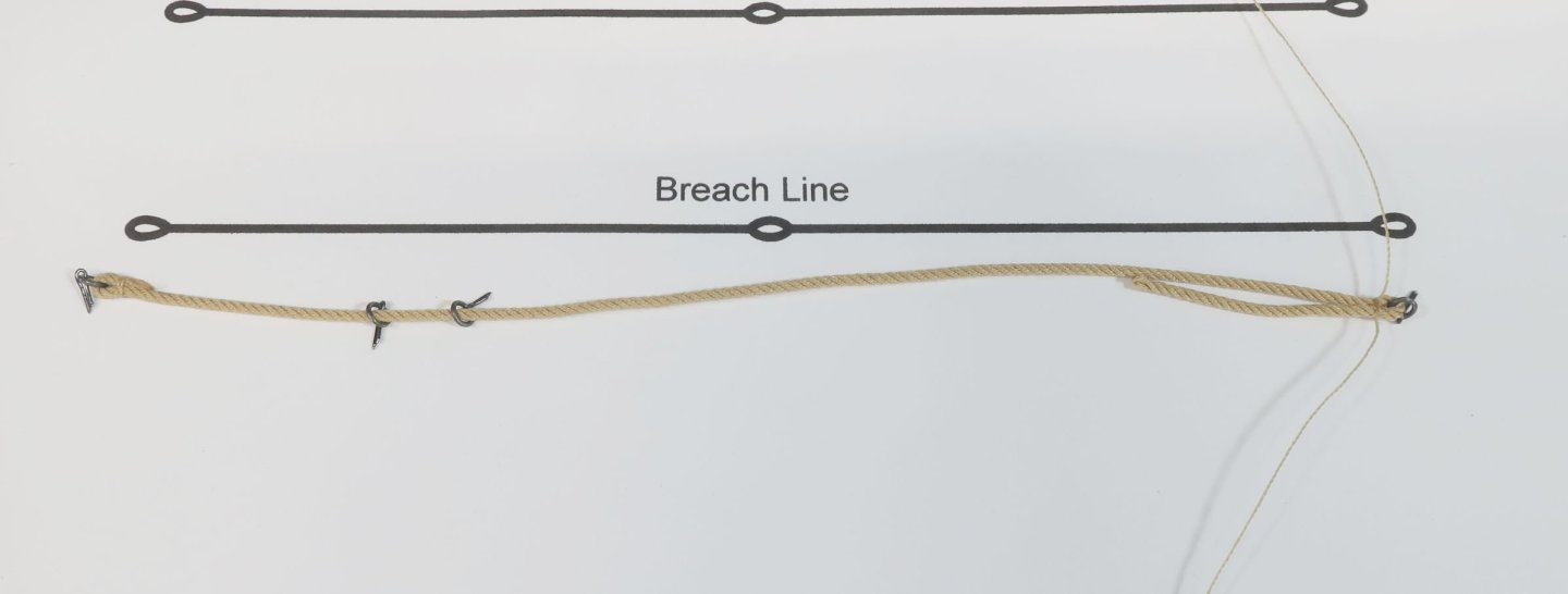
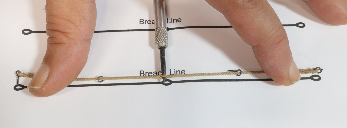
Making the breech ropes. There are many ways to do this. I have simplified it. Here is a step by step. I am using my poly rope so CA glue was used. Start with a breech rope slightly longer than you will need (.055 tan). Have four eyebolts with rings at the ready. Also have whatever line you intend to use for seizing ready. In my case some Guttermann mara 120 thread that matched my rope color. Note that I have made a loose granny knot on this. Or one simple overhand knot but left open and ready to go!!! Place one ringbolt on the rope and simply bend it over to form a loop. Leave the tail a bit longish. I just squeeze the loose loop as shown below with my fingers. No helping hands needed. Then I slip the seizing "open knot" onto the end. Easy peasy. Then cinch it tight.... This is what it looks like. And yes the seizing needs to be pushed closer to the end of the breech and ringbolt. No glue as of yet. Use a tweezers that you are comfy using for this stuff. Slide the seizing which is still just a loose overhand knot closer to the end. It may open a bit. Thats OK. Just tighten it again when the seizing is where you want it. At this stage I place the tiniest bit of CA glue (any glue will work here) on the knot after tightening it. Then I use my fingers to brush away any excess so it doesnt make the rope stained or discolored. Yes you get CA on your fingers. But the rope stays perfectly clean. I see folks moaning that CA darkens and stains the rope. This is nonsense if you wipe most of it away before it dries and you dont use too much to begin with. No discoloration....super simple method and no helping hands or wacky jigs yet. It may be hard to see in the photo below. But I take one loose end of the seizing and pinch it between my fingers and away from the seizing. I am basically pinching the ringbolt and top of the looped breech line. See the other loose end hanging off the far side? Take that loose end and simply wrap it around the breech two or three times. I have seen folks wrap like 25 times and make a long seizing., This never lays correctly and will look sloppy. I keep my seizings always very short with at maximum only 3 wraps around. Then I add a drop of CA to the top of the wrapped seizings. Just a small drop. No knotting needed. I pinch and brush the excess CA away with my fingers to keep it clean without darkening at all. It will only stain if you douse it with way too much CA. What a mess that makes and changes the texture of the rope. Your fingers get sticky and pull the fibers of the rope etc. I just dip a toothpick into some CA on a scrap piece of wood and barely touch the seizing. Then using a tiny scissors which I have maybe 5 of.....these are spring loaded micro scissors that are very sharp. I cut the loose ends of the seizing very close to the breech rope. You dont want to see any sticking out after cutting. Sometimes a mall amount of CA on that end and using a tweezers to fold it into the breach rope will solve this issue. I hate when the cut loose ends stick out. Cut both loose ends. Its nice and neat and no discoloration or staining. Rope is clean and crisp as it should be. Note the long "loose" end of the breech rope. Time to trim that with a sharp blade. Trim it close and at an angle. To keep the end of the cut rope from fraying I sometimes put some CA on the op where I am going to cut it. Then immediately wipe it away with my fingers again to keep it clean before it dries. The cut end....note the angle of the cut and the clean rope with no fraying or staining. Then slide two ringbolts on the breech rope which will be inserted on the gun carriages later. Take the last one and repeat the process to seize the other end just like we described. Only now you should slide the cinched seizing and adjust the length so the overall breech rope is the correct length. Then just finish it as you did the other side. Then I make a simulated fake splice in the center to place on the cannon or Carronade. I make sure one of those ring bolts are on each side of the center first. It is very important. Then I use my plan for the breech line to find the center. I use a sharp awl to then pierce the center of the breech rope. I always use 4 strand breech rope so I can pierce it with two strands on each side. Then I use some CA to stiffen the splice and keep its shape. I pinch and brush away the excess before it dries....right away. It will hold its shape. No shiny spots or staining or discoloration. Finished breech rope.


-
HM Cutter Cheerful 1806 by Erik W - 1:48 scale
Chuck replied to Erik W's topic in - Build logs for subjects built 1801 - 1850
Start with a breech rope slightly longer than you will need. Have four eyebolts with rings at the ready. Also have whatever line you intend to use for seizing ready. In my case some mara 120 thread that matched my rope color. Note that I have made a loose granny knot on this. Or one simple overhand knot but left open and ready to go!!! Place one ringbolt on the rope and simply bend it over to form a loop. Leave the tail a bit longish. I just squeeze the loose loop as shown below with my fingers. No helping hands needed. Then I slip the seizing "open knot" onto the end. Easy peasy. Then cinch it tight.... This is what it looks like. And yes the seizing needs to be pushed closer to the end of the breech and ringbolt. No glue as of yet. Use a tweezers that you are comfy using for this stuff. Slide the seizing which is still just a loose overhand knot closer to the end. It may open a bit. Thats OK. Just tighten it again when the seizing is where you want it. At this stage I place the tiniest bit of CA glue (any glue will work here) on the knot after tightening it. Then I use my fingers to brush away any excess so it doesnt make the rope stained or discolored. Yes you get CA on your fingers. But the rope stays perfectly clean. I see folks moaning that CA darkens and stains the rope. This is nonsense if you wipe most of it away before it dries and you dont use too much to begin with. No discoloration....super simple method and no helping hands or wacky jigs yet. It may be hard to see in the photo below. But I take one loose end of the seizing and pinch it between my fingers and away from the seizing. I am basically pinching the ringbolt and top of the looped breech line. See the other loose end hanging off the far side? Take that loose end and simply wrap it around the breech two or three times. I have seen folks wrap like 25 times and make a long seizing., This never lays correctly and will look sloppy. I keep my seizings always very short with at maximum only 3 wraps around. Then I add a drop of CA to the top of the wrapped seizings. Just a small drop. No knotting needed. I pinch and brush the excess CA away with my fingers to keep it clean without darkening at all. It will only stain if you douse it with way too much CA. What a mess that makes and changes the texture of the rope. Your fingers get sticky and pull the fibers of the rope etc. I just dip a toothpick into some CA on a scrap piece of wood and barely touch the seizing. Then using a tiny scissors which I have maybe 5 of.....these are spring loaded micro scissors that are very sharp. I cut the loose ends of the seizing very close to the breech rope. You dont want to see any sticking out after cutting. Sometimes a mall amount of CA on that end and using a tweezers to fold it into the breech rope will solve this issue. I hate when the cut loose ends stick out. Cut both loose ends. Its nice and neat and no discoloration or staining. Rope is clean and crisp as it should be. Note the long "loose" end of the breech rope. Time to trim that with a sharp blade. Trim it close and at an angle. To keep the end of the cut rope from fraying I sometimes put some CA on the op where I am going to cut it. Then immediately wipe it away with my fingers again to keep it clean before it dries. The cut end....note the angle of the cut and the clean rope with no fraying or staining. Then slide two ringbolts on the breech rope which will be inserted on the gun carriages later. Take the last one and repeat the process to seize the other end just like we described. Only now you should slide the cinched seizing and adjust the length so the overall breech rope is the correct length. Then just finish it as you did the other side. Then I make a simulated fake splice in the center to place on the cannon or Carronade. I make sure one of those ring bolts are on each side of the center first. It is very important. Then I use my plan for the breech line to find the center. I use a sharp awl to then pierce the center of the breech rope. I always use 4 strand breech rope so I can pierce it with two strands on each side. Then I use some CA to stiffen the splice and keep its shape. I pinch and brush away the excess before it dries....right away. It will hold its shape. No shiny spots or staining or dicoloration. Finished breech rope.
-
HM Cutter Cheerful 1806 by Erik W - 1:48 scale
Chuck replied to Erik W's topic in - Build logs for subjects built 1801 - 1850
I have a crazy busy next two days. But if I can manage to squeeze it in I will try and take some photos of the simplified method I use. You dont need anything to hold the breech line except your fingers if this method suits you. There are so many ways to do it and everyone has theirs thats suits them. But I will share mine. It wont make sense without photos so its not something I can just describe. -
Its looking very good...nicely done indeed.
-
Ron...the blocks are actually completely Matte in appearance when they come off the printer. I use a very expensive matte dental resin for my blocks. That very slight satin sheen is a result of each batch being polished and finished before packaging. I prefer a slight satin finish to my blocks and models vs. a completely flat matte finish. An easier and less tedious way if you do prefer a matte finish would be to just place them on a paper towel and spray them with some dull coat or matte fixative from about 18 inches away. But I will continue to polish them for initial sale. Its just part of the process.